ECU MINI Hardtop 4 Door 2016 Owner's Guide
[x] Cancel search | Manufacturer: MINI, Model Year: 2016, Model line: Hardtop 4 Door, Model: MINI Hardtop 4 Door 2016Pages: 251, PDF Size: 6.71 MB
Page 211 of 251

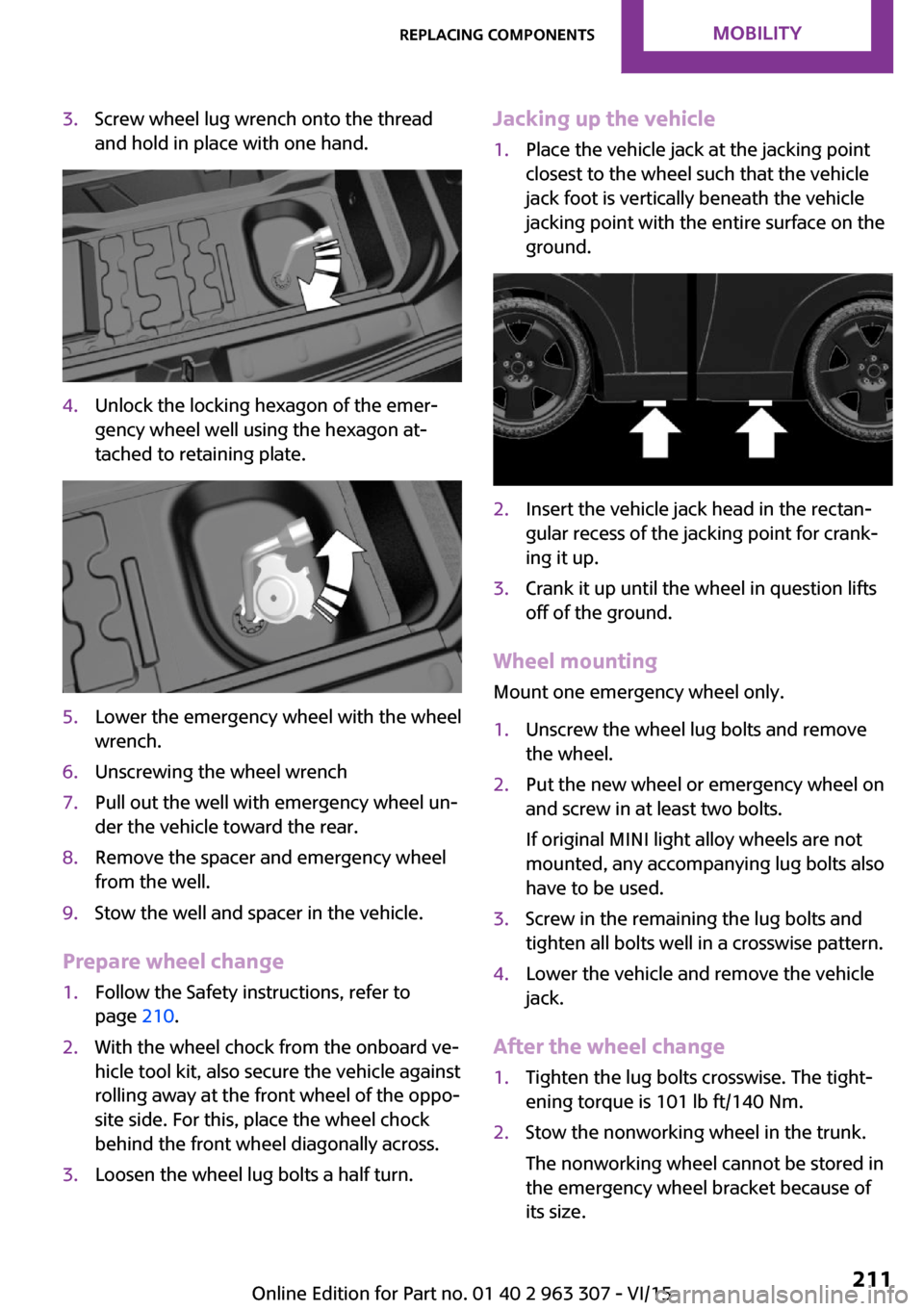
3.Screw wheel lug wrench onto the thread
and hold in place with one hand.4.Unlock the locking hexagon of the emer‐
gency wheel well using the hexagon at‐
tached to retaining plate.5.Lower the emergency wheel with the wheel
wrench.6.Unscrewing the wheel wrench7.Pull out the well with emergency wheel un‐
der the vehicle toward the rear.8.Remove the spacer and emergency wheel
from the well.9.Stow the well and spacer in the vehicle.
Prepare wheel change
1.Follow the Safety instructions, refer to
page 210.2.With the wheel chock from the onboard ve‐
hicle tool kit, also secure the vehicle against
rolling away at the front wheel of the oppo‐
site side. For this, place the wheel chock
behind the front wheel diagonally across.3.Loosen the wheel lug bolts a half turn.Jacking up the vehicle1.Place the vehicle jack at the jacking point
closest to the wheel such that the vehicle
jack foot is vertically beneath the vehicle
jacking point with the entire surface on the
ground.2.Insert the vehicle jack head in the rectan‐
gular recess of the jacking point for crank‐
ing it up.3.Crank it up until the wheel in question lifts
off of the ground.
Wheel mounting
Mount one emergency wheel only.
1.Unscrew the wheel lug bolts and remove
the wheel.2.Put the new wheel or emergency wheel on
and screw in at least two bolts.
If original MINI light alloy wheels are not
mounted, any accompanying lug bolts also
have to be used.3.Screw in the remaining the lug bolts and
tighten all bolts well in a crosswise pattern.4.Lower the vehicle and remove the vehicle
jack.
After the wheel change
1.Tighten the lug bolts crosswise. The tight‐
ening torque is 101 lb ft/140 Nm.2.Stow the nonworking wheel in the trunk.
The nonworking wheel cannot be stored in
the emergency wheel bracket because of
its size.Seite 211Replacing componentsMOBILITY211
Online Edition for Part no. 01 40 2 963 307 - VI/15
Page 213 of 251

Starting aid terminals
In the vehicle, only charge the battery via the
starting aid terminals, refer to page 215, in the
engine compartment with the engine off.
Power failure
After a temporary power loss, some equipment
needs to be newly initialized or individual set‐
tings updated, e. g.:▷Time: update.▷Date: update.▷Seat and mirror memory: store the posi‐
tions again.▷Glass sunroof: initialize the system, refer to
page 35.
Disposing of old batteries
Have old batteries disposed of by a
dealer’s service center or another quali‐
fied service center or repair shop or
take them to a collection point.
Maintain the battery in an upright position for
transport and storage. Secure the battery so
that it does not tip over during transport.
Fuses Information WARNING
Incorrect and repaired fuses can overload
electrical lines and components. There is risk of
fire. Never attempt to repair a blown fuse and
do not replace a nonworking fuse with a substi‐
tute of another color or amperage rating. ◀
Replacing fuse
The fuses are located in the passenger footwell
under the dashboard.1.To open, loosen screws, arrow 1.2.Fold down the fuse holder, arrow 2.
Information on the fuse types and locations
is found on a separate sheet.3.Replace the fuse in question.4.The installation is done in reverse order
from the removal.Seite 213Replacing componentsMOBILITY213
Online Edition for Part no. 01 40 2 963 307 - VI/15
Page 217 of 251

needs to be applied when braking and
steering.▷Larger steering wheel movements are re‐
quired.▷The towing vehicle must not be lighter than
the vehicle being towed; otherwise, it will
not be possible to control the vehicle's re‐
sponse.▷Do not exceed a towing speed of
30 mph/50 km/h.▷Do not exceed a towing distance of
30 miles/50 km.
Tow truck
Have your vehicle transported with a tow truck
with a so-called lift bar or on a flat bed.
CAUTION
When lifting the vehicle by the tow fitting
or body and chassis parts; damage can occur
on vehicle parts. There is risk of property dam‐
age. Lift vehicle using suitable means. ◀
Towing other vehicles
Information WARNING
If the approved gross vehicle weight of
the towing vehicle is lighter than the vehicle to
be towed, the tow fitting can tear off or it will
not be possible to control the vehicle's re‐
sponse. There is risk of an accident! Make sure
that the gross vehicle weight of the towing ve‐
hicle is heavier than the vehicle to be towed. ◀
CAUTION
If the tow bar or tow rope is attached in‐
correctly, damage to other vehicle parts can oc‐
cur. There is risk of property damage. Correctly
attach the tow bar or tow rope to the tow fit‐
ting. ◀▷Switch on the hazard warning system, de‐
pending on local regulations.▷If the electrical system has failed, clearly
identify the vehicle being towed by placing
a sign or a warning triangle in the rear win‐
dow.
Tow bar
The tow fittings used should be on the same
side on both vehicles.
Should it prove impossible to avoid mounting
the tow bar at an offset angle, please observe
the following:
▷Maneuvering capability is limited going
around corners.▷The tow bar will generate lateral forces if it
is secured with an offset.
Tow rope
When starting to tow the vehicle, make sure
that the tow rope is taut.
To avoid jerking and the associated stresses on
the vehicle components when towing, always
use nylon ropes or nylon straps.
CAUTION
If the tow bar or tow rope is attached in‐
correctly, damage to other vehicle parts can oc‐ cur. There is risk of property damage. Correctly
attach the tow bar or tow rope to the tow fit‐ ting. ◀
Seite 217Breakdown assistanceMOBILITY217
Online Edition for Part no. 01 40 2 963 307 - VI/15
Page 223 of 251

life. Use only a mild soapy solution for cleaning
the safety belts. ◀
Use only a mild soapy solution, with the safety
belts clipped into their buckles.
Do not allow the switchs to retract the safety
belts until they are dry.
Carpets and floor mats WARNING
Objects in the driver's floor area can limit
the pedal distance or block a depressed pedal.
There is risk of an accident. Stow objects in the
vehicle such that they are secured and cannot
enter into the driver's floor area. Use floor mats
that are suitable for the vehicle and can be
safely attached to the floor. Do not use loose
floor mats and do not layer several floor mats.
Make sure that there is sufficient clearance for
the pedals. Ensure that the floor mats are se‐
curely fastened again after they were removed,
e.g. for cleaning. ◀
Floor mats can be removed from the car's inte‐
rior for cleaning.
If the floor carpets are very dirty, clean with a
microfiber cloth and water or a textile cleaner.
To prevent matting of the carpet, rub back and
forth in the direction of travel only.
Sensor/camera lenses To clean sensors and camera lenses, use a cloth
moistened with a small amount of glass deter‐
gent.
Displays/Screens CAUTION
Chemical cleansers, moisture or fluids of
any kind can damage the surface of displays
and screens. There is risk of property damage.
Clean with a clean, antistatic microfiber cloth. ◀CAUTION
The surface of displays can be damaged
with improper cleaning. There is risk of prop‐
erty damage. Avoid pressure that is too high
and do not use any scratching materials. ◀
Clean with a clean, antistatic microfiber cloth.
Long-term
When the vehicle is shut down for longer than
three months, special measures must be taken.
Further information is available from a dealer’s
service center or another qualified service cen‐
ter or repair shop.Seite 223CareMOBILITY223
Online Edition for Part no. 01 40 2 963 307 - VI/15
Page 243 of 251

C
California Proposition 65 Warning 7
Camera-based cruise con‐ trol 101
Camera lenses, care 223
Can holder, see Cu‐ pholder 130
Car battery 212
Car care products 221
Care, displays 223
Care, vehicle 221
Cargo area 126
Cargo area, adapting size 131
Cargo area, enlarging 127
Cargo area lid 27
Cargo area, storage compart‐ ments 131
Cargo cover 126
Cargo, securing 140
Cargo straps, securing cargo 140
Car key, see Remote con‐ trol 22
Carpet, care 223
Car wash 220
Catalytic converter, see Hot exhaust system 137
CBS Condition Based Serv‐ ice 200
Center armrest 130
Center console 16
Central instrument cluster, LED ring 73
Central locking system 26
Changes, technical, refer to Own Safety 7
Changing parts 202
Changing the station 152
Changing wheels 210
Changing wheels/tires 186
Chassis number, see vehicle identification number 9
Check Control 63 Checking the oil level elec‐
tronically 195
Children, seating position 45
Children, transporting safely 45
Child restraint fixing sys‐ tem 45
Child restraint fixing system LATCH 47
Child restraint fixing systems, mounting 46
Child safety locks 48
Child seat, mounting 46
Child seats 45
Chrome parts, care 222
Chrono package, cockpit 74
Cigarette lighter 125
Cleaning, displays 223
Climate control 115, 117
Clock 67
Closing/opening via door lock 26
Closing/opening with remote control 24
Clothes hooks 131
Coasting 145
Coasting with engine decou‐ pled, coasting 145
Coasting with idling en‐ gine 145
Combination switch, see Turn signals 54
Combi switch, see wiper sys‐ tem 55
Comfort Access 28
Compartments in the doors 130
Compass 123
Compressor 188
Condensation on win‐ dows 119
Condensation under the vehi‐ cle 138
Condition Based Service CBS 200
Confirmation signal 30 Control systems, driving stabil‐
ity 97
Convenient opening 24
Coolant 198
Cooling function 116, 118
Cooling, maximum 118
Cooling system 198
Cornering lamp 78
Corrosion on brake discs 138
Cosmetic mirror 125
Courtesy lamps during unlock‐ ing 24
Courtesy lamps with the vehi‐ cle locked 25
Cruise control 106
Cruise control, active 101
Cruising range 67
Cupholder 130
Current fuel consumption 68
D
Damage, tires 186
Damping control, dynamic 99
Data, technical 226
Date 67
Date, radio 73
Date, setting on radio 73
Daytime running lights 78
Defrosting, refer to defrosting the windows 116
Defrosting, see Windows, de‐ frosting 119
Defrosting the windows 116
Dehumidifying, air 116, 118
Digital clock 67
Digital compass 123
Digital radio 153
Dimensions 226
Dimmable exterior mirrors 43
Dimmable interior rearview mirror 43
Direction indicator, see Turn signals 54
Display, electronic, instrument cluster 63 Seite 243Everything from A to ZREFERENCE243
Online Edition for Part no. 01 40 2 963 307 - VI/15
Page 244 of 251

Display, engine tempera‐ture 72
Display lighting, see Instru‐ ment lighting 79
Displays 62
Displays, cleaning 223
Disposal, coolant 199
Disposal, vehicle battery 213
Distance control, see PDC 108
Distance, setting units 72
Door lock, see Remote con‐ trol 22
Drive mode, GREEN mode 143
Drive-off assistant 100
Drive-off assistant, see DSC 97
Driving Dynamics Control 99
Driving instruction, GREEN mode 145
Driving instructions, break- in 136
Driving mode 99
Driving notes, general 136
Driving stability control sys‐ tems 97
Driving tips 136
DSC Dynamic Stability Con‐ trol 97
DTC Dynamic Traction Con‐ trol 98
Dynamic Damping Control 99
Dynamic Stability Control DSC 97
Dynamic Traction Control DTC 98
E Electronic displays, instrument cluster 63
Electronic oil measure‐ ment 195
Electronic Stability Program ESP, see DSC 97 Emergency detection, remote
control 23
Emergency release, fuel filler flap 174
Emergency start function, en‐ gine start 23
Emergency wheel, compact wheel, refer to Emergency
wheel 210
Energy Control 68
Engine, automatic Start/Stop function 51
Engine, automatic switch- off 51
Engine compartment 193
Engine compartment, working in 194
Engine coolant 198
Engine idling when driving, coasting 145
Engine oil 195
Engine oil, adding 196
Engine oil additives 197
Engine oil change 197
Engine oil filler neck 196
Engine oil types, alterna‐ tive 197
Engine oil types, suitable 197
Engine start during malfunc‐ tion 23
Engine start, jump-start‐ ing 214
Engine start, refer to Starting the engine 50
Engine stop 50
Engine temperature, dis‐ play 72
Entering a car wash 220
Equipment, interior 121
Error displays, see Check Con‐ trol 63
ESP Electronic Stability Pro‐ gram, see DSC 97
Exchanging wheels/tires 186
Exhaust system 137 Exterior mirror, automatic
dimming feature 43
Exterior mirrors 42
External start 214
External temperature dis‐ play 67
External temperature warn‐ ing 67
Eyes for securing cargo 140
F
Fader 150
Failure message, see Check Control 63
False alarm, refer to Uninten‐ tional alarm 31
Fan, refer to Air flow 116
Fan, see Air flow 119
Filler neck for engine oil 196
Fine wood, care 222
First-aid kit 214
Fitting for towing, see tow fit‐ ting 218
Flat tire, changing wheels 210
Flat Tire Monitor FTM 88
Flat tire, repairing 188
Flat tire, Tire Pressure Monitor TPM 84
Flat tire, warning lamp 85, 88
Flooding 137
Floor carpet, care 223
Floor mats, care 223
Fogged up windows 116
Folding back rear seat back‐ rests 127
Fold-out position, windshield wipers 57
Foot brake 137
Formats, setting 72
Front airbags 81
Front-end collision warning with City Braking func‐
tion 91
Front fog lights 79 Seite 244REFERENCEEverything from A to Z244
Online Edition for Part no. 01 40 2 963 307 - VI/15
Page 246 of 251

J
Jacking points for the vehicle jack 210
Joystick, Steptronic transmis‐ sion 58
Jump-starting 214
K
Key/remote control 22
Keyless Go, see Comfort Ac‐ cess 28
Key Memory, see Personal Profile 24
Kickdown, Steptronic trans‐ mission 58
Knee airbag 82
L
Label on recommended tires 186
Lamp replacement 203
Lamp replacement, front 204
Lamp replacement, rear 206
Lamp replacement, side 209
Language, setting 72
Lashing eyes, securing cargo 140
LATCH child restraint sys‐ tem 47
Launch Control 61
Leather, care 221
LED bug light 204
LED headlights 204
LED ring, central instrument cluster 73
LEDs, light-emitting di‐ odes 203
License Texts and Certifica‐ tions 235
Light 76
Light-alloy wheels, care 222
Light-emitting diodes, LEDs 203 Lighter 125
Lighting 76
Lights and bulbs 203
Light switch 76
Load 140
Loading 139
Lock, door 26
Locking/unlocking via door lock 26
Locking/unlocking with re‐ mote control 24
Locking, automatic 30
Locking, settings 29
Lock, power window 33
Locks, doors, and windows 48
Low beams 76
Low beams, automatic, see High-beam Assistant 78
Lower back support, mechani‐ cal 37
Luggage rack, refer to Roof- mounted luggage rack 140
Lumbar support, mechani‐ cal 37
M
Maintenance 200
Maintenance require‐ ments 200
Maintenance, service require‐ ments 68
Maintenance system, MINI 200
Make-up mirror 125
Malfunction displays, see Check Control 63
Manual air distribu‐ tion 116, 119
Manual air flow 116, 119
Manual mode, transmis‐ sion 59
Manual operation, door lock 26
Manual operation, exterior mirrors 42 Manual operation, fuel filler
flap 174
Manual operation, Park Dis‐ tance Control PDC 110
Manual transmission 58
Manufacturer of the MINI 7
Marking, run-flat tires 187
Master key, see Remote con‐ trol 22
Maximum cooling 118
Maximum speed, display 69
Maximum speed, winter tires 187
Medical kit 214
Menu in instrument cluster 70
Messages, see Check Con‐ trol 63
Microfilter 117, 120
MID - program, driving dy‐ namics 99
MINI maintenance sys‐ tem 200
Minimum tread, tires 185
Mirrors 42
Mobile communication devi‐ ces in the vehicle 137
Mobile phone 164
Mobility System 188
Mode, GREEN Mode 143
Modifications, technical, refer to Own Safety 7
Moisture in headlight 204
Mounting of child restraint systems 46
Multifunction steering wheel, buttons 14
N
Neck restraints, front, see Head restraints 40
Neck restraints, rear, see Head restraints 41
New wheels and tires 186
Nylon rope for tow-starting/ towing 217 Seite 246REFERENCEEverything from A to Z246
Online Edition for Part no. 01 40 2 963 307 - VI/15
Page 247 of 251

O
OBD Onboard Diagnos‐ tics 201
Octane rating, see Recom‐ mended fuel grade 176
Odometer 67
Oil 195
Oil, adding 196
Oil additives 197
Oil change 197
Oil change interval, service re‐ quirements 68
Oil filler neck 196
Oil types, alternative 197
Oil types, suitable 197
Old batteries, disposal 213
On-board computer 71
On-board computer, refer to On-board computer 71
Onboard Diagnostics OBD 201
Onboard vehicle tool kit 202
Opening/closing via door lock 26
Opening/closing with remote control 24
Optional equipment, standard equipment 6
Outside air, refer to Automatic recirculated-air control 119
Own safety 7
P
Paint, vehicle 221
Panoramic glass sunroof 33
Parallel parking assistant 111
Park Distance Control PDC 108
Parked vehicle, condensa‐ tion 138
Parking aid, see PDC 108
Parking assistant 111
Parking brake 53
Parking lights 76 Passenger side mirror, tilting
downward 42
PDC Park Distance Con‐ trol 108
Pedestrian warning with city braking function 94
Performance Control 98
Personal Profile 24
Phone 164
Pinch protection system, glass sunroof 34
Pinch protection system, win‐ dows 32
Plastic, care 222
PostCrash 96
Power failure 213
Power windows 31
Prescribed engine oil types 197
Pressure, tire air pressure 178
Pressure warning, tires 88
Profile, see Personal Pro‐ file 24
Protective function, glass sun‐ roof 34
Protective function, win‐ dows 32
R
Radiator fluid 198
Radio, AM/FM stations 151
Radio, Apple iPod/iPhone 157
Radio, AUX-IN port 156
Radio, control elements 151
Radio, external devices 156
Radio, FM/AM 151
Radio, muting 151
Radio-operated key, see Re‐ mote control 22
Radio, overview 151
Radio ready state 49
Radio, satellite radio 154
Radio, save stations 153
Radio, USB audio inter‐ face 157 Rain sensor 55
Rear fog lights 79
Rear lights 206
Rear luggage rack 141
Rearview mirror 42
Rear window de‐ froster 117, 119
Recirculated-air filter 120
Recirculated-air mode 116, 119
Recommended fuel grade 176
Recommended tire brands 186
Refueling 174
Remaining range 67
Remote control/key 22
Remote control, blocking 23
Remote control, malfunc‐ tion 25
Remote control, replacing the battery 22
Remote control, univer‐ sal 121
Replacement fuse 213
Replacing parts 202
Replacing the battery, remote control 22
Replacing wheels/tires 186
Reporting safety malfunc‐ tions 10
RES CNCL button, see camera- based cruise control 101
RES CNCL button, see Cruise control 106
Reserve warning, see Range 67
Resetting the tone set‐ tings 150
Reset, Tire Pressure Monitor TPM 85
Retaining straps, securing cargo 140
Retreaded tires 187
Roadside parking lights 77 Seite 247Everything from A to ZREFERENCE247
Online Edition for Part no. 01 40 2 963 307 - VI/15