ECU MINI Hardtop 4 Door 2016 Owner's Guide
[x] Cancel search | Manufacturer: MINI, Model Year: 2016, Model line: Hardtop 4 Door, Model: MINI Hardtop 4 Door 2016Pages: 251, PDF Size: 6.71 MB
Page 132 of 251
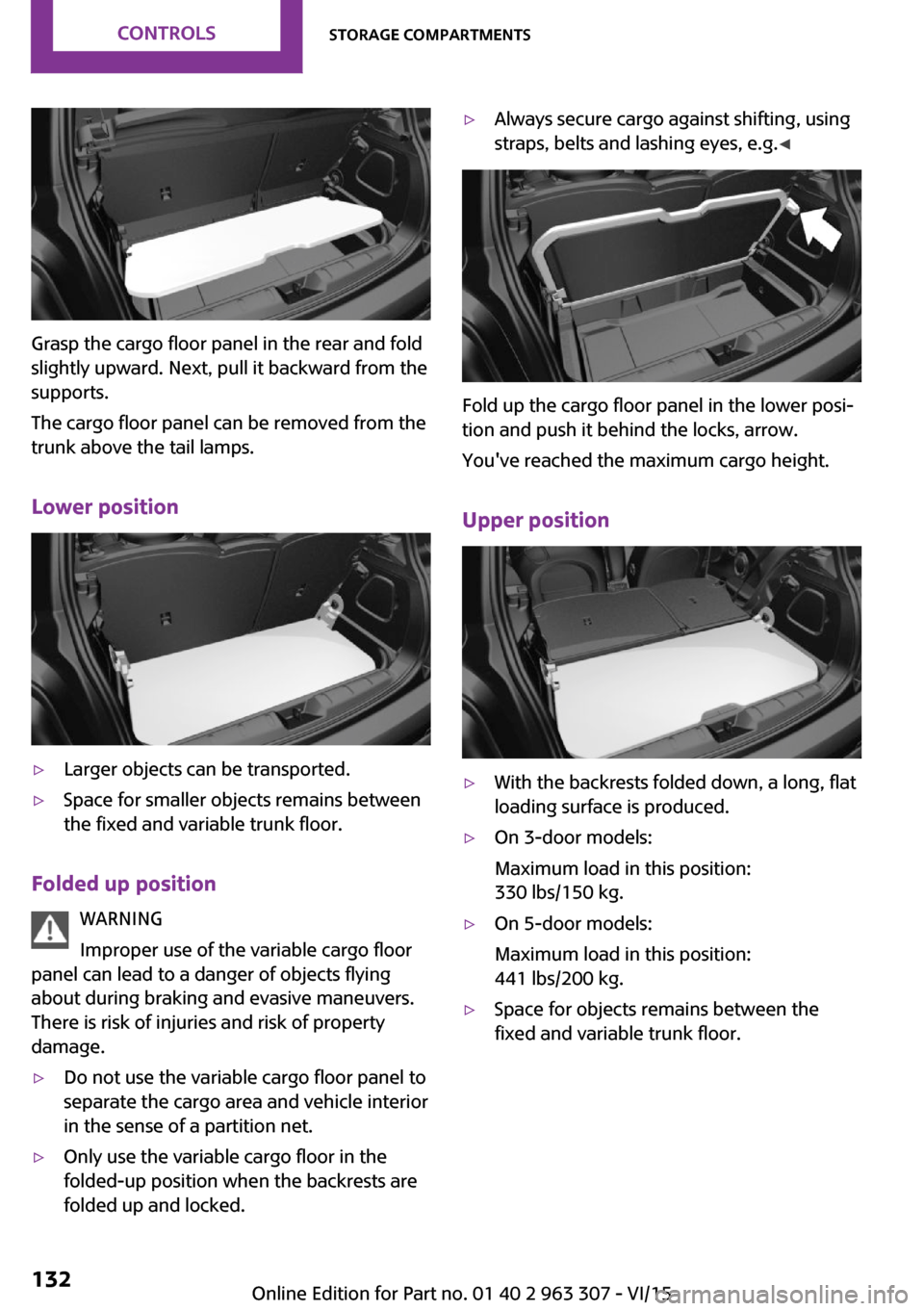
Grasp the cargo floor panel in the rear and fold
slightly upward. Next, pull it backward from the
supports.
The cargo floor panel can be removed from the
trunk above the tail lamps.
Lower position
▷Larger objects can be transported.▷Space for smaller objects remains between
the fixed and variable trunk floor.
Folded up position
WARNING
Improper use of the variable cargo floor
panel can lead to a danger of objects flying
about during braking and evasive maneuvers.
There is risk of injuries and risk of property
damage.
▷Do not use the variable cargo floor panel to
separate the cargo area and vehicle interior
in the sense of a partition net.▷Only use the variable cargo floor in the
folded-up position when the backrests are
folded up and locked.▷Always secure cargo against shifting, using
straps, belts and lashing eyes, e.g. ◀
Fold up the cargo floor panel in the lower posi‐
tion and push it behind the locks, arrow.
You've reached the maximum cargo height.
Upper position
▷With the backrests folded down, a long, flat
loading surface is produced.▷On 3-door models:
Maximum load in this position:
330 lbs/150 kg.▷On 5-door models:
Maximum load in this position:
441 lbs/200 kg.▷Space for objects remains between the
fixed and variable trunk floor.Seite 132CONTROLSStorage compartments132
Online Edition for Part no. 01 40 2 963 307 - VI/15
Page 137 of 251

If driving with the tailgate open cannot be
avoided:▷Close all windows and the glass sunroof.▷Greatly increase the air flow from the vents.▷Drive moderately.
Hot exhaust system
WARNING
During driving operation, high tempera‐
tures can occur underneath the body, e.g.
caused by the exhaust gas system. If combusti‐
ble materials, such as leaves or grass, come in
contact with hot parts of the exhaust gas sys‐
tem, these materials can ignite. There is risk of
injuries or risk of property damage.
Do not remove the heat shields installed and
never apply undercoating to them. Make sure
that no combustible materials can come in con‐
tact with hot vehicle parts in driving operation,
idle or during parking. Do not touch the hot ex‐
haust system. ◀
Mobile communication devices in the vehicle
WARNING
Vehicle electronics and mobile phones
can influence one another. There is radiation
due to the send operations of mobile phones.
There is risk of injuries or risk of property dam‐
age. If possible, in the car's interior use only
mobile phones with direct connections to an
exterior antenna in order to exclude mutual
disturbance and deflect the radiation from the
car's interior. ◀
Hydroplaning On wet or slushy roads, a wedge of water can
form between the tires and road surface.
This phenomenon is referred to as hydroplan‐
ing. It is characterized by a partial or complete
loss of contact between the tires and the road
surface, ultimately undermining your ability to
steer and brake the vehicle.
Driving through water
CAUTION
When driving too quickly through too
deep water, water can enter into the engine
compartment, the electrical system or the
transmission. There is risk of property damage.
When driving through water, do not exceed the
maximum indicated water level and the maxi‐
mum speed for driving through water. ◀
Drive through calm water only if it is not deeper
than 9.8 inches/25 cm and at this height, no
faster than walking speed, up to 3 mph/5 km/h.
Braking safely
Your vehicle is equipped with ABS as a standard
feature.
Applying the brakes fully is the most effective
way of braking in situations needed.
Steering is still responsive. You can still avoid
any obstacles with a minimum of steering ef‐
fort.
Pulsation of the brake pedal and sounds from
the hydraulic circuits indicate that ABS is in its
active mode.
Objects in the movement area around
pedals and floor area
WARNING
Objects in the driver's floor area can limit
the pedal distance or block a depressed pedal.
There is risk of an accident. Stow objects in the
vehicle such that they are secured and cannot
enter into the driver's floor area. Use floor mats
that are suitable for the vehicle and can be
safely attached to the floor. Do not use loose
floor mats and do not layer several floor mats.
Make sure that there is sufficient clearance for
the pedals. Ensure that the floor mats are se‐
curely fastened again after they were removed,
e.g. for cleaning. ◀Seite 137Things to remember when drivingDRIVING TIPS137
Online Edition for Part no. 01 40 2 963 307 - VI/15
Page 139 of 251

LoadingVehicle features and op‐tions
This chapter describes all standard, country-
specific and optional features offered with the
series. It also describes features that are not
necessarily available in your car, e. g., due to
the selected options or country versions. This
also applies to safety-related functions and sys‐
tems. The respectively applicable country provi‐
sions must be observed when using the respec‐
tive features and systems.
Information WARNING
High gross weight can overheat the tires,
damage them internally, and cause a sudden
drop in tire inflation pressure. There is risk of an
accident. Pay attention to the permitted load
capacity of the tires and never exceed the per‐
mitted gross weight. ◀
CAUTION
Fluids in the cargo area can cause dam‐
age. There is risk of property damage. Make
sure that no fluids leak in the cargo area. ◀
WARNING
Loose objects in the car's interior can be
thrown into the car's interior while driving, e.g.
in the event of an accident or during braking
and evasive maneuvers. There is risk of injuries.
Secure loose objects in the car's interior. ◀Determining the load
limit1.Locate the following statement on your ve‐
hicle’s placard:▷The combined weight of occupants and
cargo should never exceed XXX kg or
YYY lbs. Otherwise, damage to the ve‐
hicle and unstable driving situations
may result.2.Determine the combined weight of the
driver and passengers that will be riding in
your vehicle.3.Subtract the combined weight of the driver
and passengers from XXX kilograms or YYY
pounds.4.The resulting figure equals the available
amount of cargo and luggage load ca‐
pacity.
For example, if the YYY amount equals
1,000 lbs and there will be four 150 lbs pas‐
sengers in your vehicle, the amount of
available cargo and luggage load capacity
is 400 lbs: 1,000 lbs minus 600 lbs =
400 lbs.5.Determine the combined weight of luggage
and cargo being loaded on the vehicle.
That weight may not safely exceed the
available cargo and luggage load capacity
calculated in Step 4.Seite 139LoadingDRIVING TIPS139
Online Edition for Part no. 01 40 2 963 307 - VI/15
Page 140 of 251
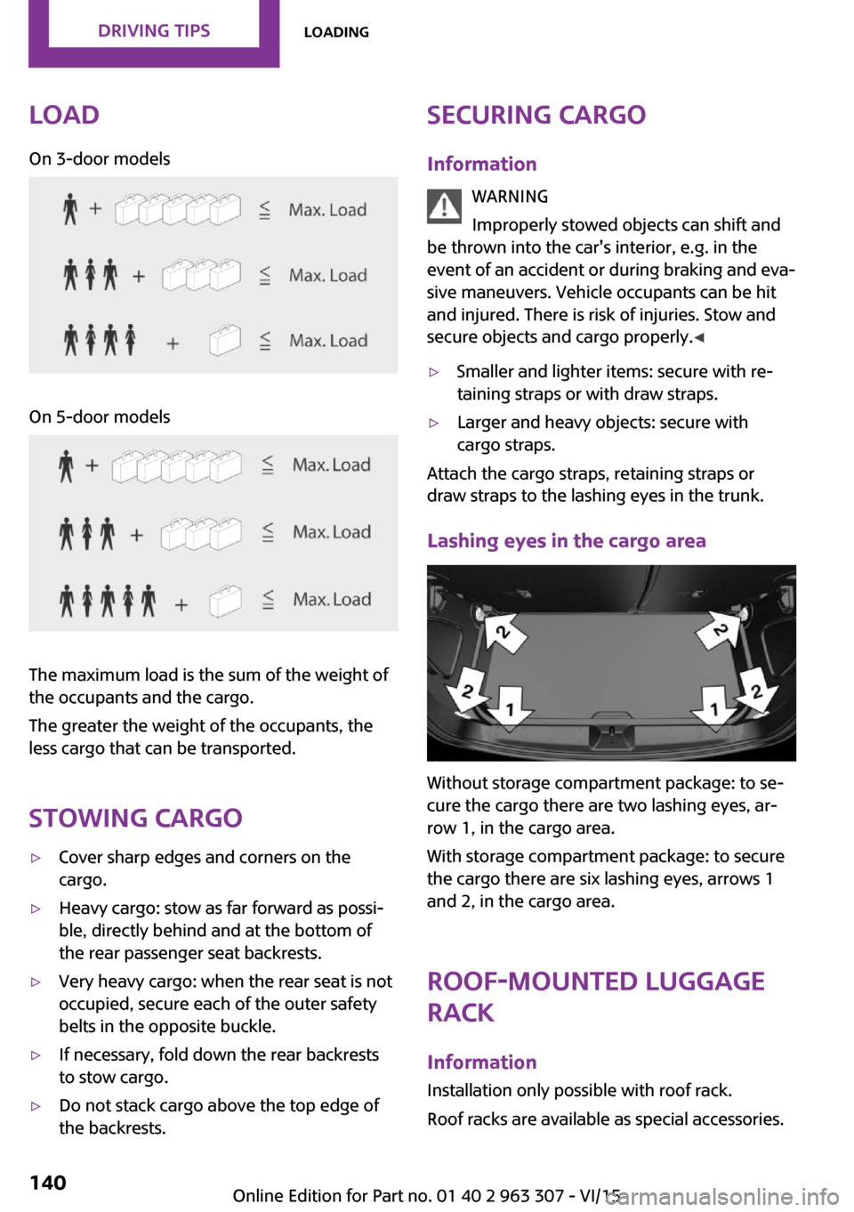
LoadOn 3-door modelsOn 5-door models
The maximum load is the sum of the weight of
the occupants and the cargo.
The greater the weight of the occupants, the
less cargo that can be transported.
Stowing cargo
▷Cover sharp edges and corners on the
cargo.▷Heavy cargo: stow as far forward as possi‐
ble, directly behind and at the bottom of
the rear passenger seat backrests.▷Very heavy cargo: when the rear seat is not
occupied, secure each of the outer safety
belts in the opposite buckle.▷If necessary, fold down the rear backrests
to stow cargo.▷Do not stack cargo above the top edge of
the backrests.Securing cargo
Information WARNING
Improperly stowed objects can shift and
be thrown into the car's interior, e.g. in the
event of an accident or during braking and eva‐
sive maneuvers. Vehicle occupants can be hit
and injured. There is risk of injuries. Stow and
secure objects and cargo properly. ◀▷Smaller and lighter items: secure with re‐
taining straps or with draw straps.▷Larger and heavy objects: secure with
cargo straps.
Attach the cargo straps, retaining straps or
draw straps to the lashing eyes in the trunk.
Lashing eyes in the cargo area
Without storage compartment package: to se‐
cure the cargo there are two lashing eyes, ar‐
row 1, in the cargo area.
With storage compartment package: to secure
the cargo there are six lashing eyes, arrows 1
and 2, in the cargo area.
Roof-mounted luggage
rack
Information Installation only possible with roof rack.
Roof racks are available as special accessories.
Seite 140DRIVING TIPSLoading140
Online Edition for Part no. 01 40 2 963 307 - VI/15
Page 141 of 251
Securing
Follow the installation instructions of the roof
rack.
Loading Because roof racks raise the vehicle's center of
gravity when loaded, they have a major effect
on vehicle handling and steering response.
Therefore, note the following when loading and
driving:▷Do not exceed the approved roof/axle
loads and the approved gross vehicle
weight.▷Be sure that adequate clearance is main‐
tained for tilting and opening the glass sun‐
roof.▷Distribute the roof load uniformly.▷The roof load should not extend past the
loading area.▷Always place the heaviest pieces on the
bottom.▷Secure the roof luggage firmly, e.g., tie with
ratchet straps.▷Do not let objects project into the opening
path of the tailgate.▷Drive cautiously and avoid sudden acceler‐
ation and braking maneuvers. Take corners
gently.
Rear luggage rack
General information Installation only possible with rear luggage rack
preparation.
Rear racks are available as special accessories.
Information Follow the installation instructions of the rear
luggage rack.
Drive cautiously and avoid sudden acceleration
and braking maneuvers. Take corners gently.
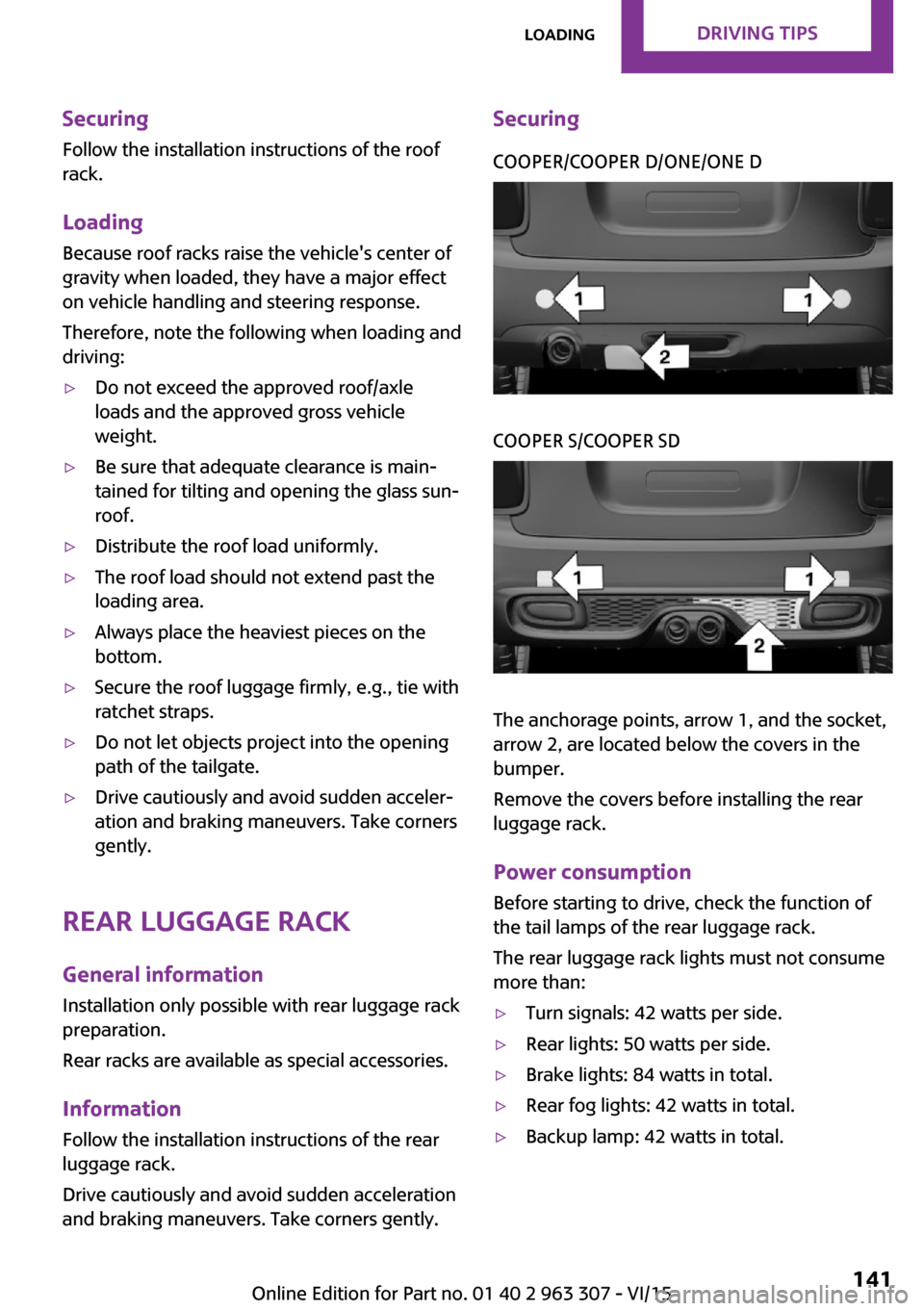
SecuringCOOPER/COOPER D/ONE/ONE DCOOPER S/COOPER SD
The anchorage points, arrow 1, and the socket,
arrow 2, are located below the covers in the
bumper.
Remove the covers before installing the rear
luggage rack.
Power consumption
Before starting to drive, check the function of
the tail lamps of the rear luggage rack.
The rear luggage rack lights must not consume
more than:
▷Turn signals: 42 watts per side.▷Rear lights: 50 watts per side.▷Brake lights: 84 watts in total.▷Rear fog lights: 42 watts in total.▷Backup lamp: 42 watts in total.Seite 141LoadingDRIVING TIPS141
Online Edition for Part no. 01 40 2 963 307 - VI/15
Page 164 of 251
Bluetooth hands-free systemVehicle features and op‐
tions
This chapter describes all standard, country-
specific and optional features offered with the
series. It also describes features that are not
necessarily available in your car, e. g., due to
the selected options or country versions. This
also applies to safety-related functions and sys‐
tems. The respectively applicable country provi‐
sions must be observed when using the respec‐
tive features and systems.
The concept Mobile phones can be connected to the vehicle
via Bluetooth. After the mobile phones are
paired once, they are recognized automatically
when the ignition is switched on. As soon as
they are inside the vehicle they can be oper‐
ated via the radio and via the buttons on the
steering wheel.
Information WARNING
Operating the integrated information sys‐
tem and communication devices while driving
can distract from traffic. It is possible to lose
control of the vehicle. There is risk of an acci‐
dent. Only use the systems or devices when the
traffic situation allows. If necessary stop and
use the systems and devices while the vehicle is
stationary. ◀
Certain functions may need to be enabled by
the mobile phone provider or service provider.
At high temperatures, the charge functions of
the mobile phone can be limited under certain
circumstances, and some functions are no lon‐
ger executed.Do not operate a mobile phone that is con‐
nected to the vehicle on the mobile phone key‐
pad, as this may lead to a malfunction.
When the mobile phone is used via the vehicle,
refer to the operating manual of the mobile
phone.
Compatible mobile
phones
Accurate information about which mobile
phones are supported with a Bluetooth inter‐
face is available at www.mini.com/connectivity.
These compatible mobile phones, with a cer‐
tain software version, support the vehicle func‐
tions described below.
Malfunctions may occur with other mobile
phones or software versions.
Displaying the vehicle identification
number and software part number
The vehicle identification number and software
part number are needed to determine which
mobile phones are supported by the mobile
phone installation package. The software ver‐
sion of the mobile phone may also be required.1. "Telephone"2. Press button.3."Bluetooth® info"4."System information"
Pairing/unpairing the
mobile phone
Requirements
▷The mobile phone is compatible.Seite 164COMMUNICATIONBluetooth hands-free system164
Online Edition for Part no. 01 40 2 963 307 - VI/15
Page 165 of 251
▷The mobile phone is ready for operation.▷The ignition is switched on.▷Bluetooth connection on the vehicle and on
the mobile phone activated.▷Bluetooth presets may need to be made on
the mobile phone, e.g., for a connection
without confirmation or visibility, refer to
the mobile phone operating instructions.▷Set Bluetooth passkey for one-time use in
the logon procedure.▷Vehicle is stationary.
Bluetooth activation/deactivation
1. "Telephone"2. Press button.3."Bluetooth®"
Pairing and connecting
WARNING
Operating the integrated information sys‐
tem and communication devices while driving
can distract from traffic. It is possible to lose
control of the vehicle. There is risk of an acci‐
dent. Only use the systems or devices when the
traffic situation allows. If necessary stop and
use the systems and devices while the vehicle is
stationary. ◀
1. "Telephone"2.A mobile phone has not yet been paired:
"OK"
A mobile phone has been paired:
"Bluetooth®"3.A mobile phone has not yet been paired:
the Bluetooth name of the vehicle is shown
on the display.
A mobile phone has not yet been paired:
"Add new phone". The Bluetooth name of
the vehicle is shown on the display.4.To perform additional steps on the mobile
phone, refer to the mobile phone operating
instructions.The Bluetooth name of the vehicle appears
on the mobile phone display. Select this.5.Enter the same passkey on the mobile
phone and on the display
or
Compare the control number on the display
with the control number in the display of
the mobile phone and confirm.
Four mobile phones can be logged in on the
vehicle, and one mobile phone can be con‐
nected to the vehicle.
Following the initial pairing Mobile phone is connected to the vehicle after
a brief time.
The phone book entries stored on the SIM card
or in the mobile phone are transferred to the
vehicle.
Specific settings may be necessary in some mo‐
bile phones, e.g., authorization or a secure con‐
nection; refer to the mobile phone operating
instructions.
Connecting a particular mobile phone
1. "Telephone"2."Bluetooth®"3.Select the mobile phone that is to be con‐
nected.
Unpairing the mobile phone
1. "Telephone"2."Bluetooth®"3.Highlight any mobile phone that is to be re‐
moved.4. Press button.5."Remove device" or "Remove all devices"
What to do if...
Information on compatible mobile phones, re‐
fer to page 164.
Seite 165Bluetooth hands-free systemCOMMUNICATION165
Online Edition for Part no. 01 40 2 963 307 - VI/15
Page 188 of 251

Continued driving with a damaged tire, refer to
page 86.
Changing run-flat tires
For your own safety, only use run-flat tires. No
spare tire is available in the case of a flat tire. A
dealer’s service center or another qualified
service center or repair shop will be glad to an‐
swer additional questions at any time.
Repairing a flat tireSafety measures▷Park the vehicle as far away as possible
from passing traffic and on solid ground.▷Switch on the hazard warning system.▷Secure the vehicle against rolling away by
setting the parking brake.▷Turn the steering wheel until the front
wheels are in the straight-ahead position
and engage the steering wheel lock.▷Have all vehicle occupants get out of the
vehicle and ensure that they remain out‐
side the immediate area in a safe place,
such as behind a guardrail.▷If necessary, set up a warning triangle at an
appropriate distance.
Mobility System
The concept
With the Mobility System, minor tire damage
can be sealed quickly to enable continued
travel. To accomplish this, sealant is pumped
into the tires, which seals the damage from the
inside.
The compressor can be used to check the tire
inflation pressure.
Information▷Follow the instructions on using the Mobi‐
lity System found on the compressor and
sealant container.▷Use of the Mobility System may be ineffec‐
tive if the tire puncture measures approx.
1/8 in/4 mm or more.▷Contact a dealer’s service center or another
qualified service center or repair shop if the
tire cannot be made drivable.▷If possible, do not remove foreign bodies
that have penetrated the tire.▷Pull the speed limit sticker off the sealant
container and apply it to the steering
wheel.▷The use of a sealant can damage the TPM
wheel electronics. In this case, have the
electronics checked at the next opportunity
and have them replaced if needed.
DANGER
If the exhaust pipe is blocked or ventila‐
tion is insufficient, harmful exhaust gases can
enter into the vehicle. The exhaust gases con‐
tain carbon monoxide, an odorless and color‐
less but highly toxic gas. In enclosed areas, ex‐
haust gases can also accumulate outside of the
vehicle. There is danger to life. Keep the ex‐
haust pipe free and ensure sufficient ventila‐
tion. ◀
Storage
The Mobility System is located under the cargo
floor panel.
Seite 188MOBILITYWheels and tires188
Online Edition for Part no. 01 40 2 963 307 - VI/15
Page 194 of 251

Hood
Information WARNING
Improperly executed work in the engine
compartment can damage components and
lead to a safety risk. There is risk of accidents or
risk of property damage. ◀
WARNING
The engine compartment accommodates
moving components. Certain components can
move in the engine compartment with the ve‐
hicle switched off, e.g. the cooler fan. There is
risk of injuries. Do not reach into the area of
moving parts. Keep articles of clothing and hair
away from moving parts. ◀
CAUTION
Folded-away wipers can be jammed
when the hood is opened. There is risk of prop‐
erty damage. Make sure that the wipers with
the wiper blades mounted are folded down onto the windshield before opening the
hood. ◀
WARNING
There are protruding parts, e.g. lock
hook, on the inside of the hood. There is risk of
injuries. If the hood is open, pay attention to
protruding parts and keep these areas clear. ◀
WARNING
An incorrectly locked hood can open
while driving and restrict visibility. There is risk
of an accident. Stop immediately and correctly
close the hood. ◀
WARNING
Body parts can be jammed on opening
and closing the hood. There is risk of injuries.
Make sure that the area of movement of the
hood is clear during opening and closing. ◀Opening the hood1.Pull lever, arrow 1.
Hood is unlocked.2.After the lever is released, pull the lever
again, arrow 2.
Hood can be opened.
Indicator/warning lights
When the hood is opened, a Check Control
message is displayed.
Closing the hood
Let the hood fall from approx. 16 in/40 cm, ar‐
row.
The hood must audibly engage on both sides.
Seite 194MOBILITYEngine compartment194
Online Edition for Part no. 01 40 2 963 307 - VI/15
Page 202 of 251
Replacing componentsVehicle features and op‐
tions
This chapter describes all standard, country-
specific and optional features offered with the
series. It also describes features that are not
necessarily available in your car, e. g., due to
the selected options or country versions. This
also applies to safety-related functions and sys‐
tems. The respectively applicable country provi‐
sions must be observed when using the respec‐
tive features and systems.
Onboard vehicle tool kit
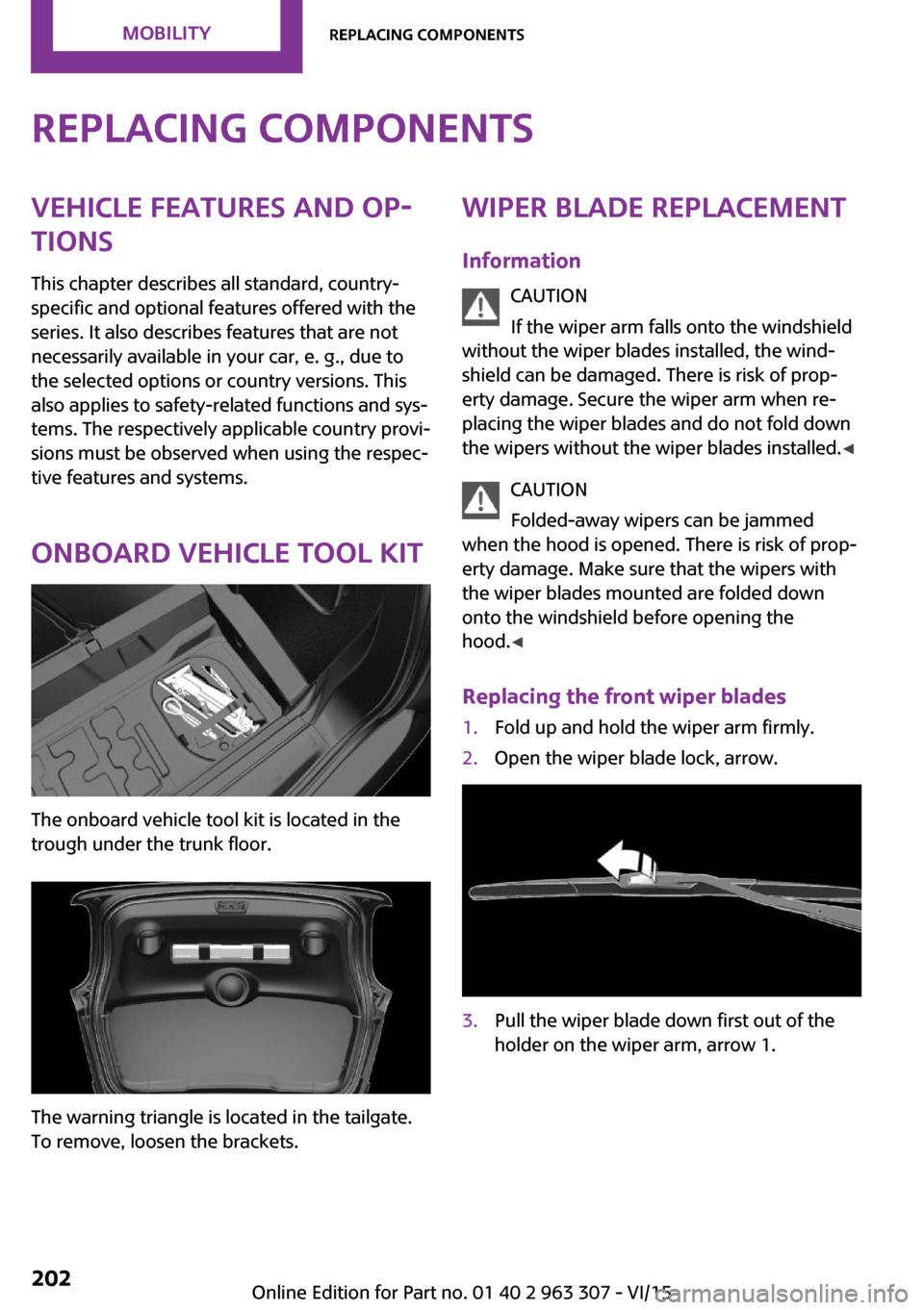
The onboard vehicle tool kit is located in the
trough under the trunk floor.
The warning triangle is located in the tailgate.
To remove, loosen the brackets.
Wiper blade replacement
Information CAUTION
If the wiper arm falls onto the windshield
without the wiper blades installed, the wind‐
shield can be damaged. There is risk of prop‐
erty damage. Secure the wiper arm when re‐
placing the wiper blades and do not fold down
the wipers without the wiper blades installed. ◀
CAUTION
Folded-away wipers can be jammed
when the hood is opened. There is risk of prop‐
erty damage. Make sure that the wipers with
the wiper blades mounted are folded down
onto the windshield before opening the
hood. ◀
Replacing the front wiper blades1.Fold up and hold the wiper arm firmly.2.Open the wiper blade lock, arrow.3.Pull the wiper blade down first out of the
holder on the wiper arm, arrow 1.Seite 202MOBILITYReplacing components202
Online Edition for Part no. 01 40 2 963 307 - VI/15