MINI Paceman 2014 Owner's Manual (Mini Connected)
Manufacturer: MINI, Model Year: 2014, Model line: Paceman, Model: MINI Paceman 2014Pages: 282, PDF Size: 6.76 MB
Page 111 of 282

Before beginning with the mounting of a child
restraint fixing system, note the instructions,
refer to page 53.1.Hold the top of the backrest, for example
the head restraint, and pull on the loop, ar‐
row.2.Engage the backrest in the desired position
or fold it down.
Folding the backrests back up
Locking the backrest
When folding back, ensure that the locks
engage properly; otherwise, cargo could be
catapulted forward into the passenger com‐
partment during braking maneuvers and
swerving, endangering the occupants. ◀
No child restraint fixing systems
Do not mount child restraint fixing sys‐
tems in the rear when the rear seat backrests
are adjusted to a more vertical position; other‐
wise, the protection provided by these systems
may be reduced. ◀
When the backrests are folded back up, they
engage in the transport position.
To set the desired backrest inclination or com‐
fort position, hold the backrest, pull the loop
forward, and adjust the backrest.
MINI Paceman: rear seat backrests
Danger of pinching
Before folding down the rear seat back‐
rests, ensure that path of movement of the
backrests is clear; otherwise, injuries or damage
may result. ◀1.Pull on the respective loop, arrow.
The backrest is unlocked.2.Fold the backrest forward.
Folding the backrests back up Hold the top of the backrest, for example the
head restraint, and fold it back.
Locking the backrest
When folding back, ensure that the locks
engage properly; otherwise, cargo could be
catapulted forward into the passenger com‐
partment during braking maneuvers and
swerving, endangering the occupants. ◀
Flat loading floor Maximum load
Do not exceed the maximum load of
330 lbs, 150 kg, on the loading floor; otherwise,
damage may result. ◀
Access to storage area A storage area for items like the partition net is
found under the loading floor.
1.Reach into the recess, arrow 1, on the rear
edge of the loading floor.Seite 111Interior equipmentControls111
Online Edition for Part no. 01 40 2 911 544 - VI/13
Page 112 of 282

2.Lift the loading floor at the rear, arrow 1,
and fold it forward, arrow 2.
MINI Countryman:
MINI Paceman:
Before closing the tailgate, lower the loading
floor back onto the cargo area floor.
Removing
The loading floor can be removed if necessary.
1.Fold up the loading floor.2.Pull it back slightly and out of the holders.3.Then remove it upward.
The folded loading floor can be stored in the
cargo area.
MINI Countryman: partition net Firmly attach the partition net
Make sure that the partition net is firmly
attached; otherwise, injuries may result. ◀
Before installing1.Remove the pouch with the partition net
from the storage compartment under the
loading floor in the cargo area.2.Take the partition net out of the pouch, un‐
roll it, and unfold it.
After use, fold and roll up the partition net
in the same manner and place it in the
pouch so that it can be stowed back under
the cargo floor panel. Ensure that hooks
and tensioning buckles do not rest on the
rod elements.3.Unfold the partition net to the point where
the rod elements engage.
Installation behind the front seats
1.Take out the cargo cover if necessary.2.Fold down the rear seat backrests, refer to
Enlarging the cargo area.3.Insert the retaining pins of the partition net
all the way into the front holders in the
headliner, arrow 1, and push forward.4.Attach the hooks, arrow 2, at the bottom of
the retaining straps on both sides to the
eyelets on the vehicle floor.5.Lash the partition net tightly. To do this,
tighten the retaining straps using the ten‐
sioning buckles.
Removing
To remove and stow the partition net, proceed
in reverse order.
Seite 112ControlsInterior equipment112
Online Edition for Part no. 01 40 2 911 544 - VI/13
Page 113 of 282

To fold up, press the release button, arrow.
MINI Countryman: multi-function hook
Hooks designed for hanging shopping bags and
totes, for example, are located on the left and
right sides of the cargo cover support, arrow.
Do not hang heavy items from the hooks
Only hang light bags or suitable objects
from the holders. Otherwise, there is a danger
of objects flying about during braking and eva‐
sive maneuvers.
Only transport heavy luggage in the trunk if it
has been appropriately secured. ◀
Seite 113Interior equipmentControls113
Online Edition for Part no. 01 40 2 911 544 - VI/13
Page 114 of 282

Storage compartmentsVehicle equipment
This chapter describes all series equipment as
well as country-specific and special equipment
offered for this model series.Therefore, it also
describes equipment that may not be found in
your vehicle, for instance due to the selected
special equipment or the country version. This
also applies to safety-related functions and sys‐
tems.
Notes No loose objects in the passenger com‐partment
Do not stow any objects in the passenger com‐
partment without securing them; otherwise,
they may present a danger to occupants for in‐
stance during braking and avoidance maneu‐
vers. ◀
No non-slip mats on the dashboard
Do not use non-slip materials, such as
non-slip mats, on the dashboard, or it could be
damaged by the substances in the materials. ◀
Storage compartments
Interior▷Glove compartment, refer to page 114.▷Center armrest, refer to page 115.▷Center rail, refer to page 116.▷Compartments in the center console.▷Compartments in the doors.▷Pockets on the back of the front seat back‐
rests.▷Cupholder, refer to page 108.▷Clothes hooks, refer to page 117.Cargo area▷Lashing eyes, refer to page 127.▷Storage compartment under the flat load‐
ing floor, refer to page 111.▷Multi-function hook on the cargo cover
support, refer to page 113.
Glove compartment
Opening
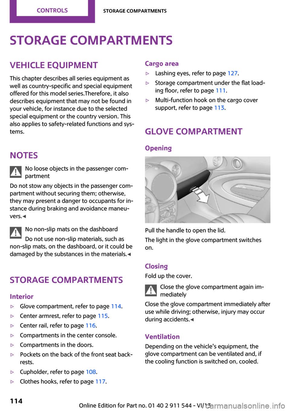
Pull the handle to open the lid.
The light in the glove compartment switches
on.
Closing Fold up the cover.
Close the glove compartment again im‐
mediately
Close the glove compartment immediately after
use while driving; otherwise, injury may occur
during accidents. ◀
Ventilation
Depending on the vehicle's equipment, the
glove compartment can be ventilated and, if
the cooling function is switched on, cooled.
Seite 114ControlsStorage compartments114
Online Edition for Part no. 01 40 2 911 544 - VI/13
Page 115 of 282

Opening
Turn the switch in the direction of the arrow.ClosingMove the switch to the vertical position by
turning it in the opposite direction of the arrow.
Depending on the temperature setting of the
air conditioning or automatic climate control,
high temperatures may occur in the glove com‐
partment.
USB interface for data transfer Updating the navigation data, refer to
page 134, from the USB medium via the USB
interface in the glove compartment.
Observe the following when connecting:
▷Do not use force when plugging the con‐
nector into the USB interface.▷Do not connect devices such as fans or
lamps to the USB interface.▷Do not connect USB hard drives.▷Do not use the USB interface to recharge
external devices.
Center armrest
The center armrest between the front seats
contains a storage compartment or a cover for
the snap-in adapter, refer to page 200, de‐
pending on the equipment.
The center armrest between the rear seats con‐
tains a storage compartment.
Do not position tall accessory parts directly on
the center rail of the center armrest; otherwise,
they may be damaged when the center arm‐
rest is opened or closed.
Center armrest front
Opening
Press the button, arrow, and pull up the lid.
MINI Paceman: center armrest, rear
Removing
The rear center armrest can be removed to en‐
large the loading area.
1.Turn the handwheel counterclockwise all
the way to open it, arrow 1.2.Push the center armrest back slightly in the
base plate, arrow 2.3.Lift the center armrest at the front and
pivot it out.Seite 115Storage compartmentsControls115
Online Edition for Part no. 01 40 2 911 544 - VI/13
Page 116 of 282

Installing1.Insert the center armrest into the rear re‐
cess of the base plate, arrow 1.2.Push it back and pivot it down at the front,
arrow 2.3.Push the center armrest forward in the base
plate.4.Tighten the handwheel by turning it clock‐
wise.
Ensure that the center armrest engages prop‐
erly when installed; otherwise, it could become
damaged during braking maneuvers, for exam‐
ple.
Center rail Various accessory parts can be mounted on the
center rail and moved to different positions.
Do not use accessory parts in the area of the
handbrake; otherwise, they may become dam‐
aged when the handbrake lever is activated.
Smartphone cradle The upper part of the smartphone cradle can
be rotated by 360°.
When installing it at the front of the rail, ensure
that it is surrounded by adequate clearance,
such as toward the seat; otherwise, damage
may result when it is rotated.
1.Pull up the lever 1 to unlock the holders.2.Insert the smartphone cradle into the cen‐
ter rail with the holders 2 first.3.To fix, push the lever 1 downward. Ensure
that the lever is properly engaged.
When connecting a smartphone to the USB au‐
dio interface, refer to page 170, pass the con‐
nection cable under the smartphone cradle.
In addition, the connection cable can be at‐
tached inside the rail.
1.Twist the rail segment, arrow 1, to remove
it.2.Insert the connection cable centrally into
the recess, arrow 2.3.Fix the rail segment in the rail.
Base plate
Various accessory parts such as cupholders,
eyeglass holders, and mobile phone cradles can
be mounted on the base plate.
Inserting the base plate
The lever 3 can be engaged in three positions.
Seite 116ControlsStorage compartments116
Online Edition for Part no. 01 40 2 911 544 - VI/13
Page 117 of 282

0Setting1Adjusting the position on the rail2Inserting the base plate
To insert, move the lever to position 2.
Adjusting the position and fixing
1.Push lever 3 into position 1.2.Adjust the position of the base plate.3.Push lever 3 downward into position 0.
Do not apply excessive pressure to the
lever.
The base plate is fixed.
Fix the base plate
Fix the base plate before driving away;
otherwise, injuries may result during an acci‐
dent. ◀
An example: eyeglass holder
Attach the eyeglass holder and adjust the posi‐
tion.
Mounting the eyeglass holder
1.If necessary, fix the base plate, refer to Ad‐
justing the position and fixing.2.Pull up lever 6 to unlock the holders.3.First engage the eyeglass holder in the
front holders 4 and then in the rear hold‐
ers 5.
Ensure that lever 6 is across from holder 4.
Clothes hooks Clothes hooks are located on the grab handles
in the rear.
Do not obstruct view
When suspending clothing from the
hooks, ensure that it will not obstruct the driv‐
er's vision. ◀
No heavy objects
Do not hang heavy objects from the
hooks; otherwise, they may present a danger
to passengers during braking and evasive ma‐
neuvers. ◀
Seite 117Storage compartmentsControls117
Online Edition for Part no. 01 40 2 911 544 - VI/13
Page 118 of 282

Connection for an exter‐
nal audio device
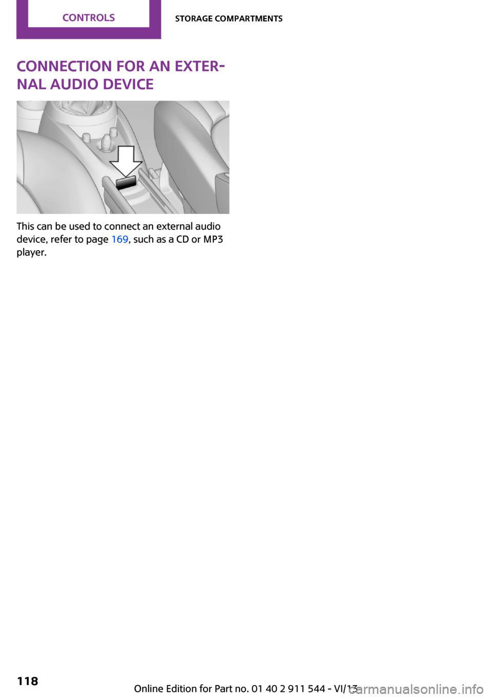
This can be used to connect an external audio
device, refer to page 169, such as a CD or MP3
player.
Seite 118ControlsStorage compartments118
Online Edition for Part no. 01 40 2 911 544 - VI/13
Page 119 of 282

Seite 119Storage compartmentsControls119
Online Edition for Part no. 01 40 2 911 544 - VI/13
Page 120 of 282

DRIVE ME.
Online Edition for Part no. 01 40 2 911 544 - VI/13