checking oil MITSUBISHI 3000GT 1991 Owner's Manual
[x] Cancel search | Manufacturer: MITSUBISHI, Model Year: 1991, Model line: 3000GT, Model: MITSUBISHI 3000GT 1991Pages: 1146, PDF Size: 76.68 MB
Page 871 of 1146
4-WHEEL STEERING SYSTEM (4WS) - Rear Oil Pump37B-11
REAR OIL PUMP
REMOVAL AND INSTALLATION/
l Draining of Power Steering Fluid
(Refer to GROUP 37A- Service Adjustment
l Removal of Main Muffler Assembly(Refer to GROUP 15 - Exhaust Pipe and Muffler.)
Post-installation Operationl Installation of Main Muffler Assembly(Refer to GROUP 15 - Exhaust Pipe and Muffler.)l Refilling and Bleeding of Power Steering System
(Refer to GROUP 37A- Service AdjustmentProcedures.)l Bleeding of 4WS System
(Refer to P.37B-4.)l Checking of 4WS System for Operation
(Refer to P.37B-5.)
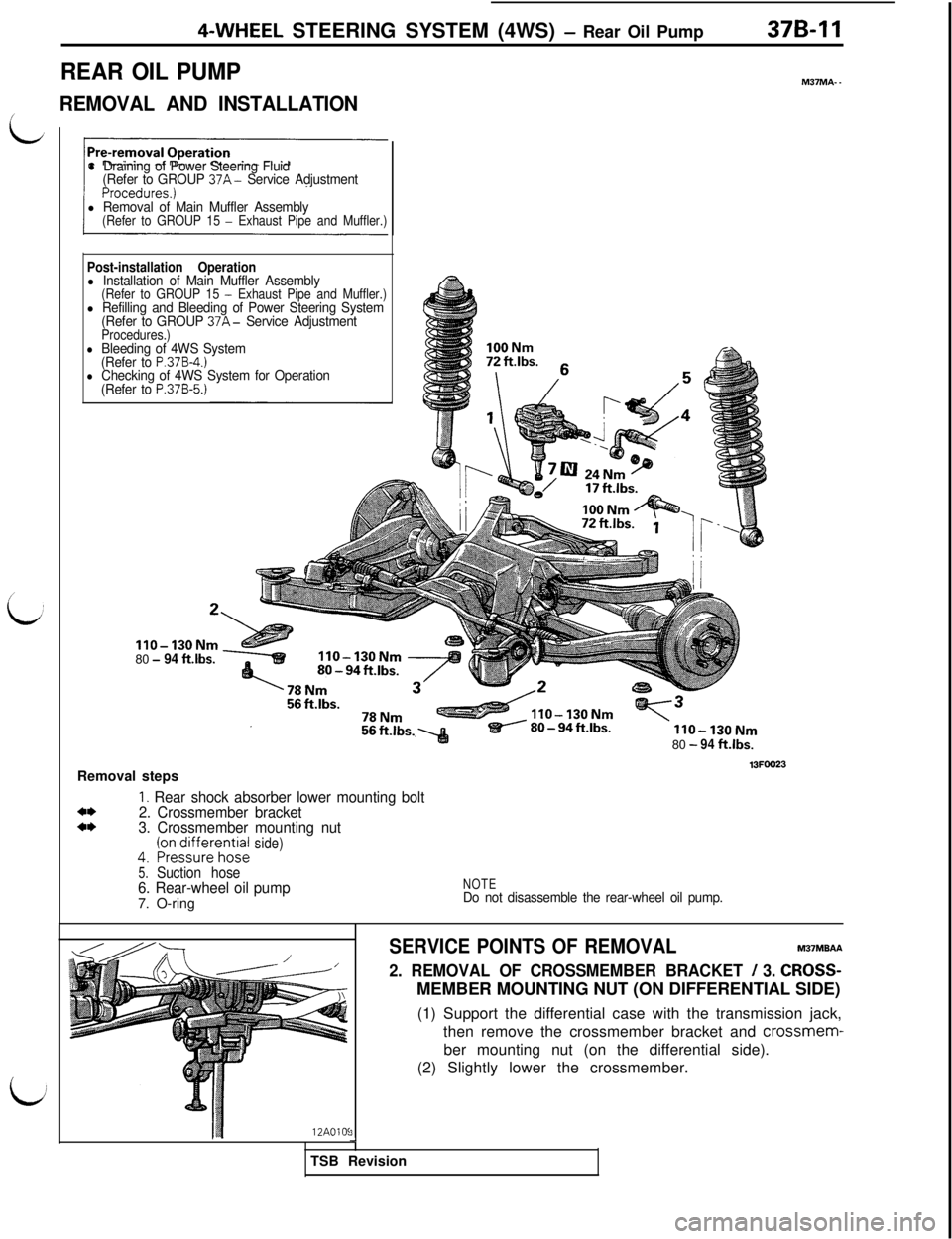
IIO-130Nm80- 94 ft.lbs.Removal steps
1. Rear shock absorber lower mounting bolt4*2. Crossmember bracketa*3. Crossmember mounting nut4.~rry~~,ff~h;t~Jside)
5.Suction hose6. Rear-wheel oil pump7. O-ring80
-94ft.lbs.
13FOO23
NOTEDo not disassemble the rear-wheel oil pump.
M3?MA- -12AOlOS
3
SERVICE POINTS OF REMOVALM37MBAA
2. REMOVAL OF CROSSMEMBER BRACKET / 3. CROSS-MEMBER MOUNTING NUT (ON DIFFERENTIAL SIDE)
(1) Support the differential case with the transmission jack,
then remove the crossmember bracket and crossmem-
ber mounting nut (on the differential side).
(2) Slightly lower the crossmember.
2TSB Revision
Page 1096 of 1146
CautionRefrigerantR-l 2iAdaptorNever use the high pressure side as this may cause
/valve
refrigerant to flow back, using rupture of the servicecan.(7) Start the engine. Charge valvergmg hose
55-14 HEATERS AND MANUAL AIR CONDITIONER - Service Adjustment procedures
CORRECTING LOW REFRIGERANT LEVEL
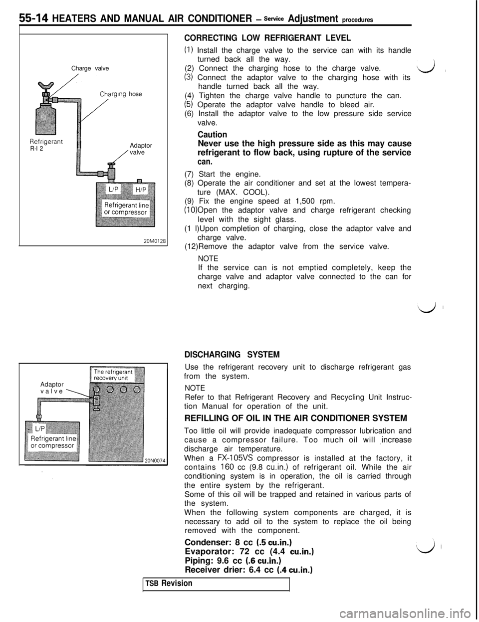
(I) Install the charge valve to the service can with its handle
turned back all the way.
(2) Connect the charging hose to the charge valve.
(3) Connect the adaptor valve to the charging hose with itsL&lhandle turned back all the way.
(4) Tighten the charge valve handle to puncture the can.
(5) Operate the adaptor valve handle to bleed air.
(6) Install the adaptor valve to the low pressure side service
valve.
(8) Operate the air conditioner and set at the lowest tempera-
ture (MAX. COOL).
(9) Fix the engine speed at 1,500 rpm.
(10)Open the adaptor valve and charge refrigerant checking
level with the sight glass.
(1 l)Upon completion of charging, close the adaptor valve and
20M0128charge valve.
(12)Remove the adaptor valve from the service valve.
NOTEIf the service can is not emptied completely, keep the
charge valve and adaptor valve connected to the can for
next charging.
Adaptor
valve
\
DISCHARGING SYSTEMUse the refrigerant recovery unit to discharge refrigerant gas
from the system.
NOTERefer to that Refrigerant Recovery and Recycling Unit Instruc-
tion Manual for operation of the unit.
REFILLING OF OIL IN THE AIR CONDITIONER SYSTEM
Too little oil will provide inadequate compressor lubrication and
cause a compressor failure. Too much oil will ,increase
discharge air temperature.
When a
FX-105VS compressor is installed at the factory, it
contains
160 cc (9.8 cu.in.) of refrigerant oil. While the air
conditioning system is in operation, the oil is carried through
the entire system by the refrigerant.
Some of this oil will be trapped and retained in various parts of
the system.
When the following system components are charged, it is
necessary to add oil to the system to replace the oil being
removed with the component.
Condenser: 8 cc
(5 cu.in.)Evaporator: 72 cc (4.4
cu.in.)Piping: 9.6 cc
(6 cu.in.)Receiver drier: 6.4 cc
(.4 cu.in.)
TSB Revision
Page 1110 of 1146
55-28HEATERS AND MANUAL AIR CONDITIONER - Comtxessor
20F0067
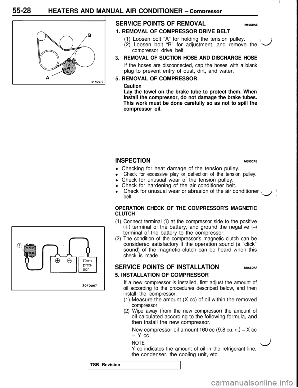
SERVICE POINTS OF REMOVALM55SBAE1. REMOVAL OF COMPRESSOR DRIVE BELT
(1) Loosen bolt “A” for holding the tension pulley.
(2) Loosen bolt “B” for adjustment, and remove the
‘J
compressor drive belt.
3.REMOVAL OF SUCTION HOSE AND DISCHARGE HOSE
If the hoses are disconnected, cap the hoses with a blankplug to prevent entry of dust, dirt, and water.
5. REMOVAL OF COMPRESSOR
Caution
Lay the towel on the brake tube to protect them. When
install the compressor, do not damage the brake tubes.
This work must be done carefully so as not to spill the
compressor oil.
INSPECTIONM55SCAEl Checking for heat damage of the tension pulley.
l
Check for excessive play or deflection of the tension pulley.l Check for unusual wear of the tension pulley.
l Check for hardening of the air conditioner belt.
lCheck for unusual wear or abrasion of the air conditioner ,
belt.
\d’
OPERATION CHECK OF THE COMPRESSOR’S MAGNETIC
CLUTCH
(1) Connect terminal @ at the compressor side to the positive
(+) terminal of the battery, and ground the negative (-)terminal of the battery to the compressor.
(2) The condition of the compressor’s magnetic clutch can beconsidered satisfactory if the operation sound (a “click”
sound) of the magnetic clutch can be heard when this
check is made.
SERVICE POINTS OF INSTALLATIONM55SDAF5. INSTALLATION OF COMPRESSOR
If a new compressor is installed, first adjust the amount of
oil according to the procedures described below, and then
install the compressor.(1) Measure the amount (X cc) of oil within the removed
compressor.
(2) Wipe away (from the new compressor) the amount ofoil calculated according to the following formula, and
then install the new compressor.
New compressor oil amount
160 cc (9.8 cu.in.) - X cc= Y cc
NOTE
Y cc indicates the amount of oil in the refrigerant line,l/jthe condenser, the cooling unit, etc.
TSB Revision
Page 1117 of 1146
HEATERS AND MANUAL AIR CONDITIONER - Rdrigerant Line55-35
REFRIGERANT LINE
/’REMOVAL AND INSTALLATION
L;Pre-removal and Post-installation Operation
l Discharge and Charging of Refrigerant(Refer to P.55-14, 11.)
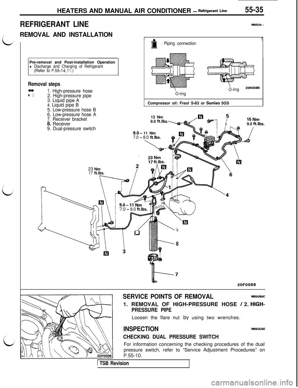
Removal steps
a*1. High-pressure hosel *2. High-pressure pipe
3. Liquid pipe A
4. Liquid pipe B
5. Low-pressure hose B
6. Low-pressure hose A
7. Receiver bracket
8. Receiver
9. Dual-pressure switch23 Nm
17 ft.lbs.-\-M55UA-
-
1: Piping connection
O-ring20N0089
1
O-ringCompressor oil: Freol S-83 or Suniso 5GS
13 Nm
9.0
ft.lbs.
9.0-11 Nm7.0 -8.0 ft.lbs.
\
TE NUTII” 1.1119.0 ft.lbs.
7.0 - 8.0 ft.lbs.
/
‘Ill
q9
8
2OFOO68
SERVICE POINTS OF REMOVALMIBUBAC
1. REMOVAL OF HIGH-PRESSURE HOSE
/ 2. HIGH-
PRESSURE PIPELoosen the flare nut ,by using two wrenches.
INSPECTIONMHUCAD
CHECKING DUAL PRESSURE SWITCHFor information concerning the checking procedures of the dual
pressure switch, refer to “Service Adjustment Procedures” on
P.55-10.
1 TSB Revision