jack points MITSUBISHI 3000GT 1991 Service Manual
[x] Cancel search | Manufacturer: MITSUBISHI, Model Year: 1991, Model line: 3000GT, Model: MITSUBISHI 3000GT 1991Pages: 1146, PDF Size: 76.68 MB
Page 340 of 1146
15-30 INTAKE AND EXHAUST -Exhaust Pipe, Main Muffler and Catalytic Converter
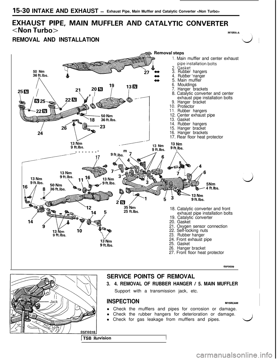
EXHAUST PIPE, MAIN MUFFLER AND CATALYTIC CONVERTER
REMOVAL AND INSTALLATION
1. Main muffler and center exhaust50 Nm36
Fbs.
I\
yil / \2: h2yR ‘i”
3. Rubber hangers, ,4. Rubber nanger5. Main muffler6.Mouldings7.Hanger brackets8. Catalytic converter and center
exhaust pipe installation bolts
9.Hanger bracket10.Protector11.Rubber hangers12. Center exhaust pipe13.Gasket
---------179fl
/-r
9 ftlbs./----------------m _
I
!
14. Rubber hangers
15. Hanger bracket
16. Hanger brackets
17. Rear floor heat protector13 Nm
13 Nm
9 ftlbs.9 ft,lbs.5Nm
4 ft.lbs.
35hlm
25 ft.lbs.18. Catalytic converter and front
exhaust pipe installation bolts
19. Catalytic converter
20. Gasket
21. Oxygen sensor connection
22. Self-locking nuts9
ft.lbs.\/23.Rubberhanger24. Front exhaust pipe25.Gasket26.Hangerbracket27. Front floor heat protector
05FOO39
SERVICE POINTS OF REMOVAL
3.4. REMOVAL OF RUBBER HANGER / 5. MAIN MUFFLERSupport with a transmission jack, etc.
INSPECTIONMlSRCAM
l Check the mufflers and pipes for corrosion or damage.
l Check the rubber hangers for deterioration or damage.
l Check for gas leakage from mufflers and pipes.wision
1
L.J
Page 342 of 1146
15-32 INTAKE AND EXHAUST -Exhaust Pipe, Main Muffler and Catalytic Converter
SERVICE POINTS OF REMOVALMlBRBAA
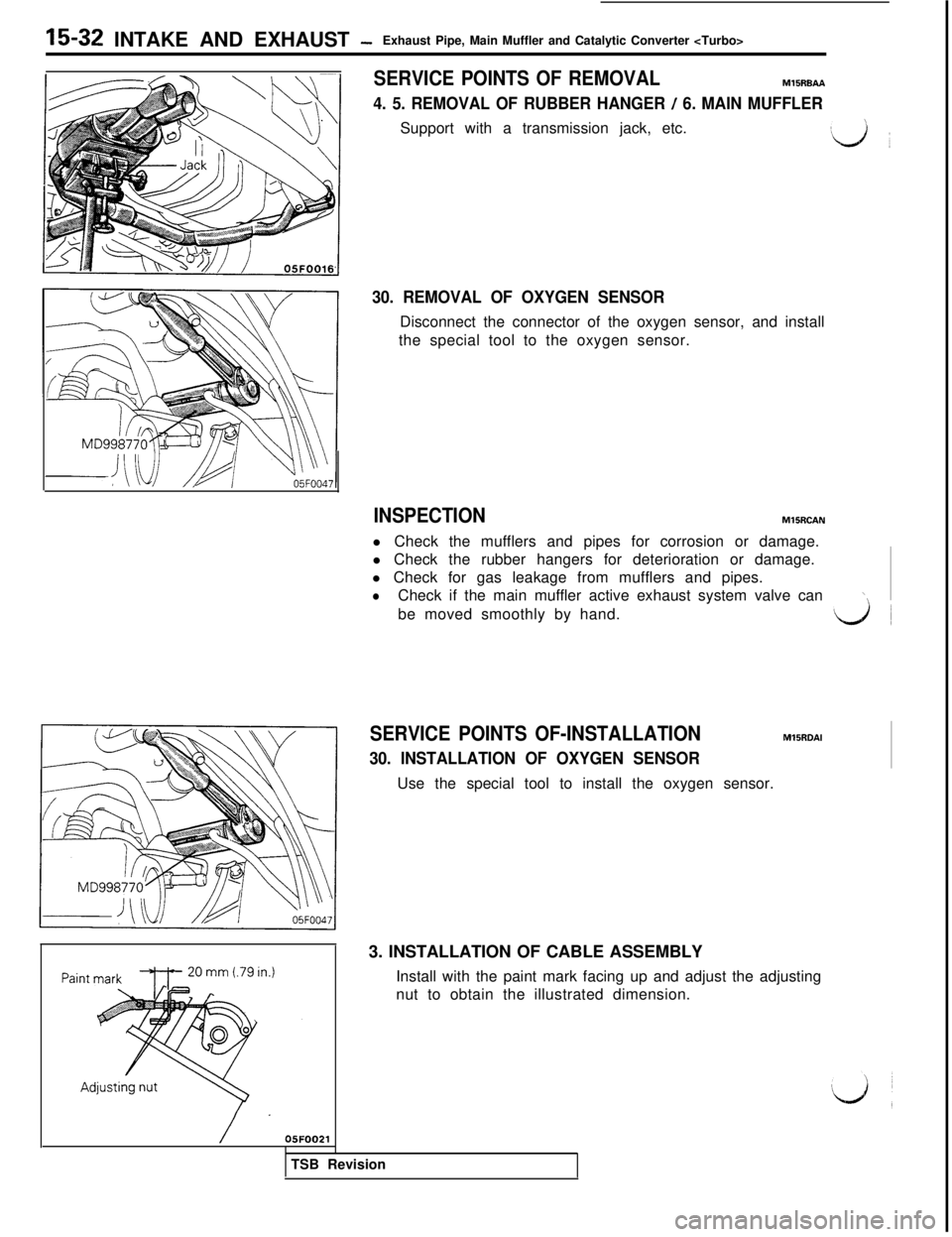
4. 5. REMOVAL OF RUBBER HANGER / 6. MAIN MUFFLERSupport with a transmission jack, etc.
:iJ ~
30. REMOVAL OF OXYGEN SENSORDisconnect the connector of the oxygen sensor, and install
the special tool to the oxygen sensor.
INSPECTIONMlSRCAN
l Check the mufflers and pipes for corrosion or damage.
l Check the rubber hangers for deterioration or damage.
l Check for gas leakage from mufflers and pipes.
lCheck if the main muffler active exhaust system valve can\\be moved smoothly by hand.
SERVICE POINTS OF-INSTALLATIONMllRDAl
30. INSTALLATION OF OXYGEN SENSORUse the special tool to install the oxygen sensor.
3. INSTALLATION OF CABLE ASSEMBLY
Install with the paint mark facing up and adjust the adjusting
nut to obtain the illustrated dimension.
TSB Revision
Page 397 of 1146
MANUAL TRANSAXLE
Transaxmount
bracket
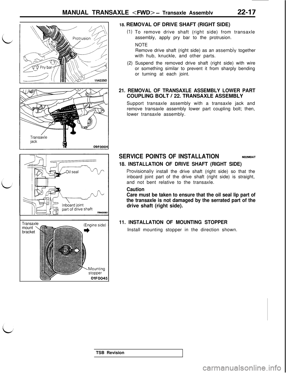
OlFOO4518. REMOVAL OF DRIVE SHAFT (RIGHT SIDE)
(1) To remove drive shaft (right side) from transaxle
assembly, apply pry bar to the protrusion.
NOTERemove drive shaft (right side) as an
assemb’ly together
with hub, knuckle, and other parts.
(2) Suspend the removed drive shaft (right side) with wire
or something similar to prevent it from sharply bending
or turning at each joint.
21. REMOVAL OF TRANSAXLE ASSEMBLY LOWER PARTCOUPLING BOLT
/ 22. TRANSAXLE ASSEMBLY
Support transaxle assembly with a transaxle jack and
remove transaxle assembly lower part coupling bolt; then,
lower transaxle assembly.
SERVICE POINTS OF INSTALLATIONM2ZMDAT
18. INSTALLATION OF DRIVE SHAFT (RIGHT SIDE)
ProvisionaHy install the drive shaft (right side) so that the
inboard joint part of the drive shaft (right side) is straight,
and not bent relative to the transaxle.
Caution
Care must be taken to ensure that the oil seal lip part of
the transaxle is not damaged by the serrated part of thedrive shaft (right side).
11. INSTALLATION OF MOUNTING STOPPERInstall mounting stopper in the direction shown.
TSB Revision
Page 515 of 1146
LJ
LAUTOMATIC TRANSAXLE
- Transaxle Assembly
23-63 ’
31 Nm‘?“.75
Nm75 Nm60- 72Nm54 ftlbs.
43
- 52ft.lbs.I
14II
60-72Nm\20
Ia15
26
). C-J\
\23j5 Nm64ft.lbs.15’
1636 Nm43-G,“.%S.26
ft.lbs.
OSFOOBH
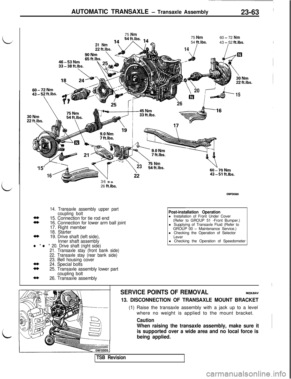
14. Transaxle assembly upper part
coupling bolt
4*15. Connection for tie rod end4*16. Connection for lower arm ball joint
17. Right member
18. Starter
4*19. Drive shaft (left side),
Inner shaft assembly
l * l * 20. Drive shaft (right side)
21. Transaxle stay (front bank side)
22. Transaxle stay (rear bank side)
23. Bell housing cover4*24. Special bolts4*25. Transaxle assembly lower part
coupling bolt
4*26. Transaxle assemblyPost-installation Operationl Installation of Front Under Cover
(Refer to GROUP 51 -Front Bumper.)
l Supplying of Transaxle Fluid (Refer to
GROUP 00
- Maintenance Service.)
l Checking the Operation of Selector
Lever
l Checking the Operation of Speedometer
SERVICE POINTS OF REMOVALM22kBAV
13. DISCONNECTION OF TRANSAXLE MOUNT BRACKET(1) Raise the transaxle assembly with a jack up to a level
where no weight is applied to the mount bracket.
Caution
When raising the transaxle assembly, make sure it
is supported over a wide area and no local force is
being applied.
TSB Revision
Page 516 of 1146
23-64
AUTOMATIC, TRANSAXLE - Transaxle Assembly
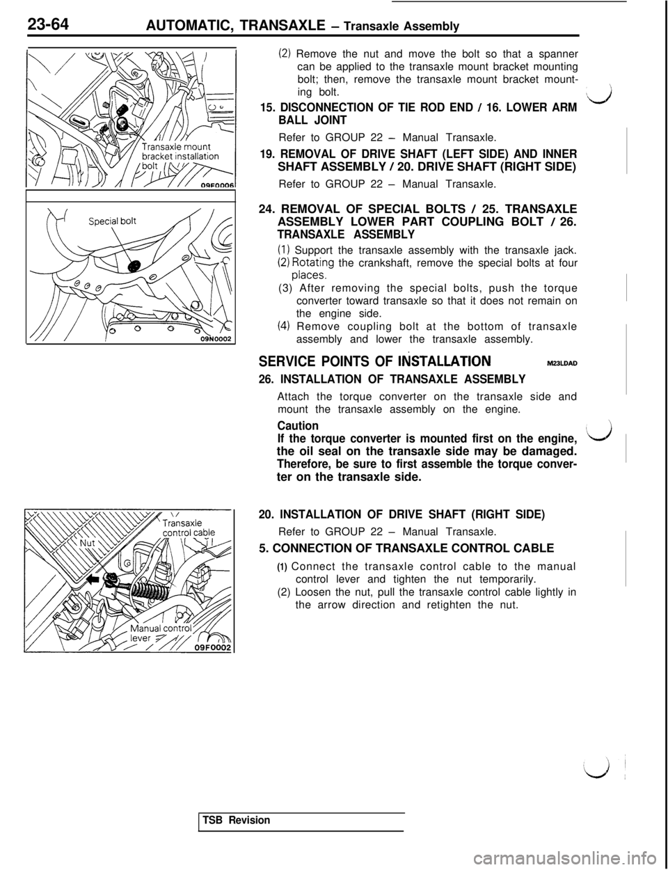
(2) Remove the nut and move the bolt so that a spanner
can be applied to the transaxle mount bracket mounting
bolt; then, remove the transaxle mount bracket mount-
ing bolt.
15. DISCONNECTION OF TIE ROD END / 16. LOWER ARM$3
BALL JOINTRefer to GROUP 22
- Manual Transaxle.
19. REMOVAL OF DRIVE SHAFT (LEFT SIDE) AND INNERSHAFT ASSEMBLY
/ 20. DRIVE SHAFT (RIGHT SIDE)
Refer to GROUP 22
- Manual Transaxle.
24. REMOVAL OF SPECIAL BOLTS
/ 25. TRANSAXLE
ASSEMBLY LOWER PART COUPLING BOLT
/ 26.
TRANSAXLE ASSEMBLY
(1) Support the transaxle assembly with the transaxle jack.
(2) ;;F;ng the crankshaft, remove the special bolts at four
(3) After removing the special bolts, push the torque
converter toward transaxle so that it does not remain on
the engine side.
(4) Remove coupling bolt at the bottom of transaxle
assembly and lower the transaxle assembly.
SERVICE POINTS OF IliSTALLATlONM23LDAD
26. INSTALLATION OF TRANSAXLE ASSEMBLYAttach the torque converter on the transaxle side and
mount the transaxle assembly on the engine.
Caution
If the torque converter is mounted first on the engine,
Idthe oil seal on the transaxle side may be damaged.
Therefore, be sure to first assemble the torque conver-ter on the transaxle side.
20. INSTALLATION OF DRIVE SHAFT (RIGHT SIDE)Refer to GROUP 22
- Manual Transaxle.
5. CONNECTION OF TRANSAXLE CONTROL CABLE
(1) Connect the transaxle control cable to the manual
control lever and tighten the nut temporarily.
(2) Loosen the nut, pull the transaxle control cable lightly in
the arrow direction and retighten the nut.
TSB Revision
Page 693 of 1146
REAR SUSPENSION
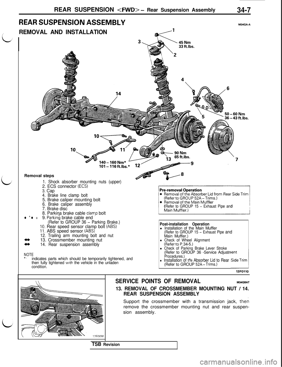
REAR SUSPENSION ASSEMBLYM34GA-A
L/
REMOVAL AND INSTALLATION
140- 160 Nm*IOI- 116ftlbs.
Removal steps
1. Shock absorber mounting nuts (upper)2. ECS connector (ECS)3. Cap4. Brake line clamp bolt5. Brake caliper mounting bolt6. Brake caliper assembly7. Brake disc
8. Parkina brake cable clamo bolt
(Refer to GROUP 15 - Exhaust Pipe and
l * l +9. ParkinG brake cable end ”(Refer to GROUP 36 - Parking Brake.)10. Rear speed sensor clamp bolt (ABS)11. ABS speed sensor (ABS)12. Trailing arm mounting bolt and nut*I)13. Crossmember mounting nut*I)14. Rear suspension assembly
NOTE*.indicates parts which should be temporarily tightened, and
then fully tightened with the vehicle in the unladencondition.
Post-installation Operationl Installation of the Main Muffler(Refer to GROUP 15 - Exhaust Pipe andMain Muffler.)l Check of Wheel Alignment(Refer.to P.34-5.)l Check of Parking Brake Lever Stroke(Refer to GROUP 36 -Service AdjustmentProcedures.)l Installation of the Absorber Lid to Rear Side Trim(Refer to GROUP 52A-Trims.)A12FOllO
SERVICE POINTS OF REMOVALM34GBAT
13. REMOVAL OF CROSSMEMBER MOUNTING NUT / 14.
REAR SUSPENSION ASSEMBLYSupport the crossmember with a transmission jack, then
remove the crossmember mounting nut and rear suspen-
sion assembly.
TSB Revision
Page 711 of 1146
REAR SUSPENSION
Dust shield12A022i
Press outMB991 387
MB991 38812N008E
Press-fitMB991 387
MB99089012N008f
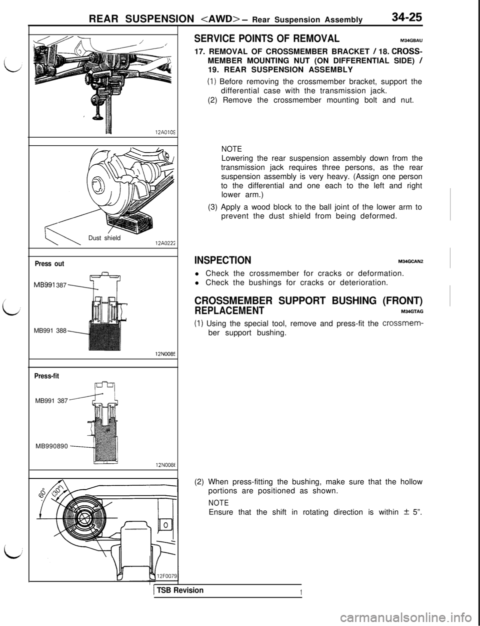
SERVICE POINTS OF REMOVALM34GBAU17. REMOVAL OF CROSSMEMBER BRACKET
/ 18. CROSS-
MEMBER MOUNTING NUT (ON DIFFERENTIAL SIDE)
/19. REAR SUSPENSION ASSEMBLY
(1) Before removing the crossmember bracket, support the
differential case with the transmission jack.
(2) Remove the crossmember mounting bolt and nut.
NOTELowering the rear suspension assembly down from the
transmission jack requires three persons, as the rear
suspension assembly is very heavy. (Assign one person
to the differential and one each to the left and right
lower arm.)
(3) Apply a wood block to the ball joint of the lower arm to
prevent the dust shield from being deformed.
INSPECTIONM34GCAN2l Check the crossmember for cracks or deformation.
l Check the bushings for cracks or deterioration.
CROSSMEMBER SUPPORT BUSHING (FRONT)
REPLACEMENTM34GTAG
(1) Using the special tool, remove and press-fit the crossmem-
ber support bushing.
(2) When press-fitting the bushing, make sure that the hollow
portions are positioned as shown.
NOTEEnsure that the shift in rotating direction is within
+ 5”.
1 TSB Revision1
Page 721 of 1146
REAR SUSPENSION
----
-7
--;:-
hIlll~~II’
L IT ;
E!
.’
,.GLZ,
?,,..,”il.//,:”, /.’
\12AOll'Clip r&g
h12LO24'
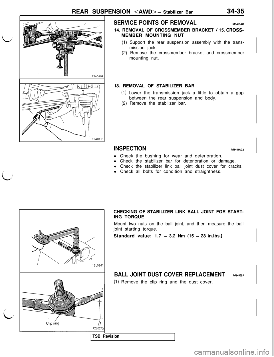
SERVICE POINTS OF REMOVALM34lDAC
14. REMOVAL OF CROSSMEMBER BRACKET
/ 15. CROSS-MEMBER MOUNTING NUT
(1) Support the rear suspension assembly with the trans-
mission jack.
(2) Remove the crossmember bracket and crossmember
mounting nut.
18. REMOVAL OF STABILIZER BAR
(1) Lower the transmission jack a little to obtain a gap
between the rear suspension and body.
(2) Remove the stabilizer bar.
INSPECTIONM341BACZ
l Check the bushing for wear and deterioration.
l Check the stabilizer bar for deterioration or damage.
l Check the stabilizer link ball joint dust cover for cracks.
l Check all bolts for condition and straightness.
CHECKING OF STABILIZER LINK BALL JOINT FOR START-
ING TORQUE
Mount two nuts on the ball joint, and then measure the ball
joint starting torque.
Standard value: 1.7
- 3.2 Nm (15 - 28 in.lbs.)
BALL JOINT DUST COVER REPLACEMENTM34lEBA
(1) Remove the clip ring and the dust cover.
TSB Revision
Page 780 of 1146
35-58SERVICE BRAKES - Service Adjustment Procedures
POINTS IN WAVEFORM MEASUREMENT
Symptom
Too small or zero waveform
amplitudeProbable causes
Faulty wheel speed sensorRemedy
Replace sensor
Incorrect pole piece-to-rotor clearance
Adjust clearance
Waveform amplitude fluctuates
excessively (this is no problem ifAxle hub eccentric or with large runout
Replace hub
the minimum amplitude is
100 mV
or more)
Noisy or disturbed waveformOpen circuit in sensor
Open circuit in harness
Incorrectly mounted wheel speed sensor
Rotor with missing or damaged teethReplace sensor
Correct harness
Mount correctly
Replace rotor
NOTEThe wheel speed sensor cable moves following motion of the front or rear suspension. Therefore, it is likely that it has an
open circuit only when driving on rough roads and it functions normally on ordinary roads. It is, therefore, recommended
to observe sensor output voltage waveform also under special conditions, such as rough road driving,
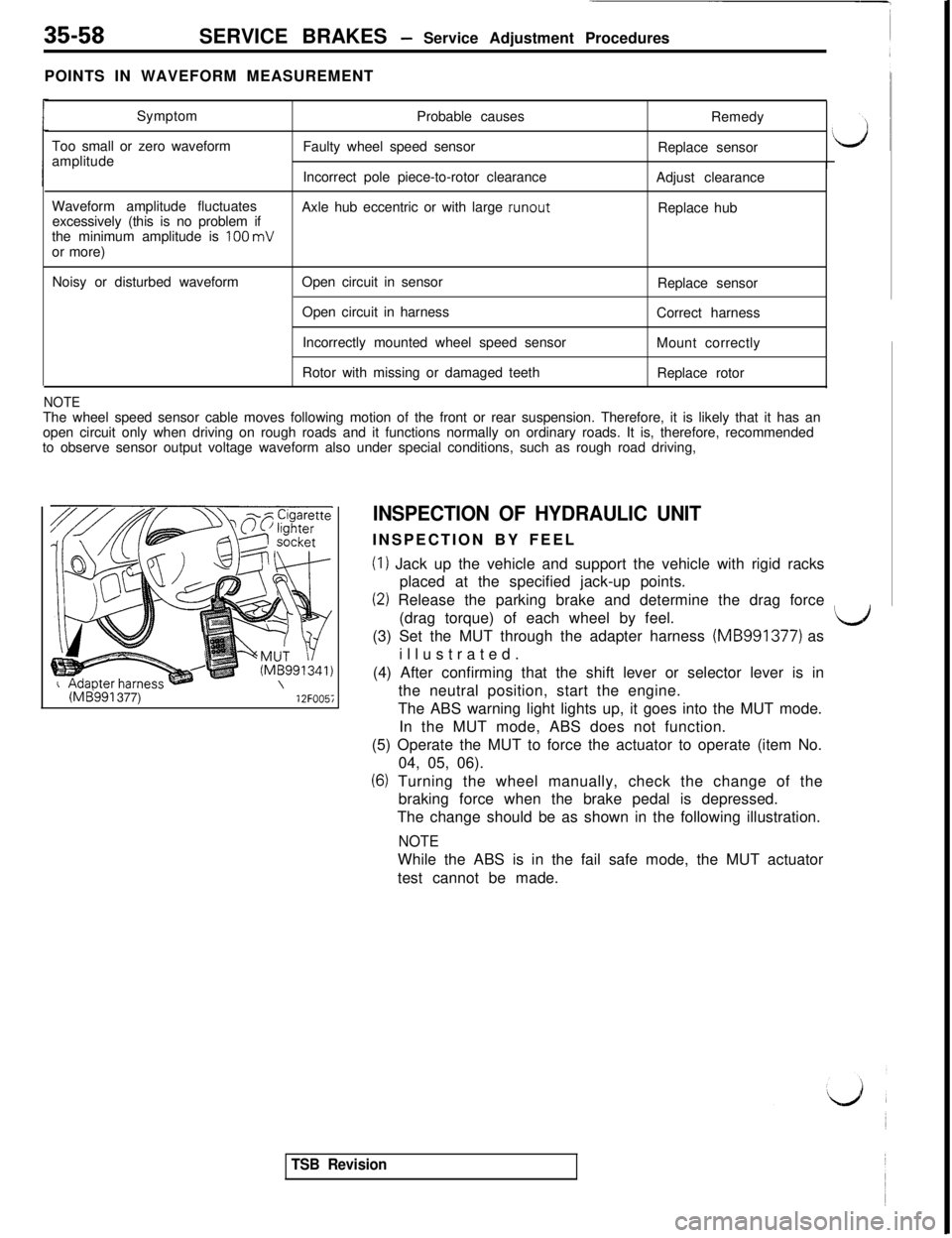
(ME!991 377)12FOO5i
INSPECTION OF HYDRAULIC UNITINSPECTION BY FEEL
(I) Jack up the vehicle and support the vehicle with rigid racks
placed at the specified jack-up points.
(2) Release the parking brake and determine the drag force
(drag torque) of each wheel by feel.
LJ(3) Set the MUT through the adapter harness (MB991377) as
illustrated.
(4) After confirming that the shift lever or selector lever is in
the neutral position, start the engine.
The ABS warning light lights up, it goes into the MUT mode.
In the MUT mode, ABS does not function.
(5) Operate the MUT to force the actuator to operate (item No.
04, 05, 06).
(6) Turning the wheel manually, check the change of the
braking force when the brake pedal is depressed.
The change should be as shown in the following illustration.
NOTEWhile the ABS is in the fail safe mode, the MUT actuator
test cannot be made.
TSB Revision
Page 867 of 1146
4-WHEEL STEERING SYSTEM (4WS) - Power Cylinder378-712AOlOE
IlZAO2;91
3A009
Wire
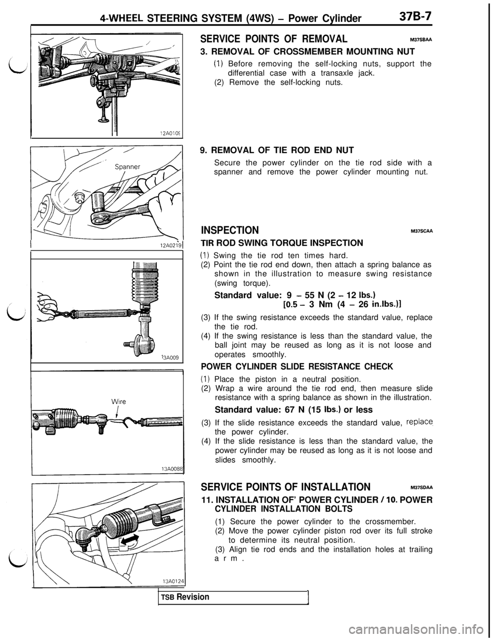
SERVICE POINTS OF REMOVALM37SBM3. REMOVAL OF CROSSMEMBER MOUNTING NUT
(1) Before removing the self-locking nuts, support the
differential case with a transaxle jack.
(2) Remove the self-locking nuts.
9. REMOVAL OF TIE ROD END NUT
Secure the power cylinder on the tie rod side with a
spanner and remove the power cylinder mounting nut.
INSPECTIONM37SCM
TIR ROD SWING TORQUE INSPECTION
(1) Swing the tie rod ten times hard.
(2) Point the tie rod end down, then attach a spring balance as
shown in the illustration to measure swing resistance
(swing torque).
Standard value: 9
- 55 N (2 - 12 Ibs.)
[0.5 - 3 Nm (4 - 26 in.lbs.)l(3) If the swing resistance exceeds the standard value, replace
the tie rod.
(4) If the swing resistance is less than the standard value, the
ball joint may be reused as long as it is not loose and
operates smoothly.
POWER CYLINDER SLIDE RESISTANCE CHECK
(1) Place the piston in a neutral position.
(2) Wrap a wire around the tie rod end, then measure slide
resistance with a spring balance as shown in the illustration.
Standard value: 67 N (15
Ibs.) or less
(3) If the slide resistance exceeds the standard value,
replace,the power cylinder.
(4) If the slide resistance is less than the standard value, the
power cylinder may be reused as long as it is not loose and
slides smoothly.
SERVICE POINTS OF INSTALLATIONM37SDP911. INSTALLATION OF’ POWER CYLINDER
/ 10. POWER
CYLINDER INSTALLATION BOLTS(1) Secure the power cylinder to the crossmember.
(2) Move the power cylinder piston rod over its full stroke
to determine its neutral position.
(3) Align tie rod ends and the installation holes at trailing
arm.
TSB RevisionI