power steering fluid MITSUBISHI 3000GT 1991 Service Manual
[x] Cancel search | Manufacturer: MITSUBISHI, Model Year: 1991, Model line: 3000GT, Model: MITSUBISHI 3000GT 1991Pages: 1146, PDF Size: 76.68 MB
Page 31 of 1146
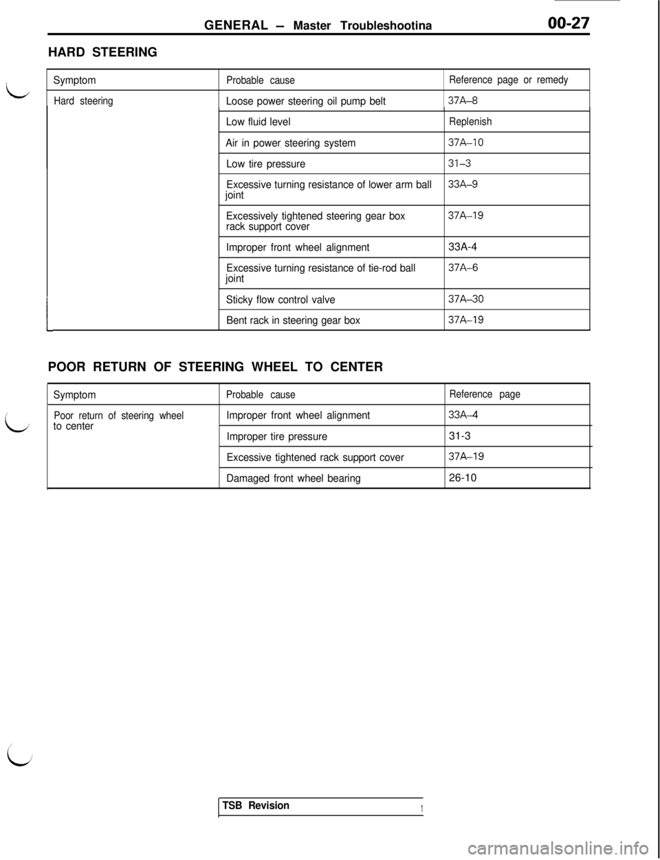
GENERAL - Master Troubleshootina00-27HARD STEERING
L
L
Symptom
Hard steeringProbable causeLoose power steering oil pump belt
Reference page or remedy37A-8
1POOR RETURN OF STEERING WHEEL TO CENTER
Symptom
Poor return of steering wheelto center
Probable cause
Improper front wheel alignment
Improper tire pressure
Excessive tightened rack support cover
Damaged front wheel bearing
Reference page33A-4
31-3
37A-1926-10
Low fluid levelReplenish
Air in power steering system37A-10
Low tire pressure
313
Excessive turning resistance of lower arm ball33A-9joint
Excessively tightened steering gear box
rack support cover
37A-19
Improper front wheel alignment
Excessive turning resistance of tie-rod ball
joint
Sticky flow control valve
Bent rack in steering gear box33A-437A-6
37A-30
37A-19
TSB Revision1
Page 76 of 1146
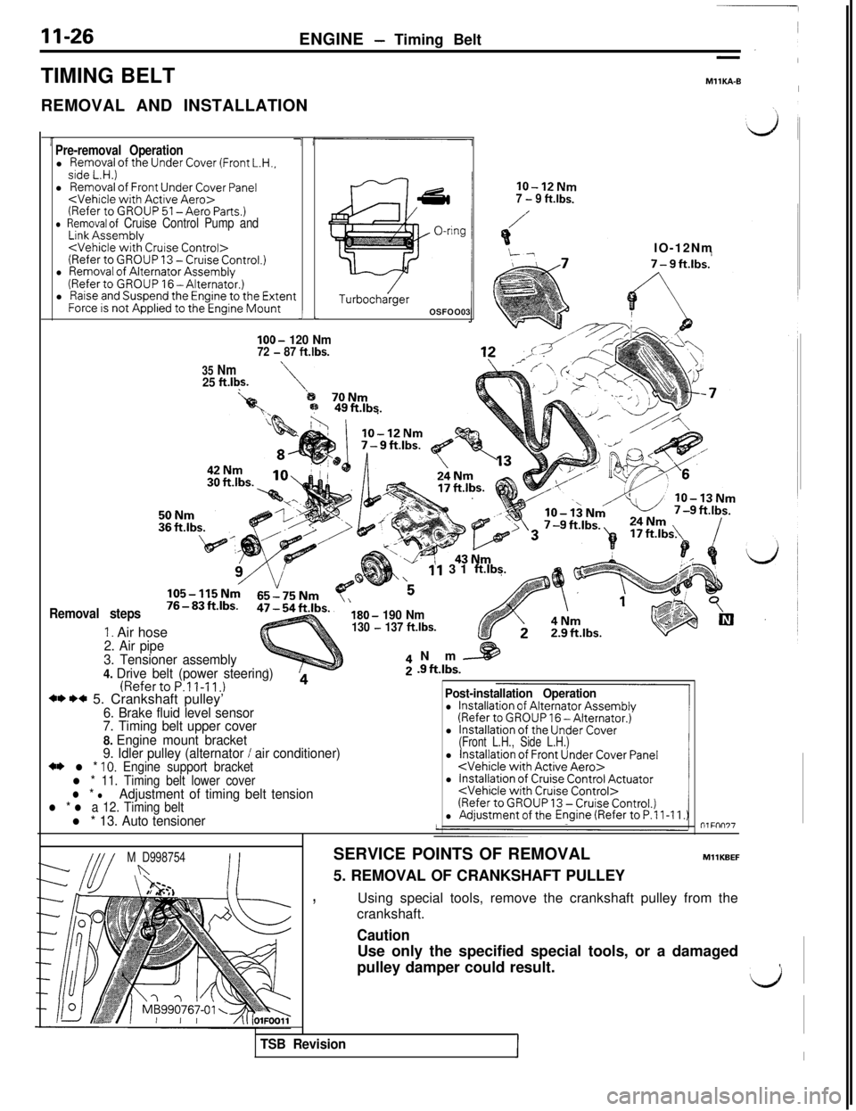
11-26ENGINE - Timing Belt
TIMING BELT
REMOVAL AND INSTALLATION
MllKA-BI
Pre-removal Operationl Removal of the Under Cover (Front L.H.,side L.H.)l Removal of Front Under Cover Panel
l Raise and Suspend the Engine to the ExtentForce is not Applied to the Engine Mounti LIOO-
120 Nm72 - 87 ft.lbs.
35 Nm25 ft.l$.
TurbochargerOSFOO03
lo-12Nm7 - 9 ft.lbs.
Removal steps
1. Air hose
11 31 ftlbs.
‘5IO-12Nm
B;p 49ftJbs.
\
180- 190 Nm130 - 137 ft.lbs.
2. Air pipe
3. Tensioner assembly
4. Drive belt (power steering)
(RefertoP.ll-11.)4** I)* 5. Crankshaft pulley’6. Brake fluid level sensor
7. Timing belt upper cover
8. Engine mount bracket
9. Idler pulley (alternator
/ air conditioner)+* l * 10. Engine support bracketl * 11. Timing belt lower coverl * lAdjustment of timing belt tensionl * l a 12. Timing beltl * 13. Auto tensionerNm
[email protected].
Post-installation Operation
l Installation of Alternator Assembly(Refer to GROUP 16 -Alternator.)
l Installation of the Under Cover(Front L.H., Side L.H.)l Installation of Front Under Cover Panel
l Installation of Cruise Control Actuator
M D998754nSERVICE POINTS OF REMOVAL
5. REMOVAL OF CRANKSHAFT PULLEYMllKBEF
,Using special tools, remove the crankshaft pulley from the
crankshaft.
TSB RevisionII
CautionUse only the specified special tools, or a damaged
pulley damper could result.
,
LJ
Page 648 of 1146
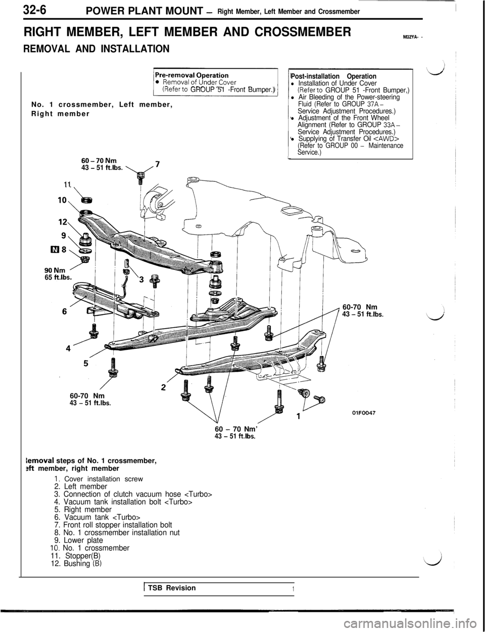
32-6POWER PLANT MOUNT -Right Member, Left Member and Crossmember
RIGHT MEMBER, LEFT MEMBER AND CROSSMEMBER
I
M32YA- _
REMOVAL AND INSTALLATION
(Referto GROUP 51 -Front Bumper.)No. 1 crossmember, Left member,
Right member
60-70Nm43 - 51 ft.lbs.
11
F=----lL90Nm
’65 ft.lbs.
/I
Post-installation Operationl Installation of Under Cover(Referto GROUP 51 -Front Bumper,)l Air Bleeding of the Power-steeringFluid (Refer to GROUP 37A-Service Adjustment Procedures.)l Adjustment of the Front Wheel
Alignment (Refer to GROUP 33A-Service Adjustment Procedures.)l Supplying of Transfer Oil
Service.)60-70 Nm
43 - 51 ft.lbs.60-70 Nm
43 - 51 ftlbs.
/aa lVOiFOO4760
- 70 Nm’43 - 51 ft.lbs.lemoval steps of No. 1 crossmember,
M member, right member
I. Cover installation screw2. Left member
3. Connection of clutch vacuum hose
4. Vacuum tank installation bolt
5. Right member
6. Vacuum tank
7. Front roll stopper installation bolt
8. No. 1 crossmember installation nut
9. Lower plate
10. No. 1 crossmember
11. Stopper(B)
12. Bushing
(B)
1 TSB Revision1
Page 829 of 1146
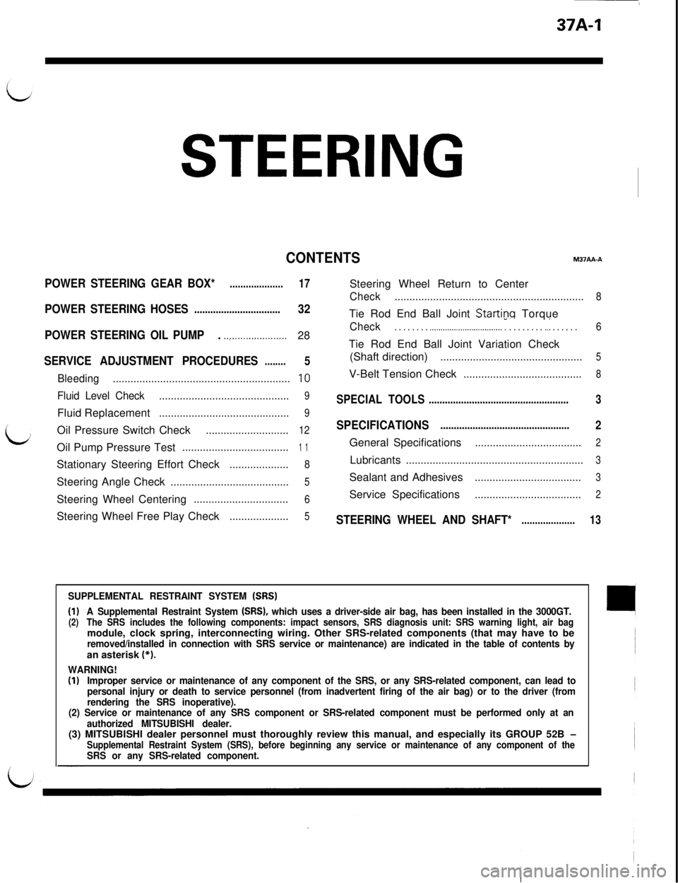
37A-1
STEERING
CONTENTSM37AA-A
POWER STEERING GEAR BOX*....................17Steering Wheel Return to Center
Check................................................................8
POWER STEERING HOSES................................32Tie Rod End Ball Joint Startinq Torque
POWER STEERING OIL PUMP. .._....................28Check. . . . . . . . .._.............................. r . . . . . . . . ..I . . . . . .6Tie Rod End Ball Joint Variation Check
SERVICE ADJUSTMENT PROCEDURES5(Shaft direction)................................................5........
Bleeding............................................................10V-Belt Tension Check........................................8
Fluid Level Check............................................9SPECIAL TOOLS....................................................3Fluid Replacement
............................................9
/
bOil Pressure Switch Check
SPECIFICATIONS2............................12................................................Oil Pump Pressure Test
....................................1 1General Specifications....................................2Stationary Steering Effort Check
....................8Lubricants............................................................3Steering Angle Check
5Sealant and Adhesives....................................3........................................Steering Wheel Centering
6Service Specifications....................................2................................Steering Wheel Free Play Check
....................5STEERING WHEEL AND SHAFT*....................13
SUPPLEMENTAL RESTRAINT SYSTEM (SRS)
(1)A Supplemental Restraint System (SRS), which uses a driver-side air bag, has been installed in the 3000GT.(2)The SRS includes the following components: impact sensors, SRS diagnosis unit: SRS warning light, air bagmodule, clock spring, interconnecting wiring. Other SRS-related components (that may have to be
removed/installed in connection with SRS service or maintenance) are indicated in the table of contents byan asterisk (*).
WARNING!(I)Improper service or maintenance of any component of the SRS, or any SRS-related component, can lead to
personal injury or death to service personnel (from inadvertent firing of the air bag) or to the driver (from
rendering the SRS inoperative).
(2) Service or maintenance of any SRS component or SRS-related component must be performed only at an
authorized MITSUBISHI dealer.(3) MITSUBISHI dealer personnel must thoroughly review this manual, and especially its GROUP 52B
-Supplemental Restraint System (SRS), before beginning any service or maintenance of any component of theSRS or any SRS-related component.
Page 831 of 1146
STEERING -Specifications / Special Tools37A-3
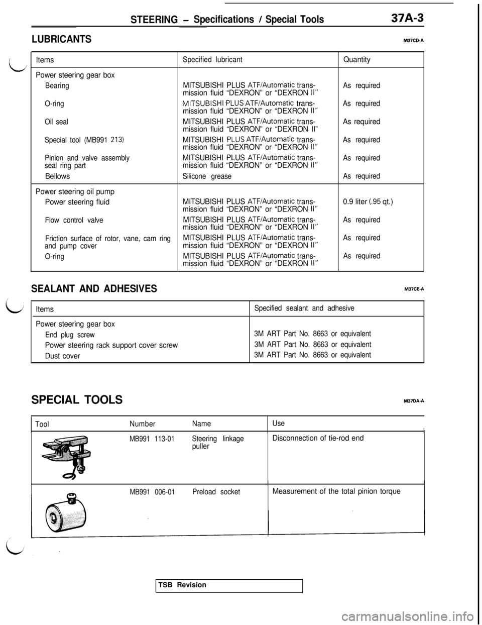
LUBRICANTSM37CD-A
L
/
b
ItemsSpecified lubricantQuantity
Power steering gear box
BearingMITSUBISHI PLUS ATF/Automatic trans-As requiredmission fluid “DEXRON” or “DEXRON II”
O-ringMlTSUBlSHl.PLUS ATF/Automatic trans-As requiredmission fluid “DEXRON” or “DEXRON II”
Oil sealMITSUBISHI PLUS ATF/Automatic trans-As required
mission fluid “DEXRON” or “DEXRON II”
Special tool (MB991 213)MITSUBISHI PLUSATFIAutomatic trans-As requiredmission fluid “DEXRON” or “DEXRON II”
Pinion and valve assemblyMITSUBISHI PLUS ATF/Automatic trans-As required
seal ring partmission fluid “DEXRON” or “DEXRON II”
BellowsSilicone greaseAs required
Power steering oil pump
Power steering fluidMITSUBISHI PLUS
ATF/Automatic trans-0.9 liter (.95 qt.)
mission fluid “DEXRON” or “DEXRON II”
Flow control valveMITSUBISHI PLUS ATF/Automatic trans-As requiredmission fluid “DEXRON” or “DEXRON II”
Friction surface of rotor, vane, cam ringMITSUBISHI PLUS ATF/Automatic trans-As required
and pump covermission fluid “DEXRON” or “DEXRON II”
O-ringMITSUBISHI PLUS ATF/Automatic trans-As requiredmission fluid “DEXRON” or “DEXRON II”
SEALANT AND ADHESIVESM37CE-A
Items
Power steering gear box
End plug screw
Power steering rack support cover screw
Dust cover
Specified sealant and adhesive
3M ART Part No. 8663 or equivalent
3M ART Part No. 8663 or equivalent
3M ART Part No. 8663 or equivalent
SPECIAL TOOLSM37DA.A
ToolNumberNameUseII
MB991 113-01Steering linkage
pullerDisconnection of tie-rod end
MB991 006-01Preload socketMeasurement of the total pinion torqueTSB Revision
Page 845 of 1146
STEERING- Power Steering Gear Box
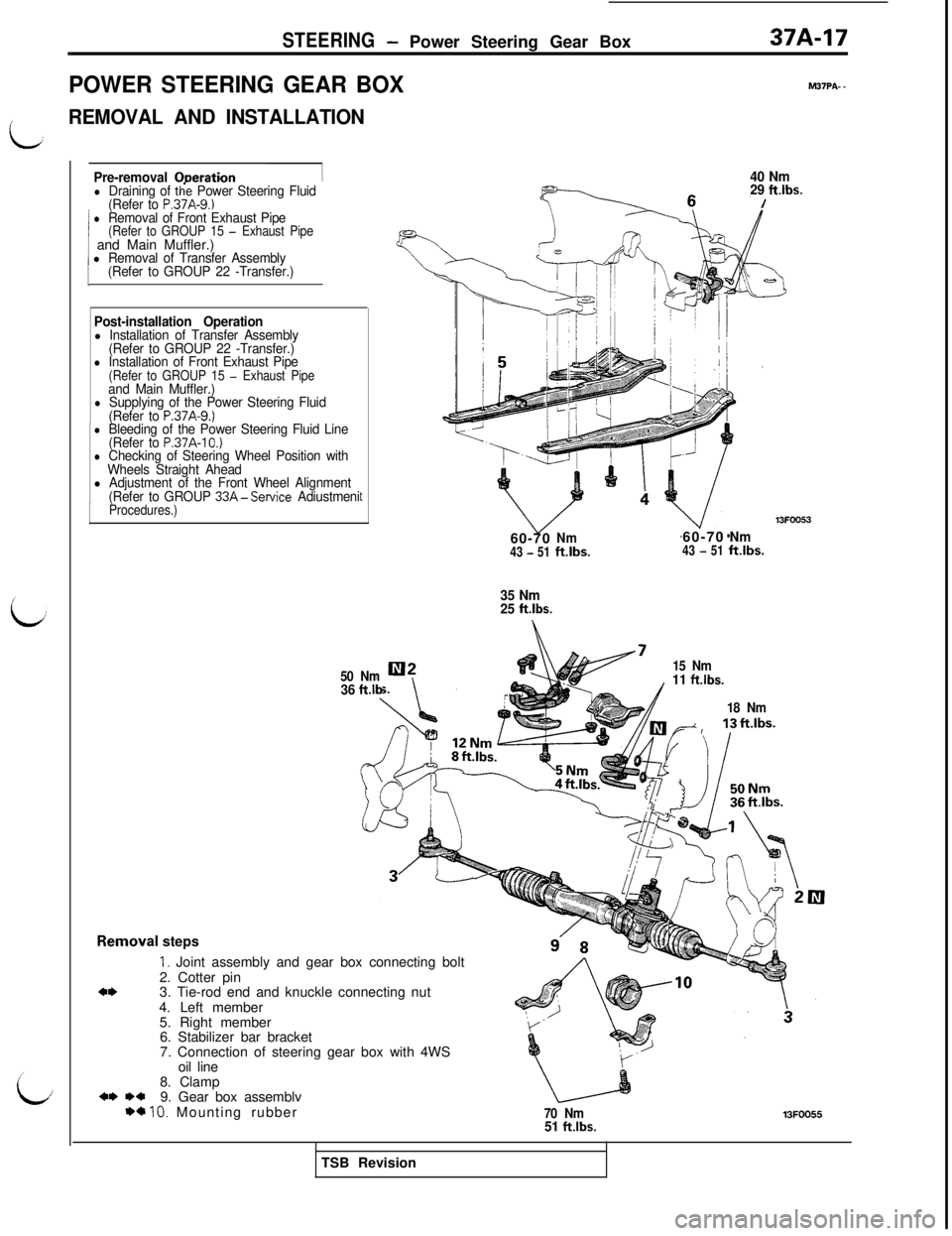
POWER STEERING GEAR BOX
/REMOVAL AND INSTALLATION37A-17
M37PA- -
i
i/
Pre-removal ODerationl Draining of the Power Steering Fluid
(Refer to P.37A-9.)l Removal of Front Exhaust Pipe(Refer to GROUP 15 - Exhaust Pipe1 and Main Muffler.)1l Removal of Transfer Assembly
(Refer to GROUP 22 -Transfer.)
Post-installation Operationl Installation of Transfer Assembly
(Refer to GROUP 22 -Transfer.)
l Installation of Front Exhaust Pipe(Refer to GROUP 15 - Exhaust Pipeand Main Muffler.)l Supplying of the Power Steering Fluid
(Refer to P.37A-9.)l Bleeding of the Power Steering Fluid Line
(Refer to P.37A-IO.)l Checking of Steering Wheel Position with
Wheels Straight Ahead
l Adjustment of the Front Wheel Alignment
(Refer to GROUP 33A-Service AdiustmeniProcedures.)Removt
50 Nm
c40 Nm
29 ftlbs.
/60-70
Nm43 - 51ft.lbs.60-70Nm43 - 51ft.lbs.
36
ft.lb
35 Nm
25 ft.lbs.
15 Nm
11 ftlbs.
18 Nm
lal steps
1. Joint assembly and gear box connecting bolt
2. Cotter pin
3. Tie-rod end and knuckle connecting nut
4. Left member
5. Right member
6. Stabilizer bar bracket
7. Connection of steering gear box with 4WS
oil line
8. Clamp
9. Gear box assemblv
*a 10. Mounting rubber70 Nm51 ftlbs.13FOOE.5TSB Revision
Page 848 of 1146
37A-20
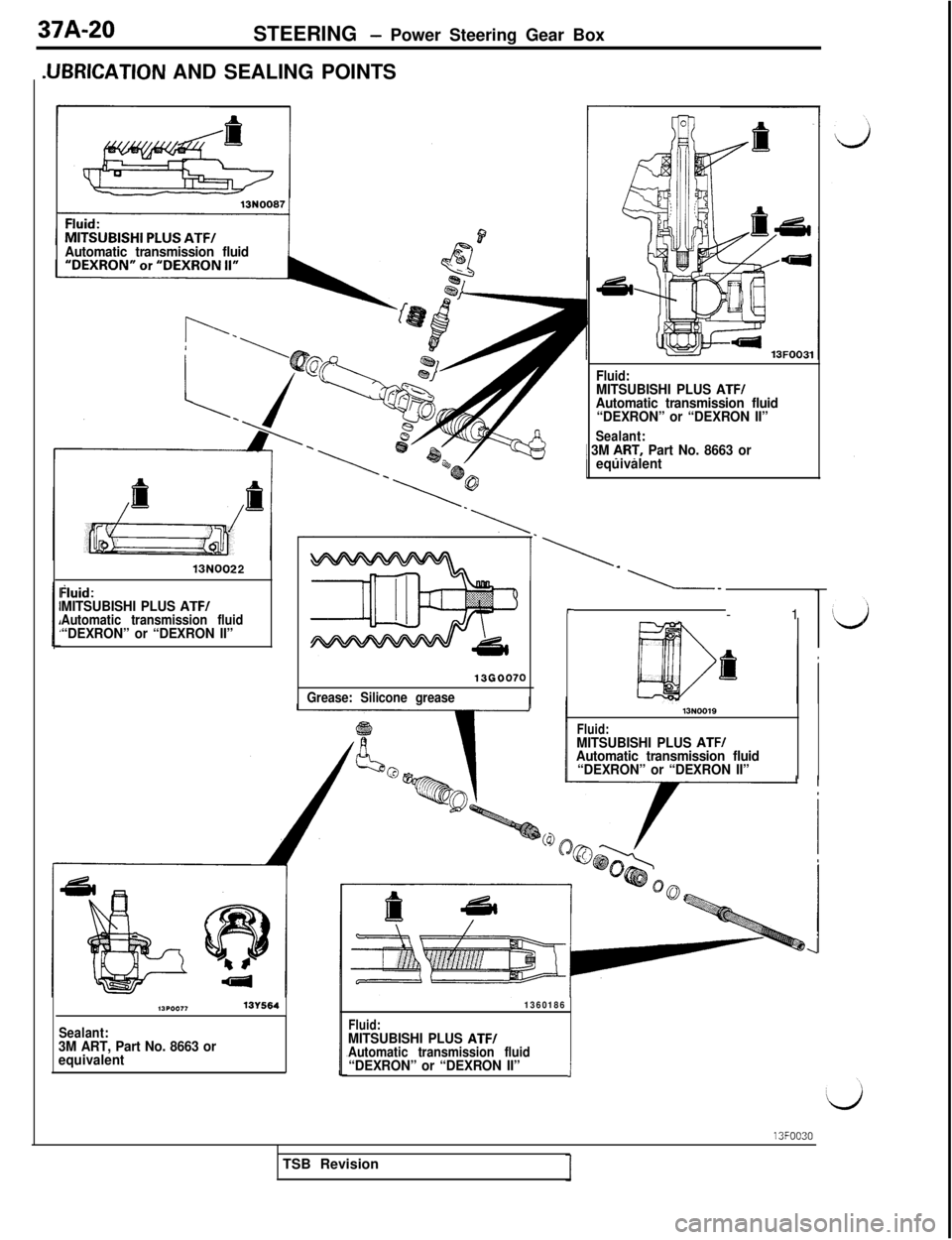
STEERING - Power Steering Gear Box
.UBRICATION AND SEALING POINTS
Automatic transmission fluid
13N0022
hid:MITSUBISHI PLUS ATF/Automatic transmission fluid“DEXRON” or “DEXRON II”
13G0070
Grease: Silicone greaseFluid:
MITSUBISHI PLUS ATF/Automatic transmission fluid
“DEXRON” or “DEXRON II”
Sealant:1 3M ART, Part No. 8663 or
equivalent.
L--1
I-
13N0019
Fluid:MITSUBISHI PLUS ATF/Automatic transmission fluid
“DEXRON” or “DEXRON II”
l.?POO,,13Y564
Sealant:3M ART, Part No. 8663 or
equivalent
1360186
Fluid:MITSUBISHI PLUS ATF/
Automatic transmission fluid
“DEXRON” or “DEXRON II”i13FOO30
TSB Revision
Page 852 of 1146
37A-24
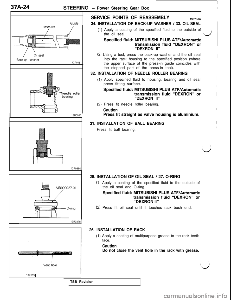
STEERING - Power Steering Gear Box
/Oil seal
Back-up washer13A0181L
GuideNeedle roller
bearmg13R0547
MB990927-01
&
13R0378
Vent hole
SERVICE POINTS OF REASSEMBLYM37PHAW
34. INSTALLATION OF BACK-UP WASHER / 33. OIL SEAL(1) Apply a coating of the specified fluid to the outside of
the oil seal.
LJSpecified fluid: MITSUBISHI PLUS
ATF/Automatictransmission fluid “DEXRON” or
“DEXRON II”
(2) Using a tool, press the back-up washer and the oil seal
into the rack housing to the specified position (whereIthe upper surface of the press-in guide coincides with
the stepped part of the press-in tool).
32. INSTALLATION OF NEEDLE ROLLER BEARINGI(1) Apply specified fluid to housing, bearing and oil seal
Ipress fitting surface.
ISpecified fluid: MITSUBISHI PLUS ATF/Automatictransmission fluid “DEXRON” or
I“DEXRON II”(2) Press fit needle roller bearing.
CautionIPress fit straight as valve housing is aluminium.
31. INSTALLATION OF BALL BEARINGPress fit ball bearing.
28. INSTALLATION OF OIL SEAL
/ 27. O-RING
(1) Apply a coating of the specified fluid to the outside of
the oil seal and O-ring.
Specified fluid: MITSUBISHI PLUS
ATF/Automatictransmission fluid “DEXRON” or
“DEXRON II”
(2) Press fit oil seal until it touches rack bush end.
26. INSTALLATION OF RACK(1) Apply a coating of multipurpose grease to the rack teeth
face.
Caution
Do not close the vent hole in the rack with grease.13K583(
TSB Revision
Page 853 of 1146
STEERING - Power Steering Gear Box37A-25
Back-up washer1360147
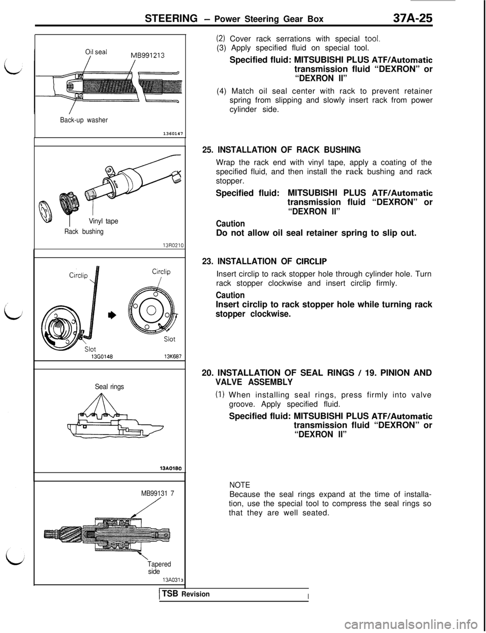
(2) Cover rack serrations with special tool.
(3) Apply specified fluid on special tool.
Specified fluid: MITSUBISHI PLUS
ATFIAutomatictransmission fluid “DEXRON” or
“DEXRON II”(4) Match oil seal center with rack to prevent retainer
spring from slipping and slowly insert rack from power
cylinder side.
Vinyl tape
Rack bushing
136014613K687
Seal rings
MB99131 7
Tapered
side13A0313
25. INSTALLATION OF RACK BUSHINGWrap the rack end with vinyl tape, apply a coating of the
specified fluid, and then install the rack bushing and rack
stopper.
Specified fluid:MITSUBISHI PLUS
ATF/Automatictransmission fluid “DEXRON” or
“DEXRON II”
CautionDo not allow oil seal retainer spring to slip out.
23. INSTALLATION OF CIRCLIPInsert circlip to rack stopper hole through cylinder hole. Turn
rack stopper clockwise and insert circlip firmly.
CautionInsert circlip to rack stopper hole while turning rack
stopper clockwise.20. INSTALLATION OF SEAL RINGS
/ 19. PINION AND
VALVE ASSEMBLY
(I) When installing seal rings, press firmly into valve
groove. Apply specified fluid.
Specified fluid: MITSUBISHI PLUS
ATF/Automatictransmission fluid “DEXRON” or
“DEXRON II”
NOTEBecause the seal rings expand at the time of installa-
tion, use the special tool to compress the seal rings so
that they are well seated.
ITSB RevisionI
Page 856 of 1146
37A-28
STEERING - Power Steering Oil Pump
POWER STEERING OIL PUMP
REMOVAL AND INSTALLATION
I
M37RA-.
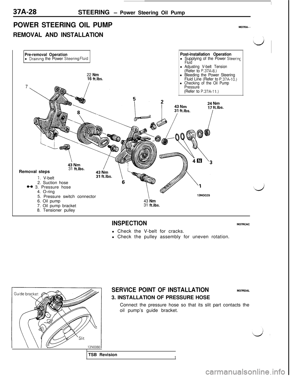
Pre-removal Operationl Draintng the Power Steenng Flurd
22 Nm
16 ft.lbs.
7
Post-installation Operationl Supplying of the Power Steering
Fluid
l Adjusting V-belt Tension(Refer to P.37A-8.)l Bleeding the Power Steering
Fluid Line (Refer to P.37A-10.)l Checking of the Oil Pump
Pressure
(Refer to P.37A-11.)Removal steps
31 ft.lbs.
1. V-belt
2. Suction hose
** 3. Pressure hose
4. O-ring
5. Pressure switch connector
6. Oil pump
7. Oil pump bracket
8. Tensioner pulley
43 Nm31 fklbs.
13N0029
Ij
INSPECTIONM37RCACl Check the V-belt for cracks.
l Check the pulley assembly for uneven rotation.
SERVICE POINT OF INSTALLATIONM37ROAL3. INSTALLATION OF PRESSURE HOSE
Connect the pressure hose so that its slit part contacts the
oil pump’s guide bracket.
TSB Revision
1