relay MITSUBISHI 3000GT 1992 2.G Owner's Manual
[x] Cancel search | Manufacturer: MITSUBISHI, Model Year: 1992, Model line: 3000GT, Model: MITSUBISHI 3000GT 1992 2.GPages: 738, PDF Size: 35.06 MB
Page 49 of 738
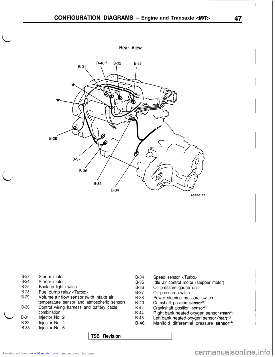
Downloaded from www.Manualslib.com manuals search engine B-23
B-24
B-25
B-28
B-29
B-30
B-31
B-32
B-33
Rear View
B-46*4
B-32
B-33
A36F0167
Starter motor
Starter motor
Back-up light switchFuel pump relay
temperature sensor and atmospheric sensor)
Control wiring harness and battery cable
combination
Injector No. 2
Injector No. 4
Injector No. 6
B-34
B-35
B-36
B-37
B-38
B-40
B-41
B-44
B-45B-46
Speed sensor
Idle air control motor (stepper motor)
Oil pressure gauge unit
Oil pressure switch
Power steering pressure switch
Camshaft position
sensor*2
Crankshaft position sensor*2Right bank heated oxygen sensor
(rear)*3Left bank heated oxygen sensor
(rear)*3Manifold differential pressure
sensor*4
CONFIGURATION DIAGRAMS - Engine and Transaxle
TSB Revision
Page 52 of 738
Downloaded from www.Manualslib.com manuals search engine 50CONFIGURATION DIAGRAMS - Dash Panel
DASH PANEL
Connector
symbol
C
01thru
45
NOTE*I: 1992 models
*2: Up to 1995 models
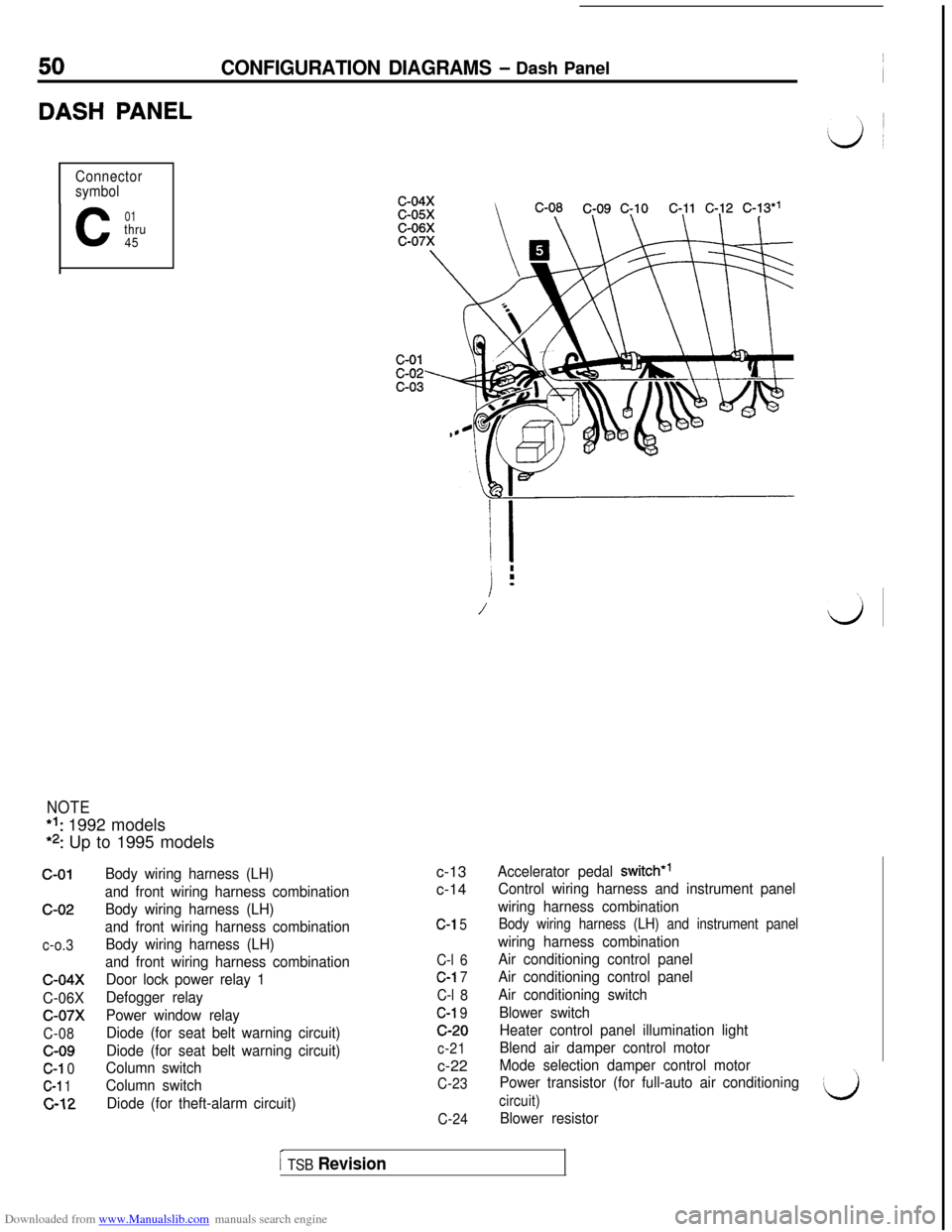
c-01c-02
c-o.3
c-04x
C-06X
c-07x
C-08c-09
C-l 0
C-l 1
c-12
Body wiring harness (LH)
and front wiring harness combination
Body wiring harness (LH)
and front wiring harness combination
Body wiring harness (LH)
and front wiring harness combination
Door lock power relay 1
Defogger relay
Power window relay
Diode (for seat belt warning circuit)
Diode (for seat belt warning circuit)
Column switch
Column switch
Diode (for theft-alarm circuit)c-13
c-14
C-l 5
C-l 6
C-l 7
C-l 8
C-l 9c-20
c-21c-22
C-23
C-24
/ i
i
.m
/\\
LJ
Accelerator pedal switch*’
Control wiring harness and instrument panel
wiring harness combination
Body wiring harness (LH) and instrument panel
wiring harness combination
Air conditioning control panel
Air conditioning control panel
Air conditioning switch
Blower switch
Heater control panel illumination light
Blend air damper control motor
Mode selection damper control motor
Power transistor (for full-auto air conditioning
circuit)
Blower resistor
I TSB Revision
Page 53 of 738
Downloaded from www.Manualslib.com manuals search engine CONFIGURATION DIAGRAMS - Dash Panel51
C-32c-33
A36F0179
00004255
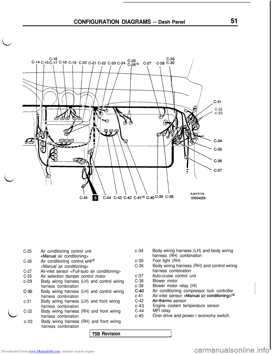
C-25
C-26
C-27
C-28c-29
c-30
c-31
C-32c-33
Air conditioning control unit
Air conditioning control
unit*2
Air-inlet sensor
Air selection damper control motor
Body wiring harness (LH) and control wiring
harness combination
Body wiring harness (LH) and control wiring
harness combination
Body wiring harness (LH) and front wiring
harness combination
Body wiring harness (RH) and front wiring
harness combination
Body wiring harness (RH) and front wiring
harness combinationc-34
c-35
C-36c-37
C-38c-39c-40
c-41
C-42c-43
C-44c-45Body wiring harness (LH) and body wiring
harness (RH) combination
Foot light (RH)Body wiring harness (RH) and control wiring
harness combination
Auto-cruise control unit
Blower motor
Blower motor relay (HI)
Air conditioning compressor lock controllerAir-inlet sensor
Air-therm0 sensor
Engine coolant temperature sensorMFI relay
Over drive and power
/ economy switch
TSB Revision1
Page 54 of 738
Downloaded from www.Manualslib.com manuals search engine 52CONFIGURATION DIAGRAMS - Dash Panel
JUNCTION BLOCK
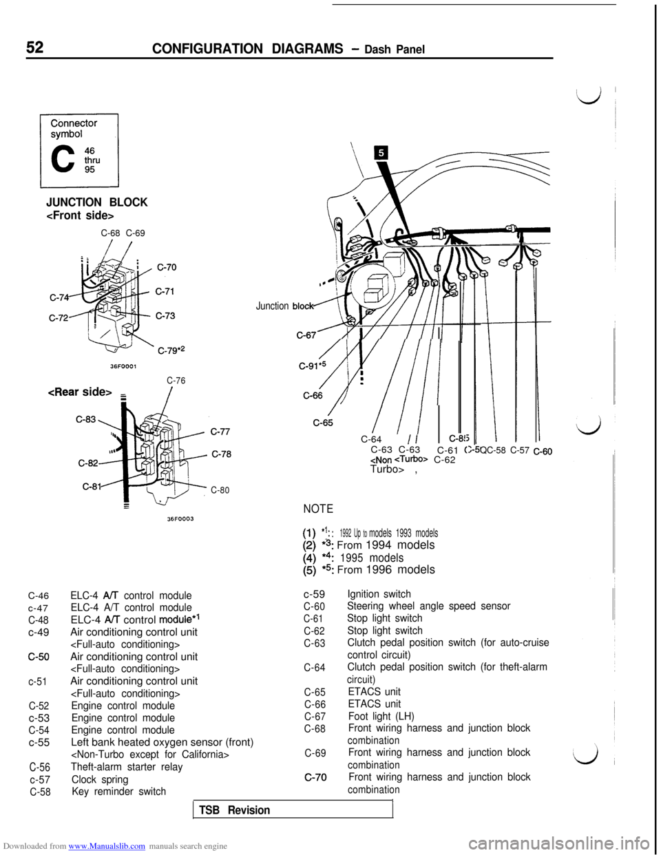
C-68 C-69C-46
c-47
C-48c-49
c-50
c-51
C-52c-53
C-54c-55
C-56
c-57
C-58
36FOOOl
C-76
/
C-80
36FOOO3
Junction
/C-91*5 i
Av///I :-C-64
1 /:-8!C-63 C-63
C-61
(
Turbo> ,
NOTE
[-I!1:: :1992 Up tomodels 1993 models
*s: From 1994 models
*4:1995models
(5)*5: From 1996 models
QC-58 C-57 C-60
ELC-4 AA control module
ELC-4 A/T control moduleELC-4
AiT control module*’Air conditioning control unit
Engine control module
Engine control module
Engine control moduleLeft bank heated oxygen sensor (front)
Theft-alarm starter relay
Clock spring
Key reminder switchc-59
C-60
C-61
C-62
C-63
C-64
C-65
C-66
C-67
C-68
C-69c-70
Ignition switch
Steering wheel angle speed sensor
Stop light switch
Stop light switch
Clutch pedal position switch (for auto-cruise
control circuit)
Clutch pedal position switch (for theft-alarm
circuit)
ETACS unit
ETACS unit
Foot light (LH)
Front wiring harness and junction block
combination
Front wiring harness and junction block
combination
Front wiring harness and junction block
combinationITSB Revision
Page 55 of 738
Downloaded from www.Manualslib.com manuals search engine CONFIGURATION DIAGRAMS - Dash Panel53
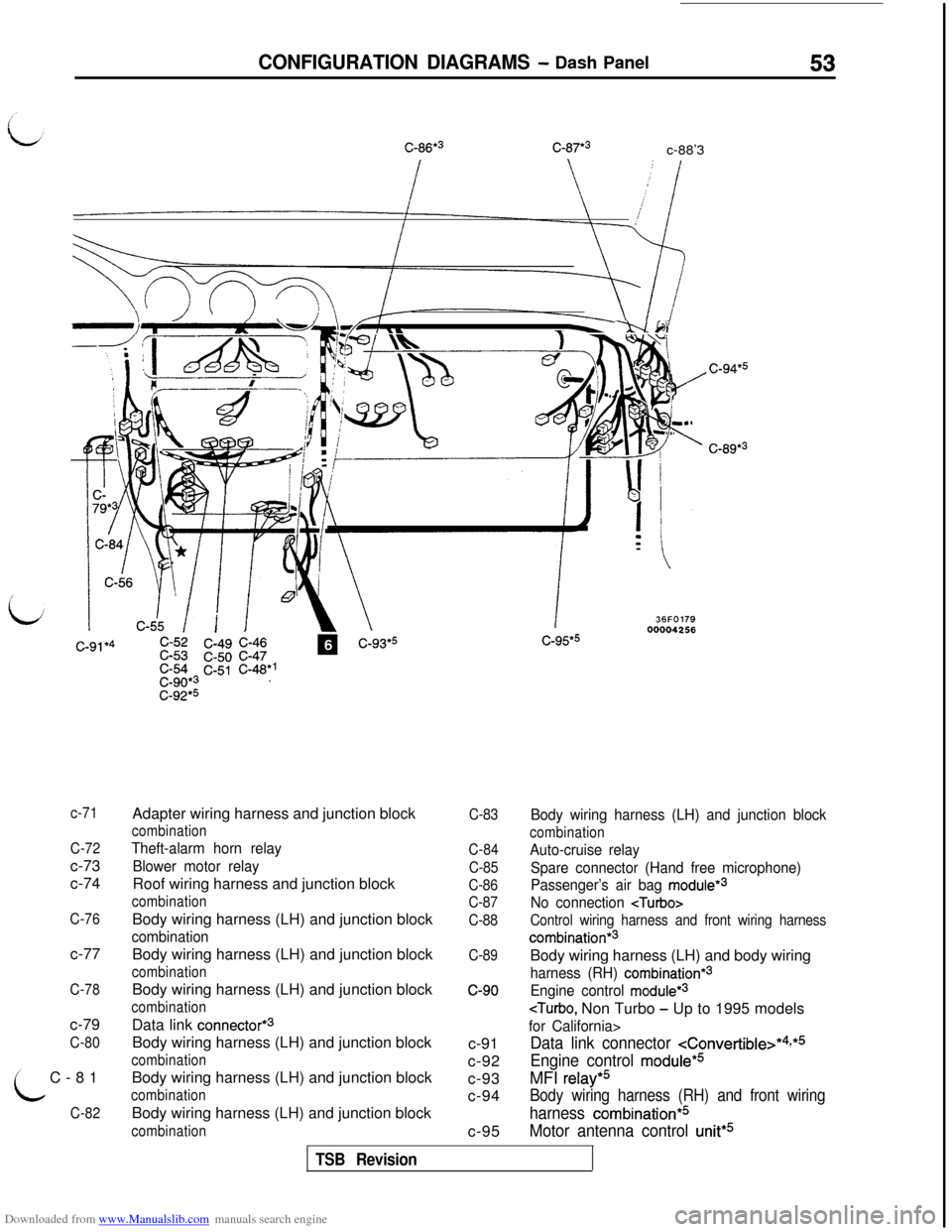
c-86*3C-87*3c-88’3
-J-----1)!_1/t’ \.- -b!w
C-89*3
i
c-71
C-72c-73
c-74
C-76c-77
C-78c-79
C-80C-81
C-82Adapter wiring harness and junction block
combination
Theft-alarm horn relay
Blower motor relayRoof wiring harness and junction block
combinationBody wiring harness (LH) and junction block
combinationBody wiring harness (LH) and junction block
combinationBody wiring harness (LH) and junction block
combinationData link
connector*3Body wiring harness (LH) and junction block
combinationBody wiring harness (LH) and junction block
combinationBody wiring harness (LH) and junction block
combination
36FO17900004256
C-83
C-84
C-85
C-86
C-87
C-88
C-89c-90
c-91
c-92
c-93
c-94
c-95Body wiring harness (LH) and junction block
combination
Auto-cruise relay
Spare connector (Hand free microphone)
Passenger’s air bag
module*3
No connection
Control wiring harness and front wiring harness
combination*3Body wiring harness (LH) and body wiring
harness (RH) combination*3
Engine control module*3
Data link connector
Engine control module*5MFI
relay*5
Body wiring harness (RH) and front wiring
harness combination*5
Motor antenna control unit*5
TSB Revision
Page 58 of 738
Downloaded from www.Manualslib.com manuals search engine 56CONFIGURATION DIAGRAMS - Interior
INTERIOR
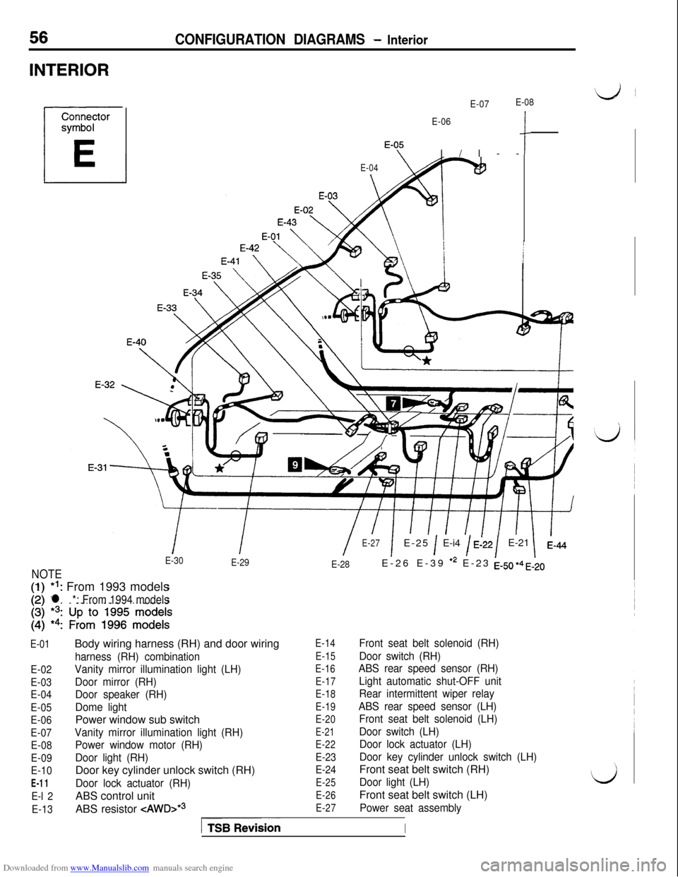
E-07E-08
E-06
‘-OfI/l--c
E-04
\
II/E-27
E-30
1E-25 1 E-i4 / E:22/E-21 1
E-29
E-28
NOTEE-26 E-39
*2 E-23 EJJ, +4 ,520*I: From 1993 models
l *: From 1994 models
E-01
E-02
E-03
E-04
E-05
E-06
E-07
E-08
E-09
E-10
E-11
E-l 2
E-13Body wiring harness (RH) and door wiring
harness (RH) combination
Vanity mirror illumination light (LH)
Door mirror (RH)
Door speaker (RH)
Dome lightPower window sub switch
Vanity mirror illumination light (RH)
Power window motor (RH)
Door light (RH)Door key cylinder unlock switch (RH)
Door lock actuator (RH)ABS control unit
ABS resistor
-=zAWD>*~
E-14
E-15
E-16
E-17
E-18
E-19
E-20
E-21
E-22
E-23
E-24
E-25
E-26
E-27
Front seat belt solenoid (RH)
Door switch (RH)
ABS rear speed sensor (RH)
Light automatic shut-OFF unit
Rear intermittent wiper relay
ABS rear speed sensor (LH)
Front seat belt solenoid (LH)
Door switch (LH)
Door lock actuator (LH)
Door key cylinder unlock switch (LH)Front seat belt switch (RH)
Door light (LH)Front seat belt switch (LH)
Power seat assembly
ITSBionI
Page 59 of 738
Downloaded from www.Manualslib.com manuals search engine CONFIGURATION DIAGRAMS - InteriorE-45 E-46 E-47
E-48E-4g
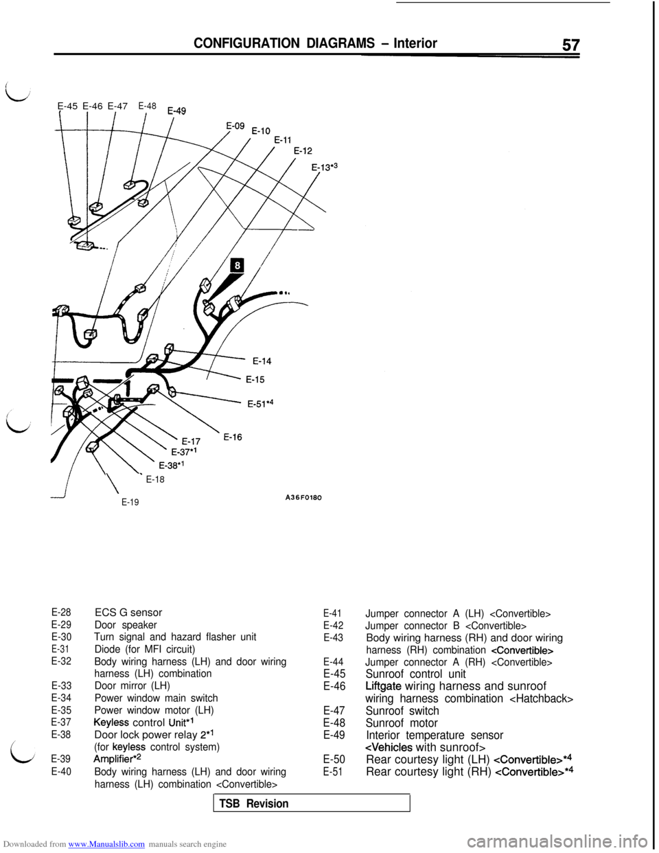
E-28
E-29
E-30
E-31
E-32
E-33
E-34
E-35
E-37
E-38
E-39
E-40
\
’ E-18
E-19ECS G sensor
Door speaker
Turn signal and hazard flasher unit
Diode (for MFI circuit)
Body wiring harness (LH) and door wiring
harness (LH) combination
Door mirror (LH)
Power window main switch
Power window motor (LH)
Keyless control Unit”’Door lock power relay 2*’
(for keyless control system)
Amplifier*2
Body wiring harness (LH) and door wiring
harness (LH) combination
E-41
E-42
E-43
E-44
E-45
E-46
E-47
E-48
E-49
E-50
E-51
Jumper connector A (LH)
Jumper connector B
harness (RH) combination
Jumper connector A (RH)
Sunroof control unit
Liftgate wiring harness and sunroof
wiring harness combination
Sunroof switch
Sunroof motor
Interior temperature sensor
Rear courtesy light (LH)
cConvertible>*4Rear courtesy light (RH)
cConvertible>*4
TSB Revision
Page 69 of 738
Downloaded from www.Manualslib.com manuals search engine CIRCUIT DIAGRAMS - Power Distribution Circuit67
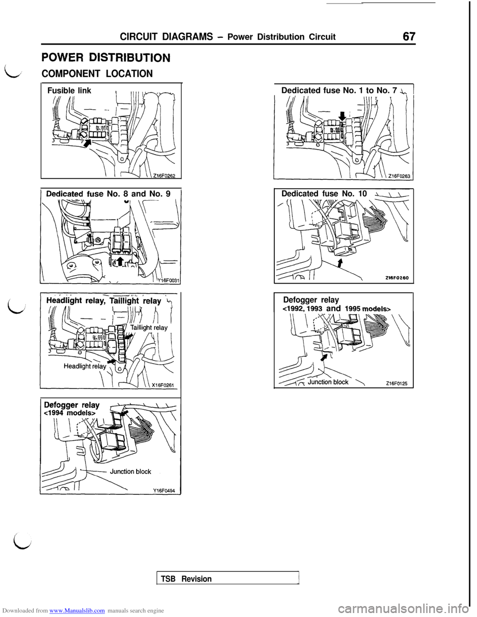
POWER DISTRIBUTION
L,’COMPONENT LOCATION
Fusible linkse No. 8 and No. 9Dedicated fuse No. 1 to No. 7 A.,1
~~ ~Dedicated fuse No. 10LJJ-
Z16FO280
Defogger relay
4992, 1993 and 1995 models>
TSB Revision
Page 70 of 738
Downloaded from www.Manualslib.com manuals search engine 68CIRCUIT DIAGRAMS - Power Distribution Circuit
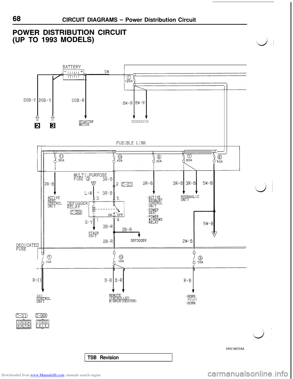
POWER DISTRIBUTION CIRCUIT
(UP TO 1993 MODELS)
BATTERY
Y 2QB-Y20B-R8W-R BW-R
nA111
n ni;+!$;ERGENERATOR
FUSIBLE LINK
I
L
R-i
!R-B
I
MULTI-PURPOSEFUSE @3R-BD
YL-R- 3R-B00
@@40A
30A26?OA
0IOA10A
B-R B-RR-B
1 11ABS;C$ROL.HORNRELAY.HORNHROlMOOAA
TSB Revision
Page 71 of 738
Downloaded from www.Manualslib.com manuals search engine CIRCUIT DIAGRAMS - Power Distribution Circuit69
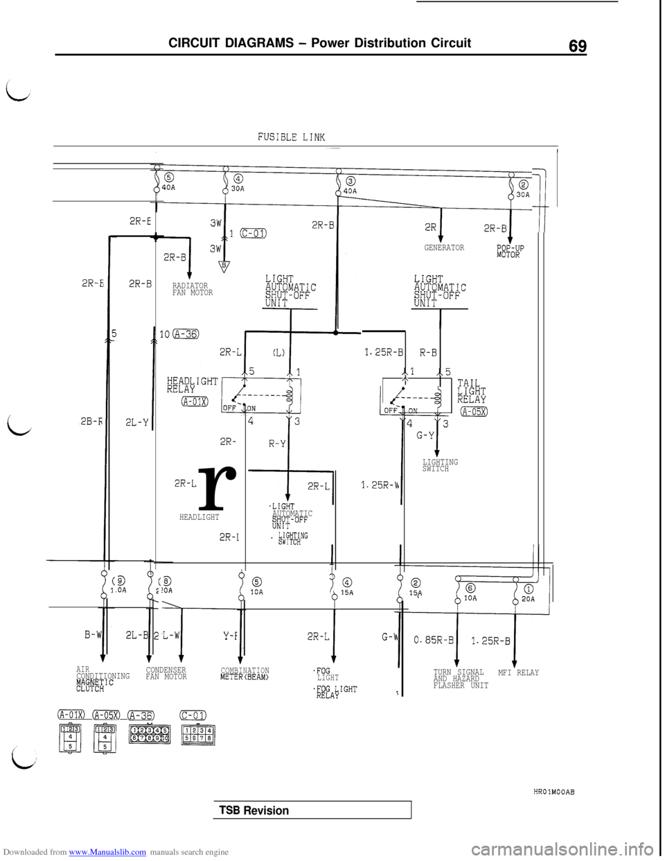
FUSIBLE LINK
/
i
2R-E
2B-r;
c9
.OAB!OA0,10A015A
B-W'L-W
T
Y-F2R-L
i
G-k2L-B
2R-E
2R-BRADIATOR
FAN MOTOR
2R-
2R-Lr
HEADLIGHT
2R-I
.LIGHTAUTOMATIC;#JT-OFF
. #;HNG
1;
1.25R-Cc
GENERATORE&RUP
LIGHTAUTOMATIC&#~+-oFF
I
1.25R-BR-B
..l,.5ATAILLIGHTRELAY
(A-05X)
LIGHTING
SWITCH
AIRCONDITIONINGCONDENSER#~T"~~ICFAN MOTOR
COMBINATIONMETERCBEAM).FOGLIGHT
$"fALyIGHTr
IA-01x) (A-05X) @iqJ(c-01)
015A
TURN SIGNAL
AND HAZARDMFI RELAY
FLASHER UNITHROlMOOAB
TSB Revision