MITSUBISHI 3000GT 1992 2.G Workshop Manual
3000GT 1992 2.G
MITSUBISHI
MITSUBISHI
https://www.carmanualsonline.info/img/19/7561/w960_7561-0.png
MITSUBISHI 3000GT 1992 2.G Workshop Manual
Trending: key battery, ABS, oil type, air suspension, keyless, tow, ignition
Page 551 of 738
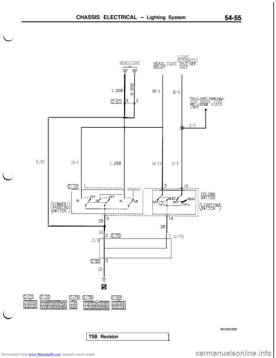
Downloaded from www.Manualslib.com manuals search engine CHASSIS ELECTRICAL - Lighting System54-55
LIGHT
AUTOMATIC
IGHT s/Y;-OFFHEADLIGHTHE!REL\DL,AY
1.25RG-Y
G-Y
TAILLIGHT,PARKING/
SIDE MARKER LIGHT
;yeHkICENSE PLATE
JG-Y
10
t
0.85(R-Y
(c-10)1
1.25R(R-Y
-----__
r
)2---------------
~:JqzT
-----_
-_
ILO
OP
2Bx.3 (c-76)
J/B A,\ 7 (c-78)
(c-82) "5
2B
HROBM03BB
TSB Revision1
Page 552 of 738
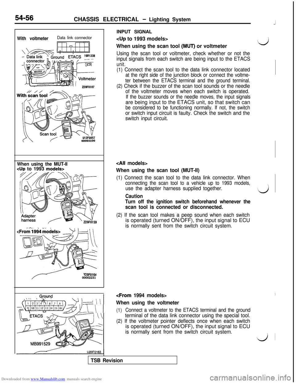
Downloaded from www.Manualslib.com manuals search engine INPUT SIGNALWith voltmeterData link connector
Ii ri7-11
When using the scan tool (MUT) or voltmeter‘d
Using the scan tool or voltmeter, check whether or not the
input signals from each switch are being input to the ETACS
unit.
54-56CHASSIS ELECTRICAL - Lighting System
(1) Connect the scan tool to the data link connector located
at the right side of the junction block or connect the voltme-
ter between the ETACS terminal and the ground terminal.
(2) Check if the buzzer of the scan tool sounds or the needle
of the voltmeter moves when each switch is operated.
If the buzzer sounds or the needle moves, the input signalsare being input to the ETACS unit, so that switch can
be considered to be functioning normally. If not, the switch
or switch input circuit is faulty. Check the switch and the
switch input circuit.
When using the MUT-II
CUP to 1993 models>
Y2OFO16400002231,
0,@y.m$
( 1 1 1 2 1; 1 4% 16 1 7 1 8 / 1
’ 1-d \ \ 1
~~~4i10illi12i13illi15i16v~~~1 \ \ 1U2OFO163
When using the scan tool (MUT-II)
(1) Connect the scan tool to the data link connector. When
connecting the scan tool to a vehicle up to 1993 models,
use the adapter harness supplied together.‘dCaution
Turn off the ignition switch beforehand whenever the
scan tool is connected or disconnected.
(2) If the scan tool makes a peep sound when each switchis operated (turned ON/OFF), the input signal to ECU
is normally sent from the switch circuit system.
I
When using the voltmeter
(1)Connect a voltmeter to the ETACS terminal and the ground
terminal of the data link connector using the special tool.
(2) If the voltmeter pointer deflects once when each switchis operated (turned ON/OFF), the input signal to ECU
is normally sent from the switch circuit system.
do
TSB Revision
Page 553 of 738
Downloaded from www.Manualslib.com manuals search engine 54957
NOTES
TSB
Revision
Page 554 of 738
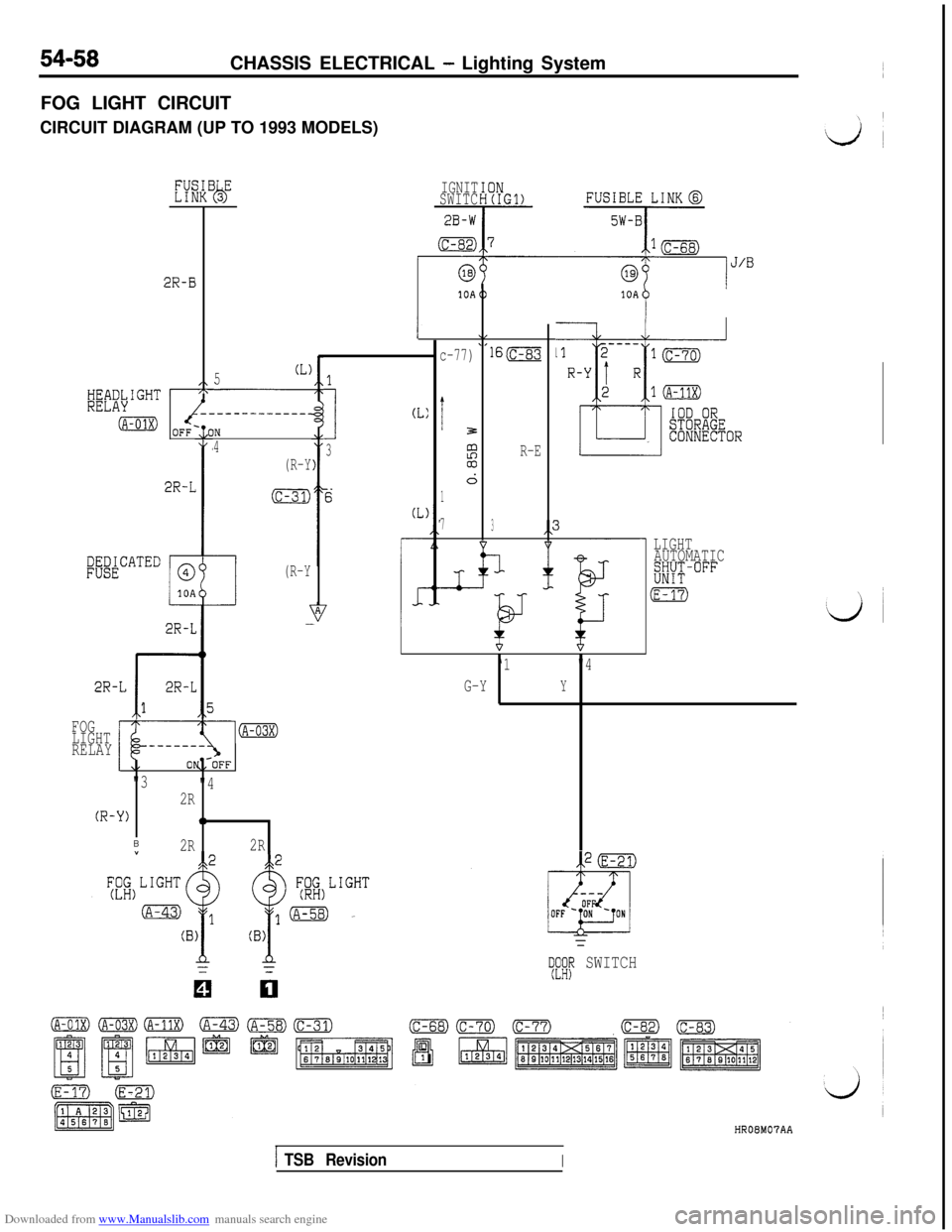
Downloaded from www.Manualslib.com manuals search engine 54-58CHASSIS ELECTRICAL - Lighting System
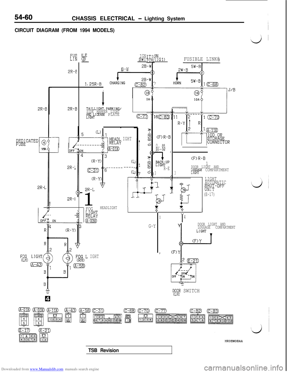
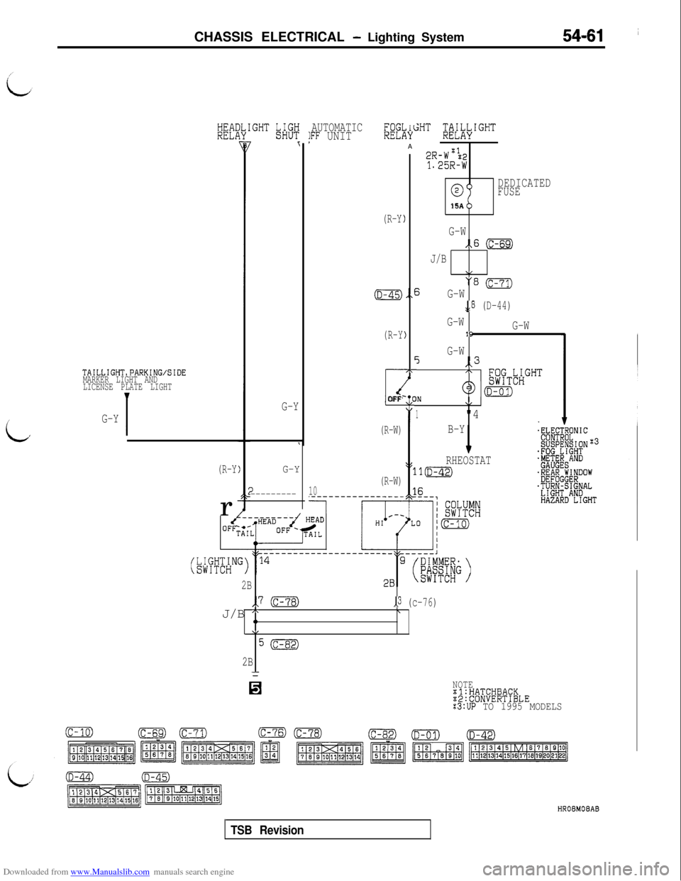
FOG LIGHT CIRCUIT
CIRCUIT DIAGRAM (UP TO 1993 MODELS)
2R-B
,\
-------------_
OFF-10IN
4
(R-Y
(c-31)2R-L
PWATED
c
@
10A
(R-Y
2R-L
2R-L
r
2R-L
1
5(L)
FOG
LIGHT
RELAY
(R-
"3
"4
2R
-Y)0
B2R2RIGNIT
SWITC
2B-W
(c-82)
1
I
CL:
3
c-77)
i3
%03
d
1
7lS(c-83
R-E
3
-L
10A
P
- LIGHT
AUTOMATIC
w-°FF
(E-
‘1"4
G-Y
Y
TeKIp SWITCHHROEM07AA
ITSB RevisionI
Page 555 of 738
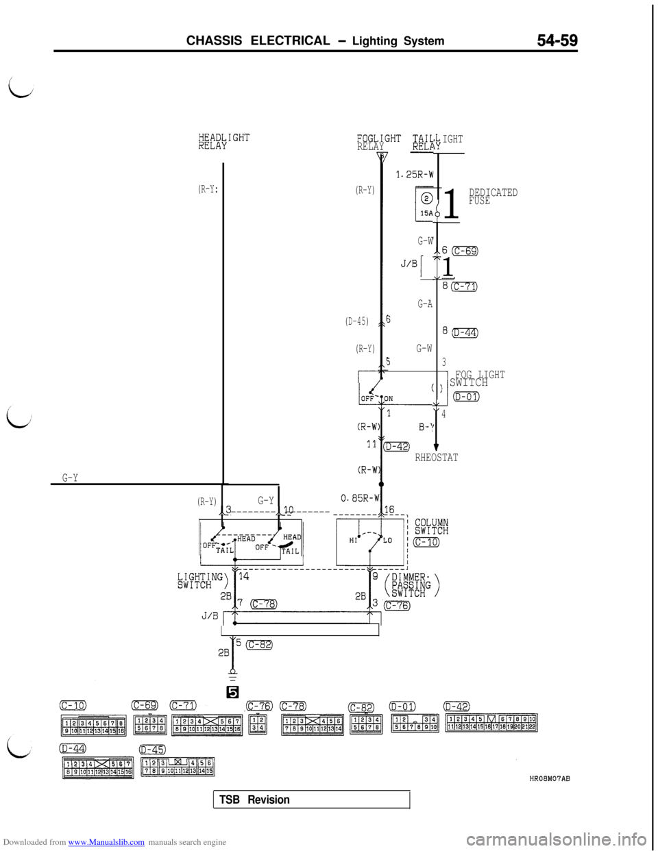
Downloaded from www.Manualslib.com manuals search engine CHASSIS ELECTRICAL - Lighting System54-59
~~if\IGHTFOGLIGHT ;N;RELAYIGHT
(R-Y)
(D-45)
(R-Y)
r-
1.25R-W
1
DEDICATEDFUSE
(R-Y:
G-Y
I
Ib
I
G-W60
1
G-A
5
G-W
53I
FOG LIGHT) SWITCH
(D-al)
I
I
4
RHEOSTAT
(R-Y)G-Y,,3,JO
-------- --------
(c-82)
TSB Revision
Page 556 of 738
Downloaded from www.Manualslib.com manuals search engine 54-60CHASSIS ELECTRICAL - Lighting System
CIRCUIT DIAGRAM (FROM 1994 MODELS)I
2R-E
LEb-
1.25R-B
I
IGNSWI’IN(IGl)FUSIBLE LINK@
7
B-W
2R-B
I I
lr-
TAILLIGHT,PARKING/
SIDE MARKER LIGHT
#eH;ICENSE PLATE
2R-I
(c-7’i
(F>R-B
0. 05B-W (
'7
E%~TUPR-E
3
1
;ig&CATED @
c15
IGHT
2R-1
(F>R-B
1DOOR LIGHT AND
3E'I'UX&GE COMPARTMENT
2R-L1
(L----.
(L
r
1
LIGHT
AUTOMATIC
EK°FF
(E-17)
2R-
i
G-Y
2R-1
FOGHEADLIGHT
kB%
(A-03X)
+J
1I4Y
DOOR LIGHT AND
LUGGAGE COMPARTMENT
I(F>Y
vii L1GHT(A-43)
IGHT
=
TF;fi SWITCHHROBMOBAA
TSB Revision
Page 557 of 738
Downloaded from www.Manualslib.com manuals search engine CHASSIS ELECTRICAL - Lighting System54-61 ~
i,
HEAIRELi
TAILLIGHT,PARKING/SIDE
MARKER LIGHT AND
LICENSE PLATE LIGHT
G-Y
I
(R-Yr
G-Y
\
G-Y
3---------
AUTOMATIC/FF UNIT
10
KEI
(R-Y
(R-Y
c4OFF‘
(R-W)
(R-W)
;HT 'T;TikIGHT
2R-W'&1.25R-W
,lCIYA
)
,,f)
c
7r
/
0%DEDICATED
FUSE15A
G-W
1x6 (c-69)
J/B
\/
5'3 (c-71)G-W
,,a (D-44)
G-W
G-W19
G-W5,,3
" g;FTbHGHT
9IN@cD-ol,\/
1"4
I
B-Y
IRHEOSTAT
11m
_ .
5L
c
2B
,y (c-78),,3 (c-76)
J/B A\0\/
50
2B
Q0NOTE:l:HATCHBACK:2:CONVERTIBLE:3:UP TO 1995 MODELS
TSB RevisionHRO6MO8AB
Page 558 of 738
Downloaded from www.Manualslib.com manuals search engine 54-62CHASSIS ELECTRICAL - Lighting System
OPERATION
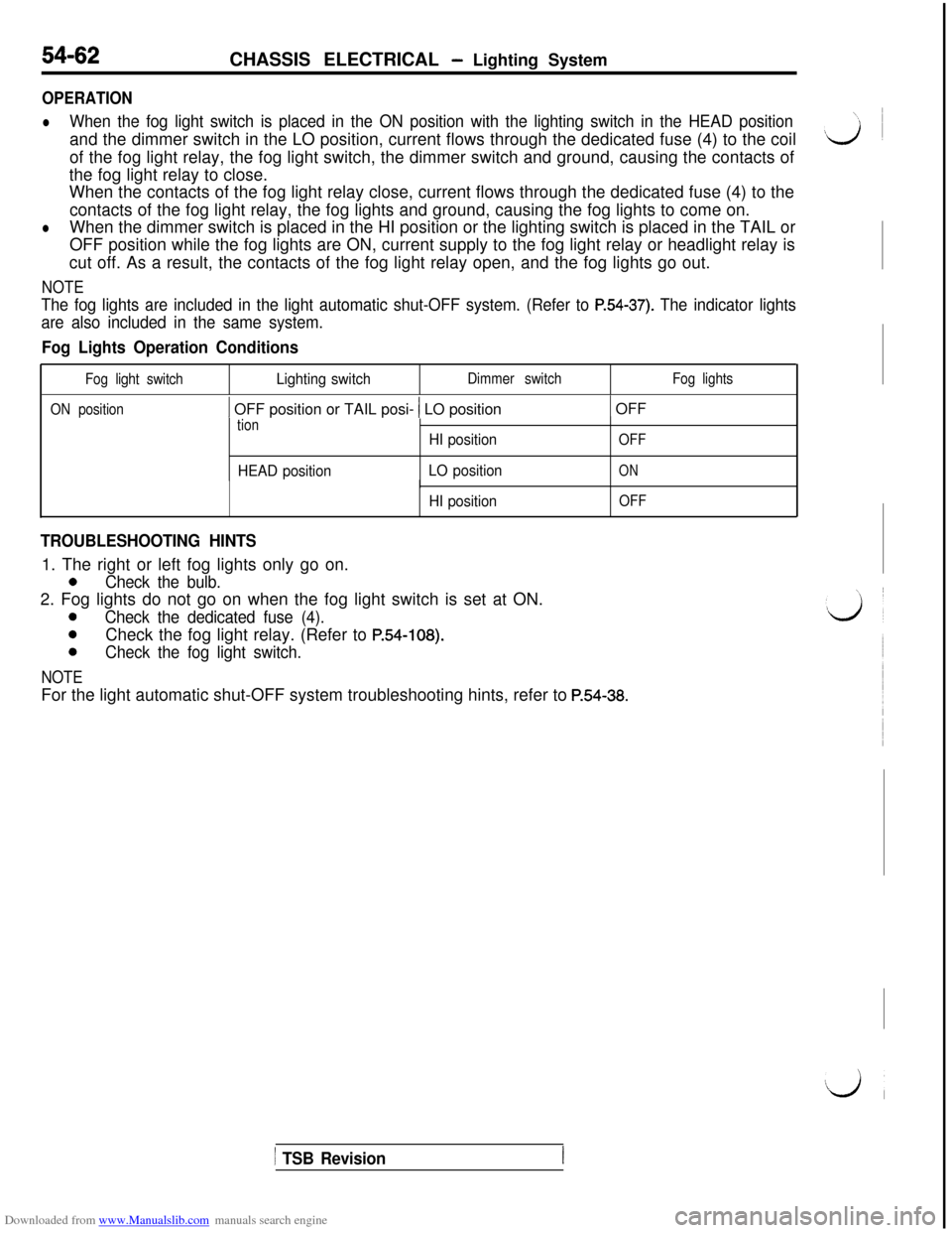
lWhen the fog light switch is placed in the ON position with the lighting switch in the HEAD positionand the dimmer switch in the LO position, current flows through the dedicated fuse (4) to the coil
of the fog light relay, the fog light switch, the dimmer switch and ground, causing the contacts of
the fog light relay to close.
When the contacts of the fog light relay close, current flows through the dedicated fuse (4) to the
contacts of the fog light relay, the fog lights and ground, causing the fog lights to come on.
lWhen the dimmer switch is placed in the HI position or the lighting switch is placed in the TAIL or
OFF position while the fog lights are ON, current supply to the fog light relay or headlight relay is
cut off. As a result, the contacts of the fog light relay open, and the fog lights go out.
NOTE
The fog lights are included in the light automatic shut-OFF system. (Refer to P.54-37). The indicator lights
are also included in the same system.
Fog Lights Operation Conditions
Fog light switchLighting switchDimmer switchFog lights
ON position
1 OFF position or TAIL posi- 1 LO position1 OFF
tion
HEAD positionHI position
LO position
OFF
ON
HI position
I
OFF
TROUBLESHOOTING HINTS1. The right or left fog lights only go on.
0Check the bulb.2. Fog lights do not go on when the fog light switch is set at ON.
0Check the dedicated fuse (4).
0Check the fog light relay. (Refer to P.54-108).
0Check the fog light switch.
NOTEFor the light automatic shut-OFF system troubleshooting hints, refer to
P.54-38.
1 TSB Revision
Page 559 of 738
Downloaded from www.Manualslib.com manuals search engine CHASSIS ELECTRICAL - Lighting System
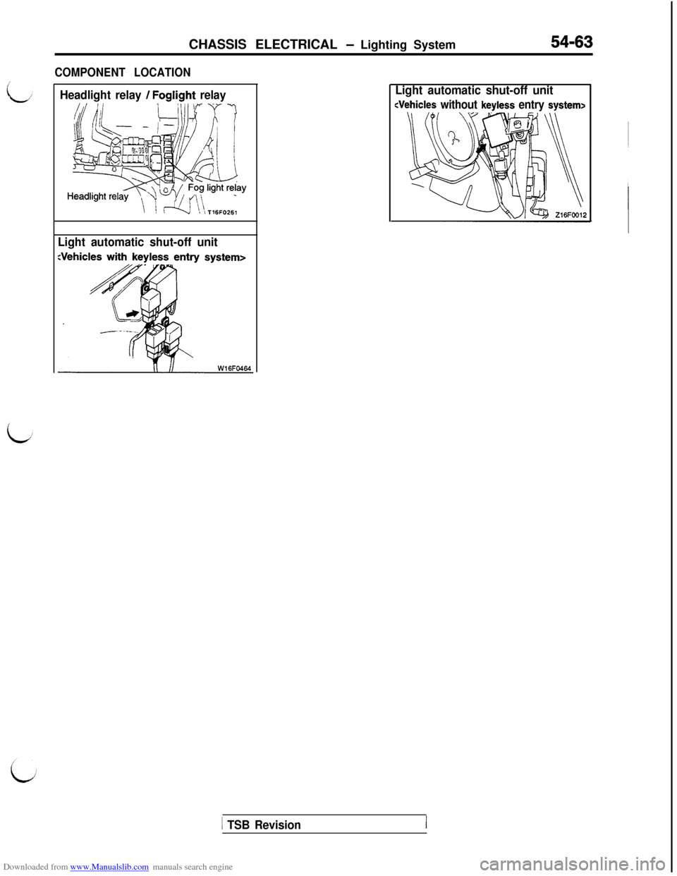
COMPONENT LOCATION
54-63
Headlight relay / Foglight relay
Light automatic shut-off unitLight automatic shut-off unit
1 TSB Revision
Page 560 of 738
Downloaded from www.Manualslib.com manuals search engine 54-64CHASSIS ELECTRICAL - Lighting System
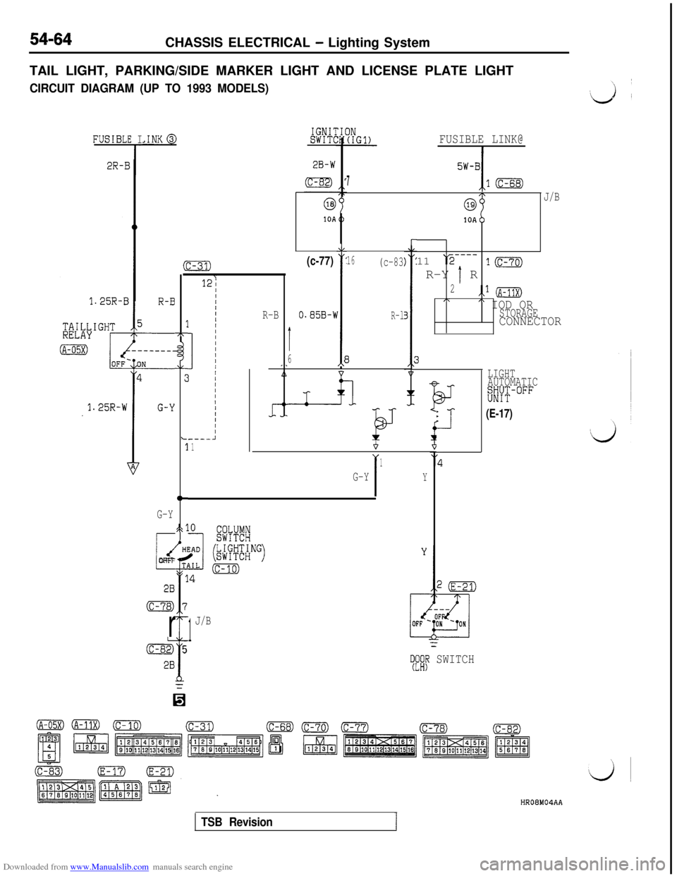
TAIL LIGHT, PARKING/SIDE MARKER LIGHT AND LICENSE PLATE LIGHT
CIRCUIT DIAGRAM (UP TO 1993 MODELS)
IGNIlSWIT(.INK@,E I
T
FUSIBLE LINK@
I
FUSIBL
2R-15W-BI
710
J/B
1OAb11
‘r2---_R-Y
1 R
1m
2.,* (A-11X),\" IOD ORSTORAGECONNECTOR
r
16(c-83(c-77)
1
O.S5B-1I
6E
A
kJ
R-l
3
fi
17r
AL
:c
3
tt-
523
Gi
T1
1
7
f
5
0
G-Y
i
dOFF
28
(c-78)
r
&
28
:-31)
12;
IIIIIIIIIIIIIIIIIII/IIII----A1
R-B
LIGHT
AUTOMATIC
%YT-°FF
I-
BJ-
*
i-l-.(E-17)
I
1
G-YY
1
J/B
=
TFi# SWITCH
HR08M04AA
TSB Revision1
Trending: charging, turn signal bulb, warning, spark plugs, coolant temperature, flat tire, lug pattern
