MITSUBISHI 3000GT 1992 2.G Workshop Manual
Manufacturer: MITSUBISHI, Model Year: 1992, Model line: 3000GT, Model: MITSUBISHI 3000GT 1992 2.GPages: 738, PDF Size: 35.06 MB
Page 511 of 738
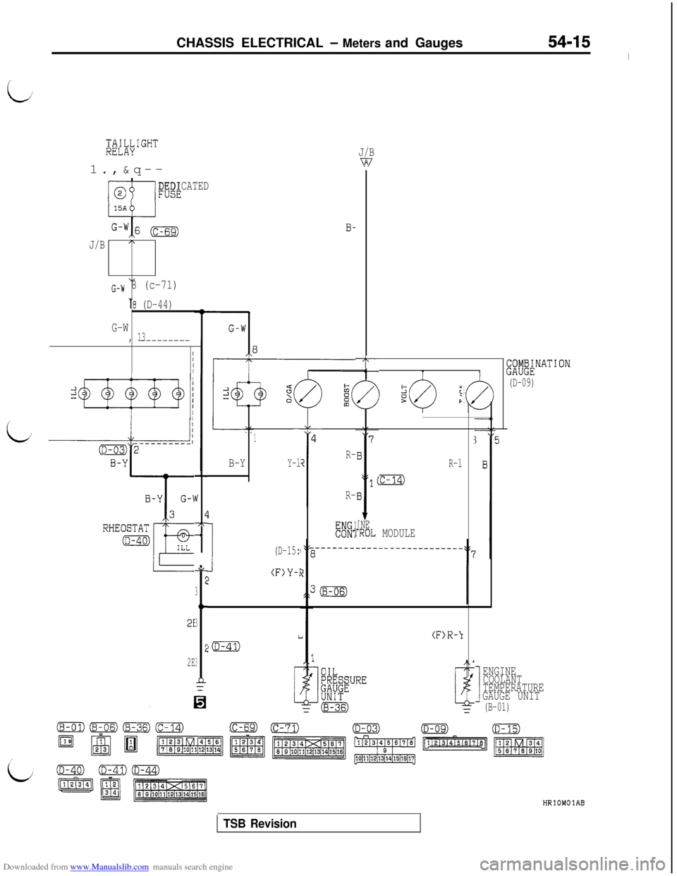
Downloaded from www.Manualslib.com manuals search engine CHASSIS ELECTRICAL - Meters and Gauges54-15
I
;;Tli,;IGHT1.,&q--J/Bv7
w/FUSEDEDICATED
B-
J/BA
\IG-W 8 (c-71)
‘8 (D-44)
G-W, 13---------
II/I-T(Z~Z~~NATION
(D-09)TI1,//II
T
/I
1
Y-l
t:2
f
/
I
1
i
I
R-
R-
t;
’ 052/5F
B-Y
i/
[NErROL
(D-15:
(F)Y-I
R-l
:c-14)J,
!/
L-7r-1
AL
2
3
tc
3
2
3
11
MODULE
2E
(F)R-\I
2E
I
ENGINE
COOLANT
TEMPERATURE
GAUGE UNIT
(B-01)
(c-69)
HRlOMOlAB
TSB Revision
Page 512 of 738
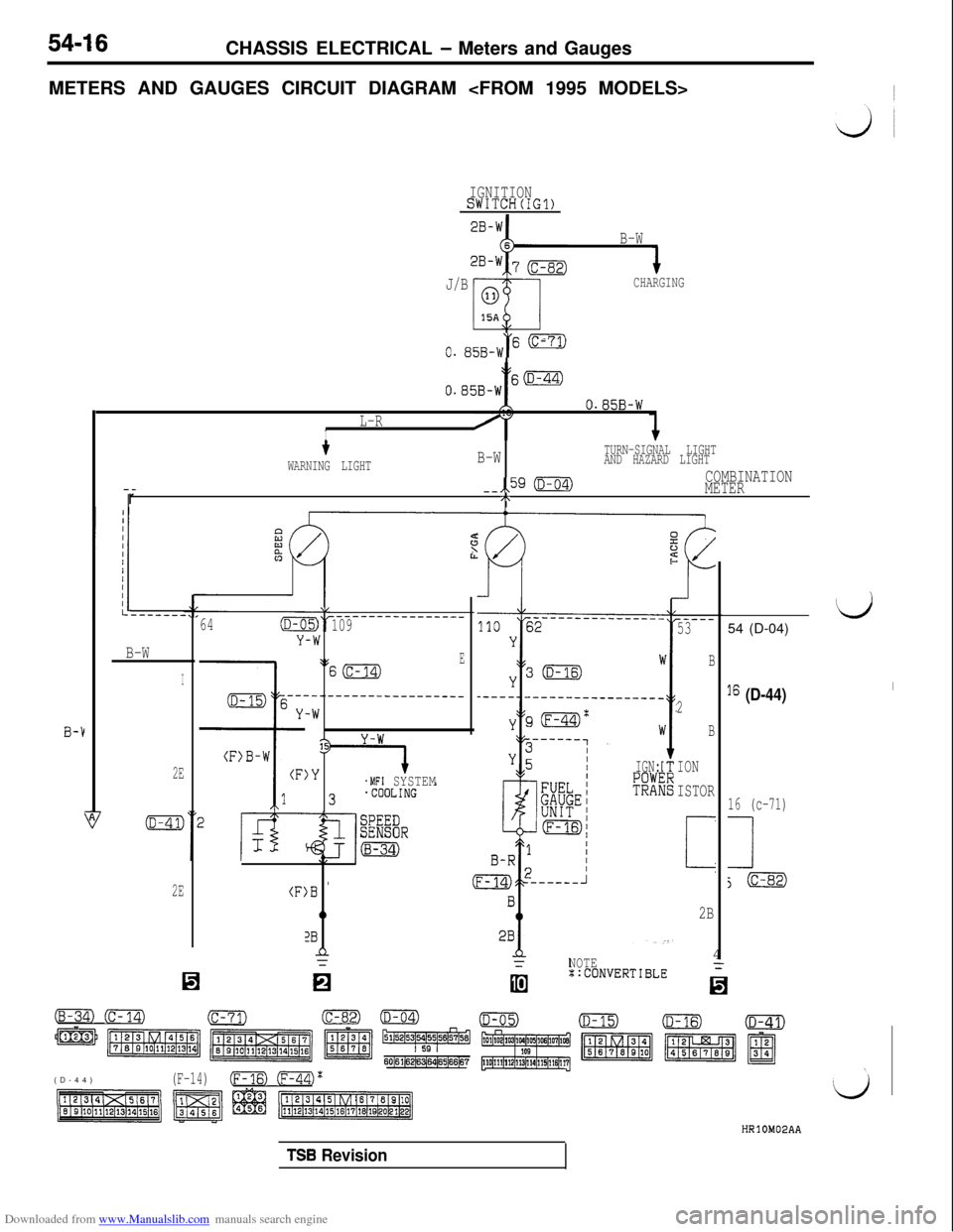
Downloaded from www.Manualslib.com manuals search engine 54-16CHASSIS ELECTRICAL - Meters and Gauges
METERS AND GAUGES CIRCUIT DIAGRAM
IGNITIONSWITCH(IG1)
B-W
J/B
CHARGING
\,
0. 85B-W“' -
tO.B5B-Ws(D-44)
B-1
O.B5B-W
L-RI
--r
tB-WTURN-SIGNAL LIGHT
WARNING LIGHTAND HAZARD LIGHT
--,,59 (D-04)COMBINATION
METER
/\
B-W
I
2E
2E(F:
64(D-C
Y
\L
-W
\:
---.
-W
13
)Y
)B '
0
2Bn=
-------------____109
ES(c-14)
--------------___
.MFI SYSTEMIGN:
R3
(B-34) (c-14)(c-71)
m m m z ~~~~5&4
60161(6216~64165166167(D-44)
(F-14)(Fm (ml'
NOTE4::CONVERTIBLE
-..I
-----53
B
2
B
ION
ISTOR
i
2B
‘d54 (D-04)
I6 (D-44)I
16 (c-71)
1
j(c-82)
TSB Revision
Page 513 of 738
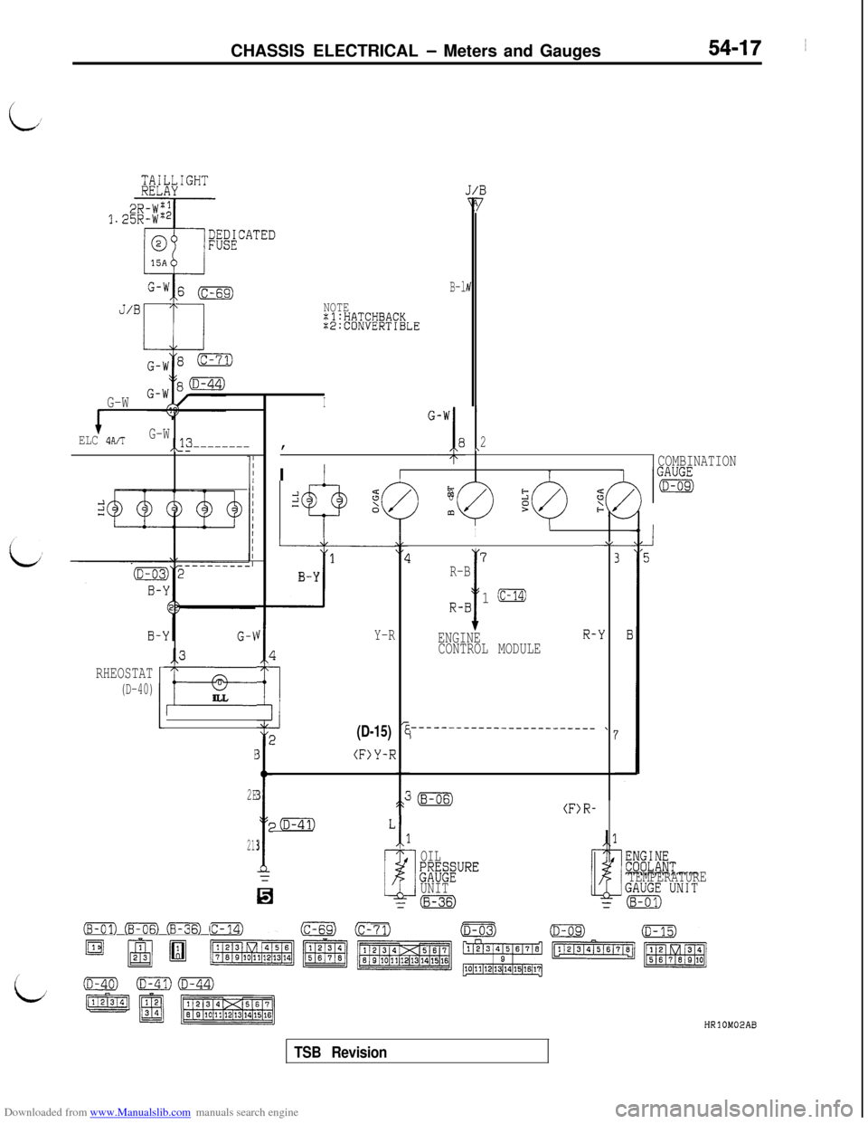
Downloaded from www.Manualslib.com manuals search engine CHASSIS ELECTRICAL - Meters and Gauges54-17 ~
B-lIv
NOTEZl:HATCHBACK:E:CONVERTIBLE
ELC
4A/TG-W,,13---------, '-'I8I2I
I
COMBINATION
I
z
8t;
m?
II
2LY-l,
1
Ii--
L7‘5
B-YR-B
T
R-B
2,Y-RI
1 (C-14)
ENGINER--Y
3
if=
LCONTROL MODULE
RHEOSTAT
(D-40)ILL
:(D-15)
E3
T
(F>Y-R
3
20L
3
r=/
i
2E
21
G-WI
,2_____------_-------_-~~~~I'r
1
c
1
k
OIL
tzi&PREUNITZ(8-36)
(F>R-
TEMPERATURE
(B-01) mm Em cm)(c-69)-(D-03)
D @JB ~,~I:::.:aa-J~~~l
(D-40)(D-41)(m)
=qJ p$EgqHRlOM02AB
TSB Revision
Page 514 of 738
Downloaded from www.Manualslib.com manuals search engine 54-18CHASSIS ELECTRICAL - Meters and Gauges
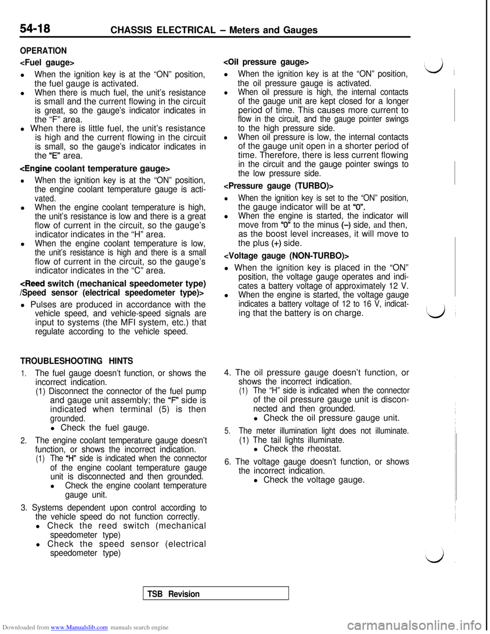
OPERATION
When the ignition key is at the “ON” position,the fuel gauge is activated.
l
When there is much fuel, the unit’s resistanceis small and the current flowing in the circuit
is great, so the gauge’s indicator indicates inthe “F” area.
l When there is little fuel, the unit’s resistance
is high and the current flowing in the circuit
is small, so the gauge’s indicator indicates inthe
“E” area.
lWhen the ignition key is at the “ON” position,
the engine coolant temperature gauge is acti-
vated.l
When the engine coolant temperature is high,
the unit’s resistance is low and there is a greatflow of current in the circuit, so the gauge’s
indicator indicates in the “H” area.
l
When the engine coolant temperature is low,
the unit’s resistance is high and there is a smallflow of current in the circuit, so the gauge’s
indicator indicates in the “C” area.
vehicle speed, and vehicle-speed signals areinput to systems (the MFI system, etc.) that
regulate according to the vehicle speed.
TROUBLESHOOTING HINTS
1.The fuel gauge doesn’t function, or shows the
incorrect indication.
(1) Disconnect the connector of the fuel pumpand gauge unit assembly; the ‘F” side is
indicated when terminal (5) is then
grounded.l Check the fuel gauge.
2.The engine coolant temperature gauge doesn’t
function, or shows the incorrect indication.
(1)The “l-l” side is indicated when the connector
of the engine coolant temperature gauge
unit is disconnected and then grounded.l
Check the engine coolant temperature
gauge unit.
3. Systems dependent upon control according to
the vehicle speed do not function correctly.l Check the reed switch (mechanical
speedometer type)l Check the speed sensor (electrical
speedometer type)
coil pressure gauge>l
When the ignition key is at the “ON” position,
the oil pressure gauge is activated.
lWhen oil pressure is high, the internal contacts
of the gauge unit are kept closed for a longerperiod of time. This causes more current to
flow in the circuit, and the gauge pointer swings
to the high pressure side.
lWhen oil pressure is low, the internal contactsof the gauge unit open in a shorter period of
time. Therefore, there is less current flowing
in the circuit and the gauge pointer swings to
the low pressure side.
lWhen the ignition key is set to the “ON” position,the gauge indicator will be at
“0”.l
When the engine is started, the indicator will
move from
“0” to the minus (-) side, and then,as the boost level increases, it will move to
the plus
(+) side.
position, the voltage gauge operates and indi-
cates a battery voltage of approximately 12 V.l
When the engine is started, the voltage gauge
indicates a battery voltage of 12 to 16 V, indicat-ing that the battery is on charge.
4. The oil pressure gauge doesn’t function, or
shows the incorrect indication.
(1)The “H” side is indicated when the connectorof the oil pressure gauge unit is discon-
nected and then grounded.l Check the oil pressure gauge unit.
5.The meter illumination light does not illuminate.
(1) The tail lights illuminate.l Check the rheostat.
6. The voltage gauge doesn’t function, or shows
the incorrect indication.l Check the voltage gauge.
TSB Revision
Page 515 of 738
Downloaded from www.Manualslib.com manuals search engine CHASSIS ELECTRICAL - Meters and Gauges54-19
I
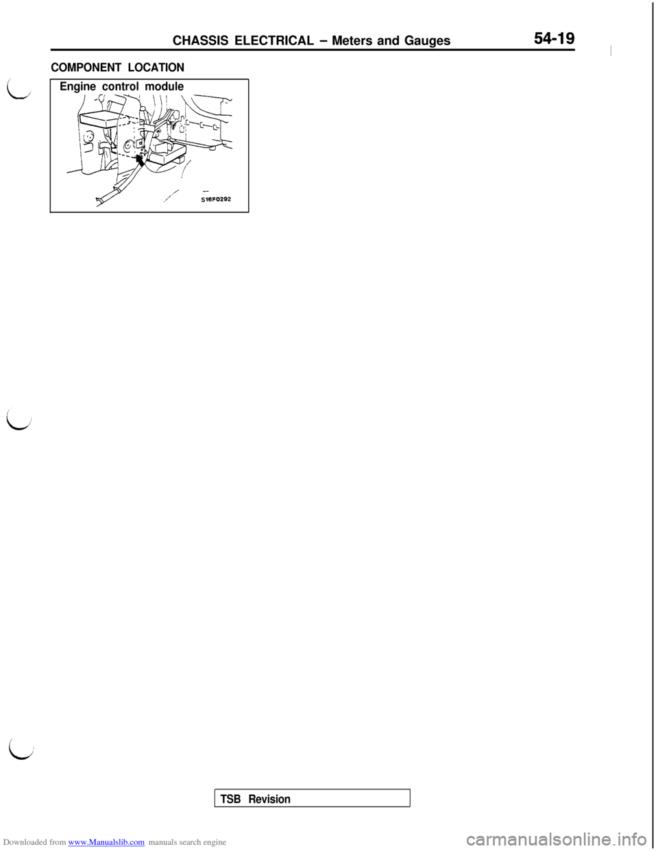
COMPONENT LOCATION
Engine control module
/ -S16FOZS2
TSB Revision
Page 516 of 738
Downloaded from www.Manualslib.com manuals search engine 54-20CHASSIS ELECTRICAL - Meters and Gauges
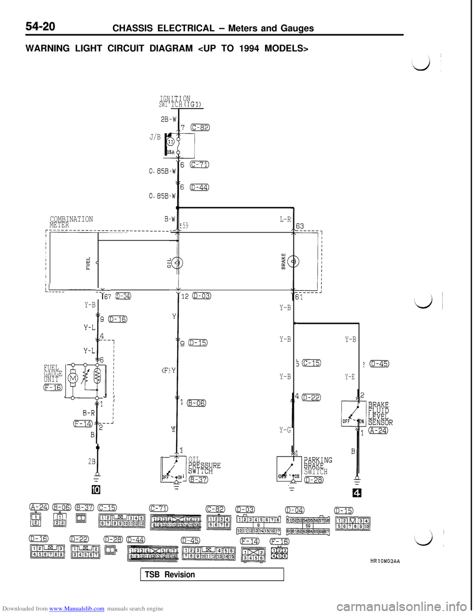
WARNING LIGHT CIRCUIT DIAGRAM
IGNSWI'IT1TCHON(IGl)
J/B
r
G
15
0.85B-
0.858.
COMBINATIONMETERB-
r------------------------------.I
I
III
I
IId <21I0III
L--- ----- -G6? ~
Y-B
GiD-15)Y-B
FUEL
GAUGE
UNIT
m
(F:J
II
2B
1
Y
r
)Y
1
Y
3
I
OIL$$#RE
Lm
L-R59
12 (D-03)
Y-B
c
I
Y-B
Y-G
/\@F&NG
OFF -SWITCHONkm
Y-B
Y-E
HRlOM03AA
TSB Revision
Page 517 of 738
Downloaded from www.Manualslib.com manuals search engine CHASSIS ELECTRICAL - Meters and Gauges54-21
L
IGN:IONsw1:-I (ST)IGNISWIT
2B-'
2B-IB-‘
z(c-31)
B-‘
1
_--11 1
J/B
r
G
151
2B-I
i
2B-I
(A-67)
2B-1
1.25B-\
1.25B-\11
/
1
kTARTERIRELAY.'OFFINim
3
G-E3 /
(c-02)3 i.--J
3G-E
EK”&#ON
l(D-15)
DIODE
E0.85B-'w
E0.85B-'
B-1r----
Ic
1 B-1IIIE
II4wsIIEW1OFF '*ON SENSORII
j Y-G
*q (A-30)
9L----~\
IN(IGl)
'(c-82)
1
i(c-71)
i(D-44)
I(D-45)
L
u(Y-G)0
D-10Y-G
66
COMBINATION
METER
(D-04)
64B
2B
1p(D-41)
28
(A-09X) (A-30)@%?')(c-02)(c-31)(c-71)(C-82)0
/
HRlOM03AB
TSB Revision
Page 518 of 738
Downloaded from www.Manualslib.com manuals search engine CHASSIS ELECTRICAL - Meters and Gauges
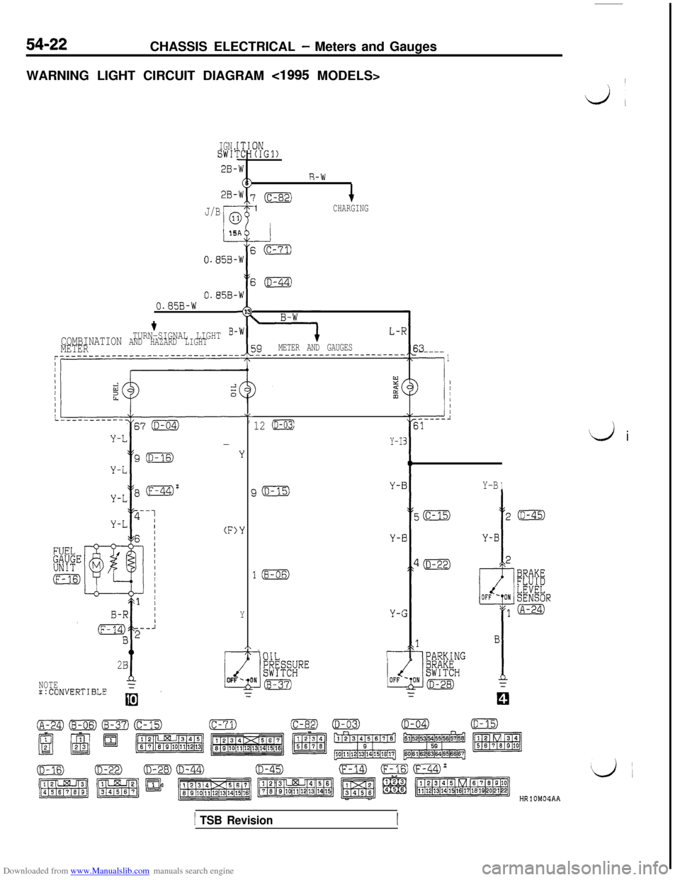
WARNING LIGHT CIRCUIT DIAGRAM
cl995 MODELS>I
dl
IGN.SWI:IN(IGl)
2B-
2B-
R-W
‘(c-82)1CHARGINGJ/B
I-15
0.858-AEW
E
,W
I
13
,W
5;(D-44)
0.858-0.85B-W
L-T
39METER AND GAUGES_______--_----------------
+TURN-SIGNAL LIGHT B-COMBINATION AND HAZARD LIGHTMETER$3-----
-.
1
--i
) ;
.-----l31
LL,
Y
‘Y
Y
,\1T-
2B
dNOTEFLOFF -0
::CONVERTIBLE=
‘d i
12 (D-03)
Y-I
Y-BIJ(D-15)Y-i
Y-i
l(B-06)
Y-C
-iniTr--
HRlOM04AA
1 TSB Revision
Page 519 of 738
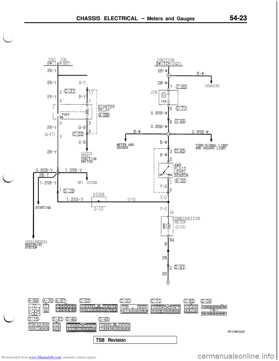
Downloaded from www.Manualslib.com manuals search engine LJ
/
:i:CHASSIS ELECTRICAL
- Meters and Gauges54-23
IGNISWI?
2B-k
2B-k
2B-k
r
2B-Y
(A-67)
2B-Y
jTARTING
SUPPLEMENTALl@TE"#'NT
IONH(ST)
B-YI
z(c-31)17-1
4B-Y I1 /
f
/STARTER--------__;RELAYsPOFFINjm
CLUTCH
PEDAL
&j+$HON
1.25B-Y
IMFI SYSTEM
IGNITIONSWITCH(IG1)I
CHARGING
J/B
s(c-71)
0.85B-W
Y
s(D-44)
0.85B-W
lmDIODE
1.25B-Yu(Y-G)Y-G0
D-10Y-G
66
A COMBINATIONMETER90(D-04)
HRlOMOIAB
TSB Revision
Page 520 of 738
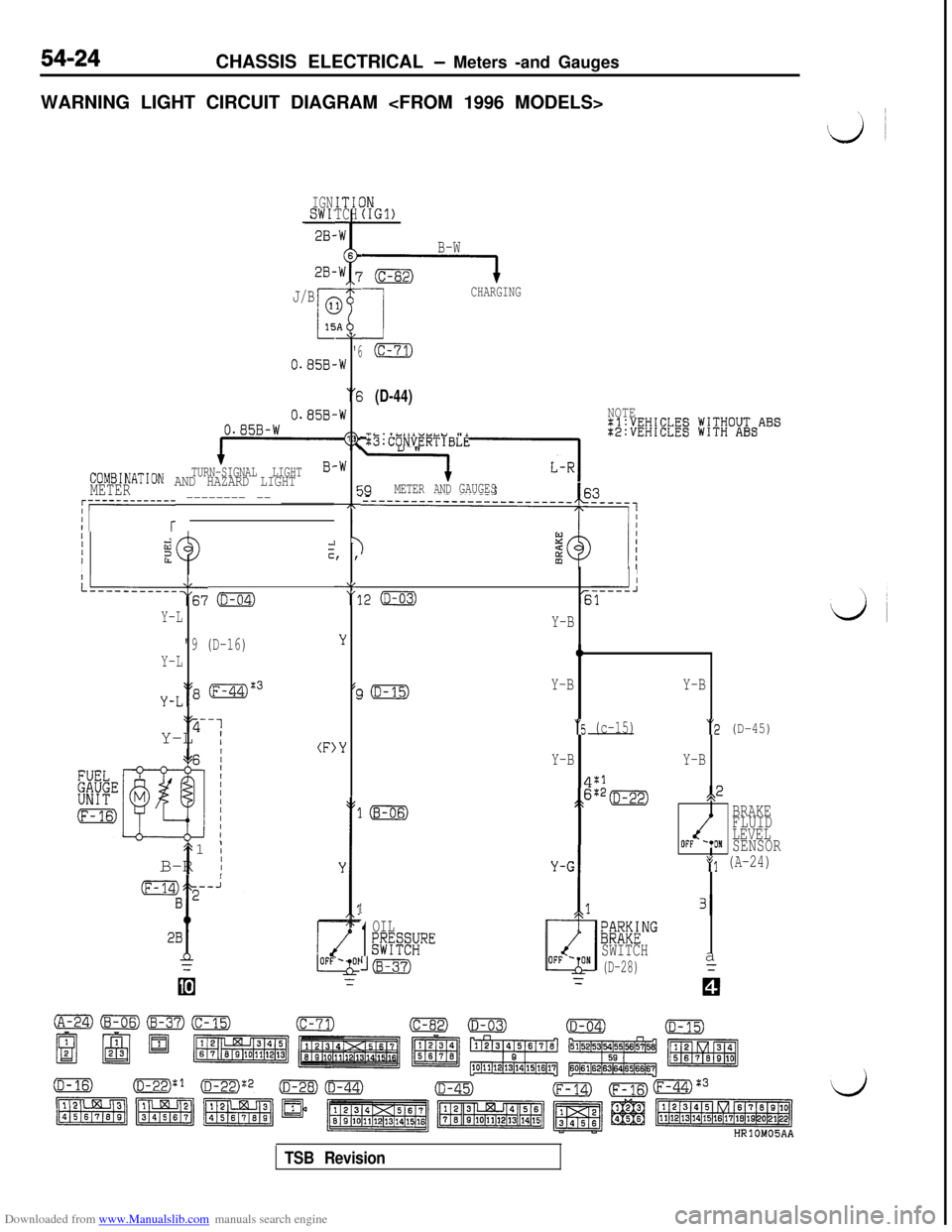
Downloaded from www.Manualslib.com manuals search engine 54-24CHASSIS ELECTRICAL - Meters -and Gauges
WARNING LIGHT CIRCUIT DIAGRAM
IGNSWI'28-ITICTCH
2B-
J/B
0.85B-
0.858,0.85B-W
TURN-SIGNAL LIGHTCOMBINATION AND HAZARD LIGHTMETER
AL
'6.W
“6
-W
13
-W
cc7T,
I y, ,
‘8"11
;;i;EW;EElg jV;V;O&ABS
:B:CONVERTIBLE
j9METER ANDGAUGES~r-----------r -------- -- _______
IIIiizzIcI
L--------‘:67 o
Y-L
"9 (D-16)
Y-L
y-L‘18 (F-44)%3‘y-1
Y-L
I(F)
t1
;B-R
I
IN(IGl)
B-W
G----l
1
CHARGING
(c-71)
(D-44)NOTE
II
.2 (D-03)-----J61
LL
'3
Y
(c
,Y
Y-B
0
Y-BY-B
“5 (c-15)“2 (D-45)
Y-BY-B
4:1
;>6:*=s,2
BRAKE
FLUID
LEVEL
OFF '*ONSENSOR
*(I (A-24)
1
1
OIL;@SRE
((B-37)
/
131
;~M&NG
SWITCH
(D-28)a
TSB Revision