MITSUBISHI 3000GT 1992 2.G Workshop Manual
Manufacturer: MITSUBISHI, Model Year: 1992, Model line: 3000GT, Model: MITSUBISHI 3000GT 1992 2.GPages: 738, PDF Size: 35.06 MB
Page 531 of 738
Downloaded from www.Manualslib.com manuals search engine CHASSIS ELECTRICAL - Lighting System
LIGHTING SYSTEM
54-35
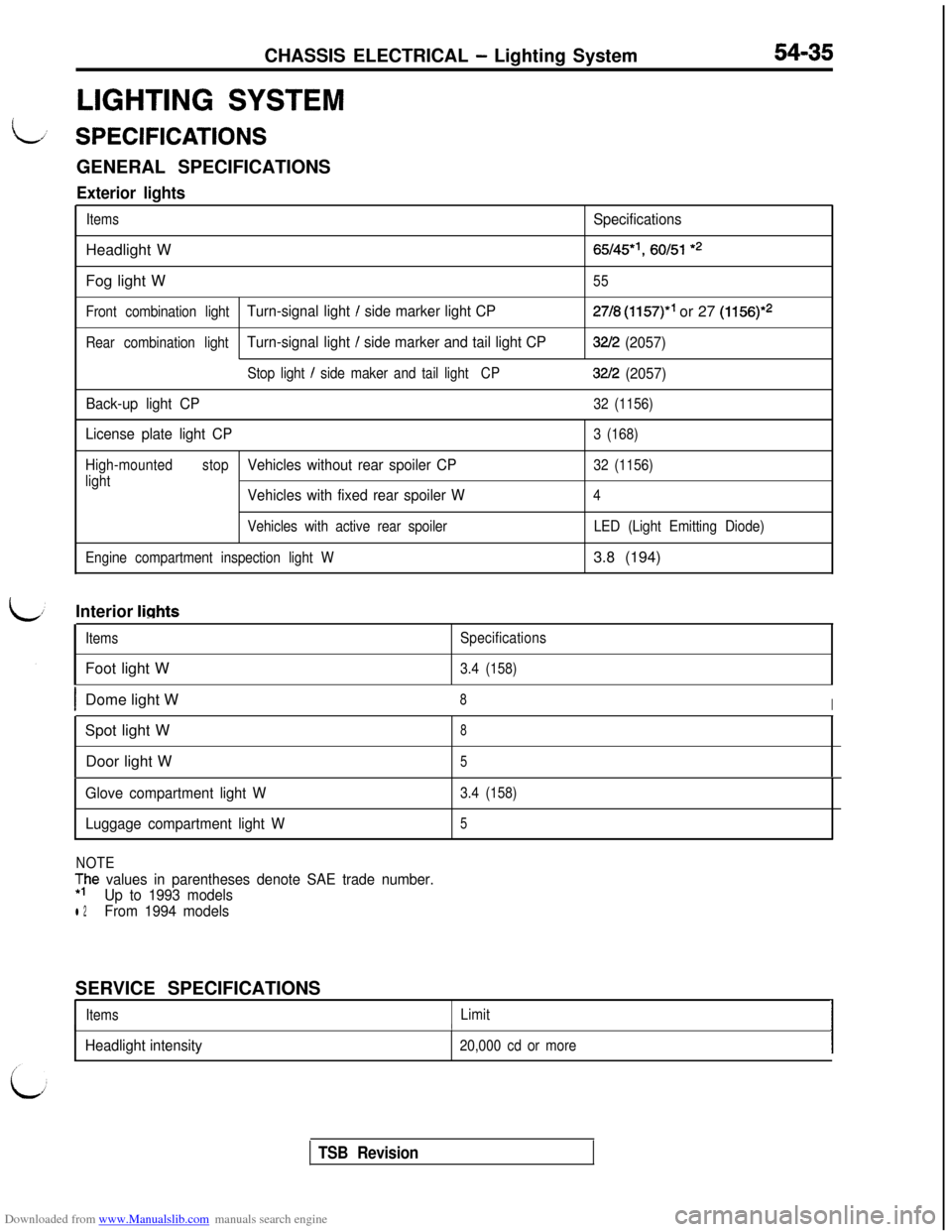
L/ SPECIFICATIONSGENERAL SPECIFICATIONS
Exterior lights
ItemsSpecificationsHeadlight W
65/45*‘, 60151 *2Fog light W
55
Front combination light
Turn-signal light / side marker light CP27/8 (1157)” or 27 (1156)*2
Rear combination lightTurn-signal light / side marker and tail light CP32/2 (2057)
Stop light / side maker and tail lightCP32/2 (2057)
Back-up light CP
32 (1156)
License plate light CP3 (168)
High-mountedstop
Vehicles without rear spoiler CP32 (1156)
light
Vehicles with fixed rear spoiler W4
Vehicles with active rear spoiler
Engine compartment inspection light WLED (Light Emitting Diode)3.8 (194)
Interior
lights
ItemsFoot light WSpecifications
3.4 (158)
IDome light W8ISpot light W
8Door light W
5
Glove compartment light W
Luggage compartment light W3.4 (158)
5
NOTE
;he values in parentheses denote SAE trade number.
Up to 1993 models
l 2From 1994 modelsSERVICE SPECIFICATIONS
ItemsLimitI
Headlight intensity
I
20,000 cd or moreI
TSB Revision
Page 532 of 738
Downloaded from www.Manualslib.com manuals search engine 54-36CHASSIS ELECTRICAL - Lighting System
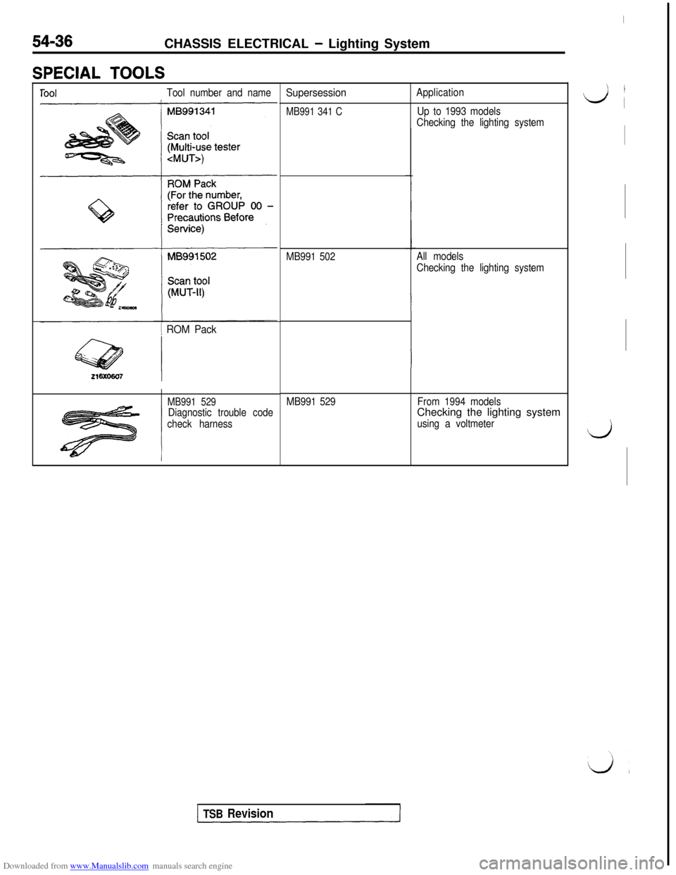
SPECIAL TOOLS
ToolTool number and name
1 ROM Pack
MB991 529Diagnostic trouble code
check harness
Supersession
MB991 341 C
Application
Up to 1993 models
Checking the lighting system
MB991 502All models
Checking the lighting system
MB991 529From 1994 modelsChecking the lighting system
using a voltmeter
I
‘, I
L/i
1
d
TSB Revision
Page 533 of 738
Downloaded from www.Manualslib.com manuals search engine CHASSIS ELECTRICAL - Lighting System54-37
i
TROUBLESHOOTING
LHEADLIGHT
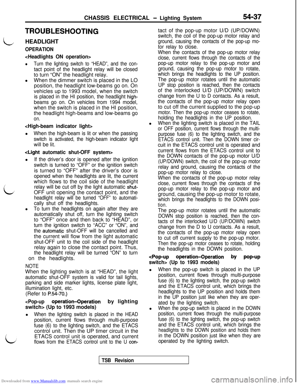
OPERATION
lTurn the lighting switch to “HEAD”, and the con-
tact point of the headlight relay will be closedto turn “ON” the headlight relay.
lWhen the dimmer switch is placed in the LO
position, the headlight low-beams go on. On
vehicles up to 1993 model, when the switch
is placed in the HI position, the headlight high-
beams go on. On vehicles from 1994 model,when the switch is placed in the HI position,
the headlight high-beams and low-beams go
on.
When the high-beam is lit or when the passing
switch is activated, the high-beam indicator lightwill be lit.
If the driver’s door is opened after the ignition
switch is turned to “OFF” or the ignition switchis turned to “OFF” after the driver’s door is
opened when the headlights are lit, the currentwhich flows to the coil side of the headlight
relay will be cut off by the light automatic shut-OFF unit opening the contact point, and the
headlight relay will be turned “OFF” to automati-
cally shut off the headlights.l
To turn the headlights on again after they are
automatically shut off, turn the lighting switchto “OFF” once and then back to “HEAD”, or
turn the ignition switch to “ACC” or “ON”, and
the
aut0mati.c shut-OFF will be cancelled andthe current will flow from the light automatic
shut-OFF unit to the coil side of the headlightrelay again to close the contact point. Thus,
the headlight relay will be turned “ON” to turnon the headlights.
NOTEWhen the lighting switch is at “HEAD”, the light
automatic shut-OFF system is valid for tail lights,
parking and side marker lights, license plate light,
illumination light, etc.(Refer to
P.54-70.)
l
When the lighting switch is placed in the HEAD
position, current flows through multi-purpose
fuse (6) to the lighting switch, and the ETACScontrol unit. Then the UP timer circuit in the
LETACS control unit is operated, and currentflows from the ETACS control unit to the U con-tact of the pop-up motor U/D (UP/DOWN)
switch, the coil of the pop-up motor relay and
ground, causing the contacts of the pop-up mo-
tor relay to close.
When the contacts of the pop-up motor relay
close, current flows through the contacts of the
pop-up motor relay to the pop-up motor and
ground, causing the pop-up motor to rotate,
which brings the headlights to the UP position.
The pop-up motor rotates until the automatic
UP stop position is reached, then the contactsof the interlocked U/D (UP/DOWN) switch
change from the U to D contacts. As a result,
the contacts of the pop-up motor relay opento cut off the current supplied to the pop-up
motor. Then the pop-up motor ceases to rotate,
holding the headlights in the UP position.l
When the lighting switch is placed in the TAIL
or OFF position, current flows through the multi-
purpose fuse (6) to the lighting switch, and the
ETACS control unit. Then the DOWN timer cir-
cuit in the ETACS control unit is operated and
current flows from the ETACS control unit to
the DOWN contacts of the pop-up motor U/D
(UP/DOWN) switch, the coil of the pop-up motor
relay and ground, causing the contacts of the
pop-up motor relay to close.
When the contacts of the pop-up motor relay
close, current flows through the contacts of the
pop-up motor relay to the pop-up motor andground, causing the pop-up motor to rotate,
which brings the headlights to the DOWN posi-
tion.
The pop-up motor rotates until the automatic
DOWN stop position is reached, then the con-
tacts of the interlocked U/D (UP/DOWN) switch
change from the D to U contacts. As a result,
the contacts of the pop-up motor relay open
to cut off current supply to the pop-up motor.
Then the pop-up motor ceases to rotate, holding
the headlights in the DOWN position.
When the pop-up switch is placed in the UP
position, current flows through multi-purpose
fuse (6) to the lighting switch, the pop-up switch
and the ETACS control unit, which brings the
headlights to the UP position and holds them
in the UP position just like when they are oper-
ated by the lighting switch.l
When the pop-up switch is placed in the DOWN
position, current flows through the multi-purpose
fuse (6) to the lighting switch, the pop-up switch
and the ETACS control unit, which brings the
headlights to the DOWN position and holds them
in the DOWN position just like when they are
operated by the lighting switch.
TSB Revision
Page 534 of 738
Downloaded from www.Manualslib.com manuals search engine CHASSIS ELECTRICAL - Liahting System
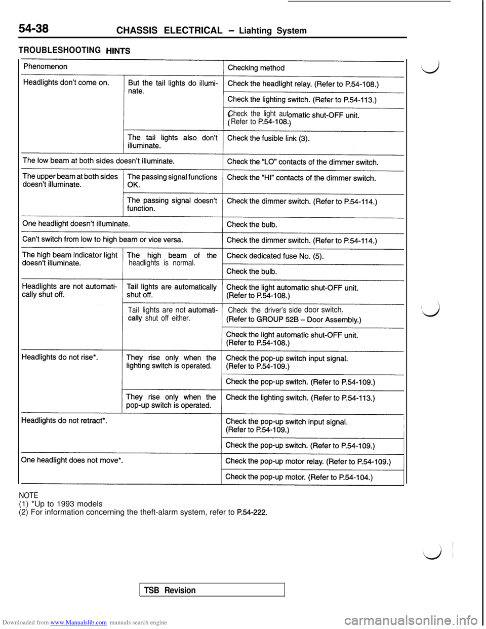
TROUBLESHOOTING
Check the light aut
Refer to
P.54-108.
headlights is normal.
Taillights are not automati-
Check the driver’ssidedoor switch.tally
shut off either.
NOTE(1) *Up to 1993 models
(2) For information concerning the theft-alarm system, refer to
P.54-222.
TSB Revision
Page 535 of 738
Downloaded from www.Manualslib.com manuals search engine CHASSIS ELECTRICAL - Lighting System54-39
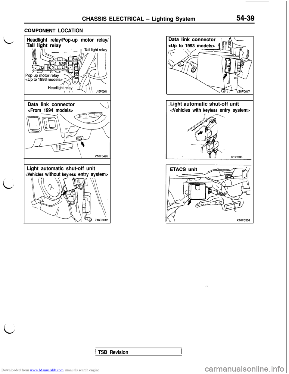
ZOMPONENT LOCATION
Headlight relay/Pop-up motor relay/
HeadliiW,$w, q\\ u,6F026,
Data link connector
\V16FO49E
Light automatic shut-off unit
-Light automatic shut-off unit
i
1 TSB Revision
Page 536 of 738
Downloaded from www.Manualslib.com manuals search engine 54-40CHASSIS ELECTRICAL - Lighting System
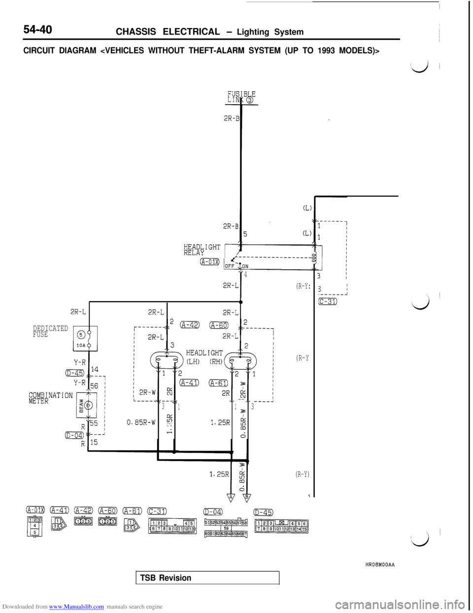
CIRCUIT DIAGRAM
F5L-----c--_2,------A31133
%/
c-uA
1.25R g
d
2R-
2R-I
;~~;\I""'
rI
I
4
2R-L
0
2R-L2R-L2R-L
DEDICATEDFUSE2R-LII
(R-Y:
(R-Y
(R-Y)
TSB Revision3
I/.------A
(c-31)HR08MOOAA
Page 537 of 738
Downloaded from www.Manualslib.com manuals search engine CHASSIS ELECTRICAL - Lighting System54-41
(L
1
IGNI'ISWITC
2B-rh(c-77)
0.85B-t
16(c-83)
R-B
0.85B-W
R-B
73
T
bJ-
1
Y
FUSIBLE LINK@I5W-B
J/B
G-Y
I----11 2
R-Y R
c
T
2
3
-
'4
.2 (E-21)@SWITCH
(E-17)(E-21)
1
(A-11X)
IOD ORSTORAGE
CONNECTOR
LIGHT
AUTOMATIC
SHUT-OFF
UNIT
(E-17)
HROEMOOAB
1 TSB RevisionI
Page 538 of 738
Downloaded from www.Manualslib.com manuals search engine 54-42CHASSIS ELECTRICAL - Lighting System
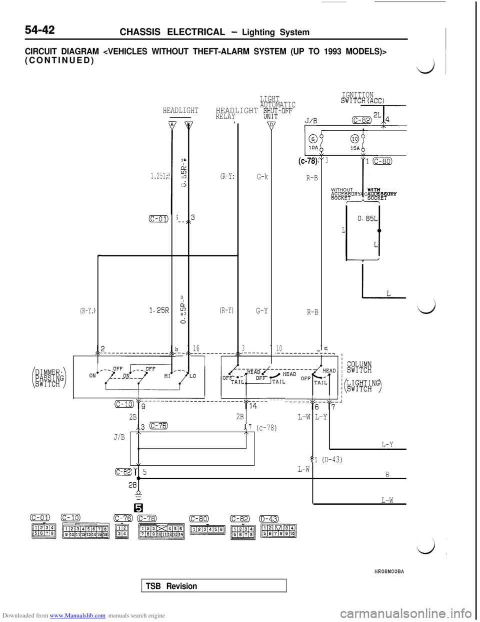
CIRCUIT DIAGRAM
(R-Y.
HEADLIGHT
1.251;
(c-01)j-_,\
L
c
)1.25R
B3
EI
z:aJ
C5
LIGHTIGNITION
AUTOMATICSWITCH(ACC)
HEADLIGHT gWi-i;-OFFRELAY7,J/B -7
(R-Y:I
@0
10A15AY(c-78)\I:3
G-k
R-BWITHOUTP.~~“.~~ORY
-3
I
P;
a(R-Y)G-YR-B
i;3
16310.-_.------.-----------
7 r
-__-7
(c-01)
l(c-80)
iWITH
ACCESSORY*ET
m&c-----------------------~q-6-- ---- ------""s--"F-'
2B2BL-W L-Y
,,3 mx.7 (c-78)
J/B/\I\
t.L-Y
\/St1 (D-43)
(c-82)“ 5L-W
0B28n
0
L-W
HROEMOOBA
TSB Revision
Page 539 of 738
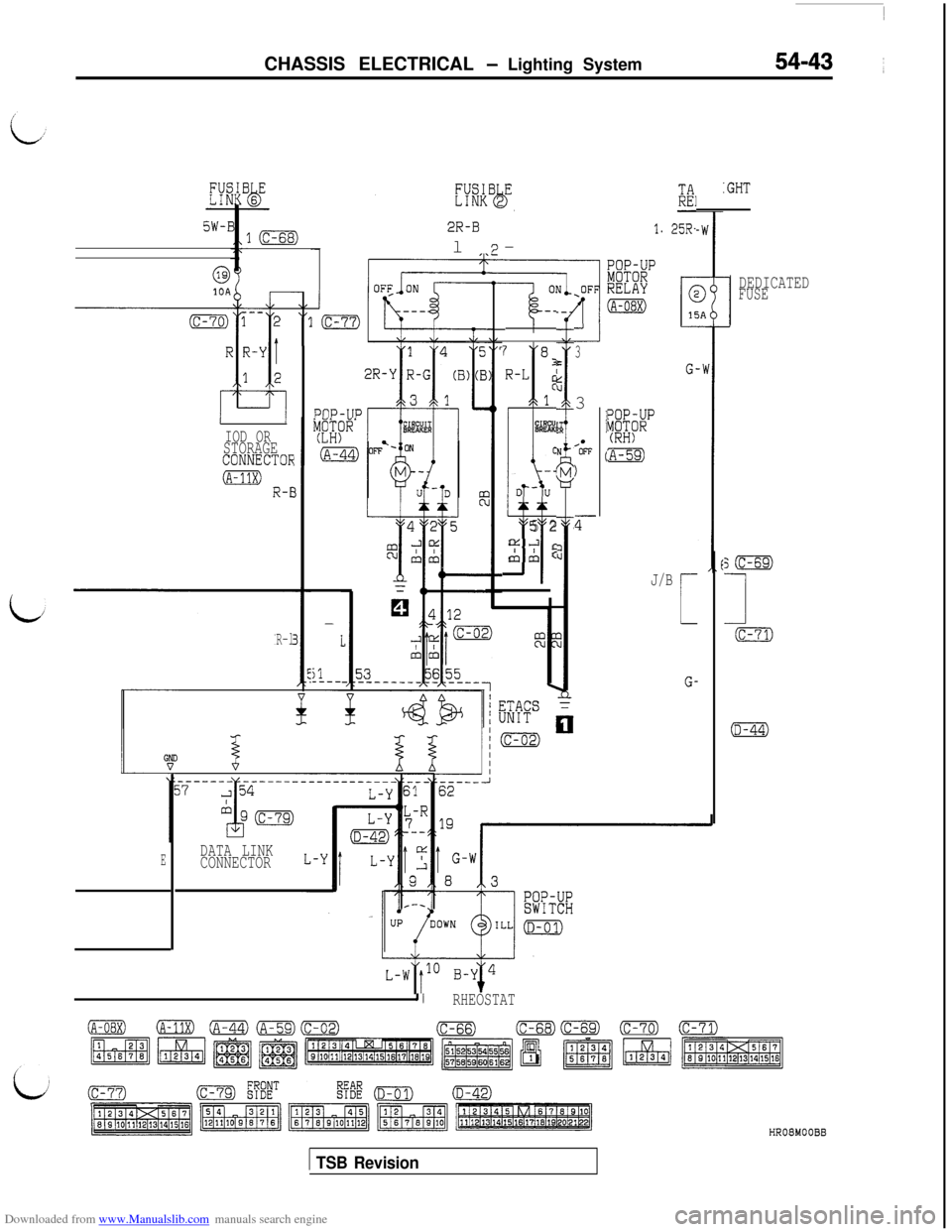
Downloaded from www.Manualslib.com manuals search engine CHASSIS ELECTRICAL - Lighting System54-43 ~
?IIK:GHT
l(c-68)2R-Bl-'I. 25R-
I7
@10ADEDICATEDFUSE-_
-kz-.-l7 8I-L:1
%%!
C
u
-4
D-u
5 2a.3
&A:PllP-TIP
33
/*OFF
)
z--
EYi~p(RH)
:A-59)
J/B
L-
G-
IOD ORSTORAGECONNECTOk
0 R-E
R-l
;m
1
(c-71)
(D-44)
-
I
il_---
DATA LINK
CONNECTORE
I/RHEOSTAT
1 TSB RevisionHR08MOOBB
Page 540 of 738
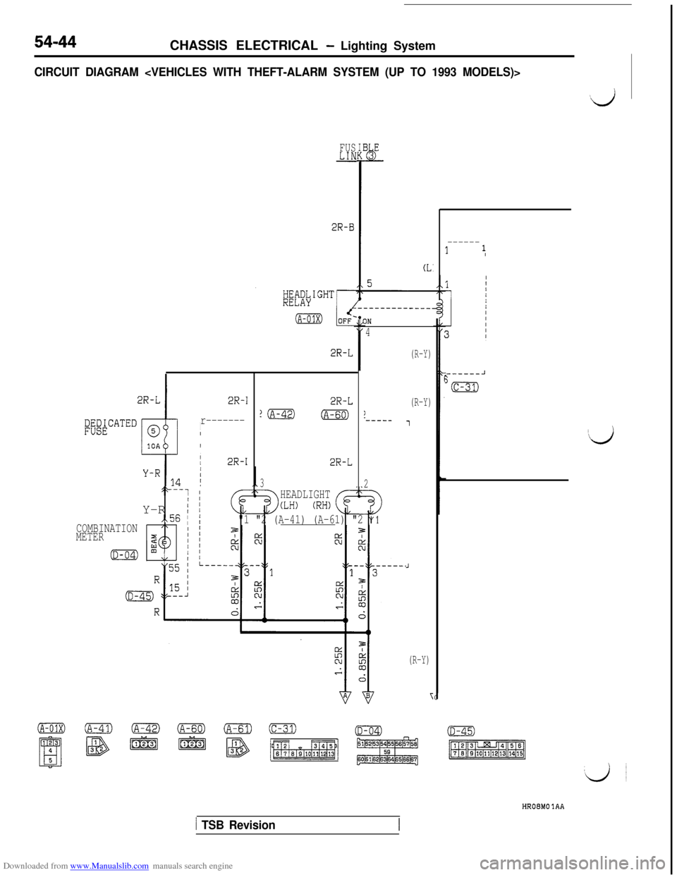
Downloaded from www.Manualslib.com manuals search engine 54-44CHASSIS ELECTRICAL - Lighting System
CIRCUIT DIAGRAM
;;E#ATED
2R-I
r-------II
I
,
/I2R-I
FUS&IJ
2R-B
2R-L
2R-L
?m(A-60)
2R-L
3
4
)._____
2
*--1 1/ 1HEADLIGHTY-R
i j(LH) (RH)
.,56 IjCOMBINATION"1 "2 (A-41) (A-61) "2 "1
METER
(R-Y)
(R-Y)
1
J
(R-Y)
OO(A-42)~~(C-31)(D-04)
El
‘I35m lzi@I - B -1
C
------11 I
------J
3m
‘d
(D-45)
pT%EEEq
HROBMO 1AA
1 TSB Revision