switch MITSUBISHI 3000GT 1995 2.G Workshop Manual
[x] Cancel search | Manufacturer: MITSUBISHI, Model Year: 1995, Model line: 3000GT, Model: MITSUBISHI 3000GT 1995 2.GPages: 738, PDF Size: 35.06 MB
Page 502 of 738
Downloaded from www.Manualslib.com manuals search engine 54-6CHASSIS ELECTRICAL - Ignition Switch
IGNITION SWITCHSPECIAL
TOOL
ToolTool number and nameSupersessionApplication
MB990803
Steering wheel pullerGeneral service toolRemoval of steering wheel
IGNITION SWITCHREMOVAL AND INSTALLATION
40 Nm29 ft.lbs.6 Nm
6
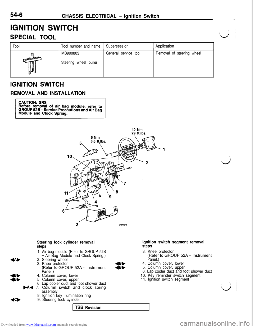
Steering lock cylinder removalsteps
Ignition switch segment removalsteps
1. Air bag module (Refer to GROUP 52B
4Ab
- Air Bag Module and Clock Spring.)3. Knee protector
2. Steering wheel(Refer to GROUP 52A - Instrument
3. Knee protector
Panel.)
LRedE;)to GROUP 52A - Instrument:i:4. Column cover, lower
5. Column cover, upper
:::4. Column cover, lower6. Lap cooler duct and foot shower duct
5. Column cover, upper10. Key reminder switch segment
6. Lap cooler duct and foot shower duct11. Ignition switch segment
,A+ 7. Column switch and clock springassembly
NW
8. Ignition key illumination ring
9. Steering lock cylinder
TSB Revision
Page 503 of 738
Downloaded from www.Manualslib.com manuals search engine CHASSIS ELECTRICAL - Ignition Switch54-7REMOVAL SERVICE POINTS
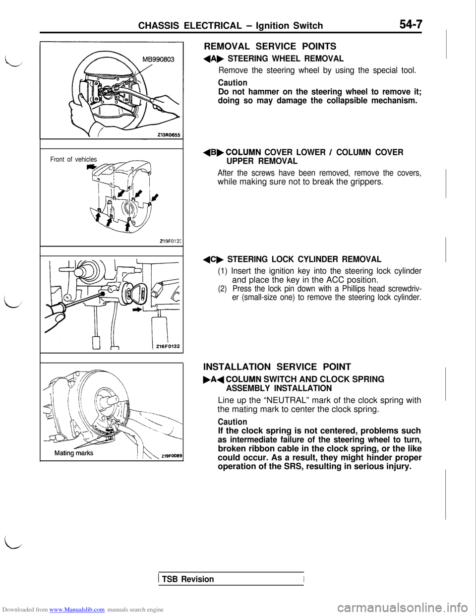
+A, STEERING WHEEL REMOVAL
Remove the steering wheel by using the special tool.
Caution
Do not hammer on the steering wheel to remove it;
doing so may damage the collapsible mechanism.
Front of vehicles
219FO12:
+B,COLUMN COVER LOWER / COLUMN COVER
UPPER REMOVAL
After the screws have been removed, remove the covers,while making sure not to break the grippers.
+C, STEERING LOCK CYLINDER REMOVAL
(1) Insert the ignition key into the steering lock cylinderand place the key in the ACC position.
(2)Press the lock pin down with a Phillips head screwdriv-
er (small-size one) to remove the steering lock cylinder.INSTALLATION SERVICE POINT
.A+COLUMN SWITCH AND CLOCK SPRING
ASSEMBLY INSTALLATIONLine up the “NEUTRAL” mark of the clock spring with
the mating mark to center the clock spring.
CautionIf the clock spring is not centered, problems such
as intermediate failure of the steering wheel to turn,broken ribbon cable in the clock spring, or the like
could occur. As a result, they might hinder proper
operation of the SRS, resulting in serious injury.
iI
1 TSB RevisionI
Page 504 of 738
Downloaded from www.Manualslib.com manuals search engine 54-8CHASSIS ELECTRICAL - Ignition Switch
216AO57000002296INSPECTION
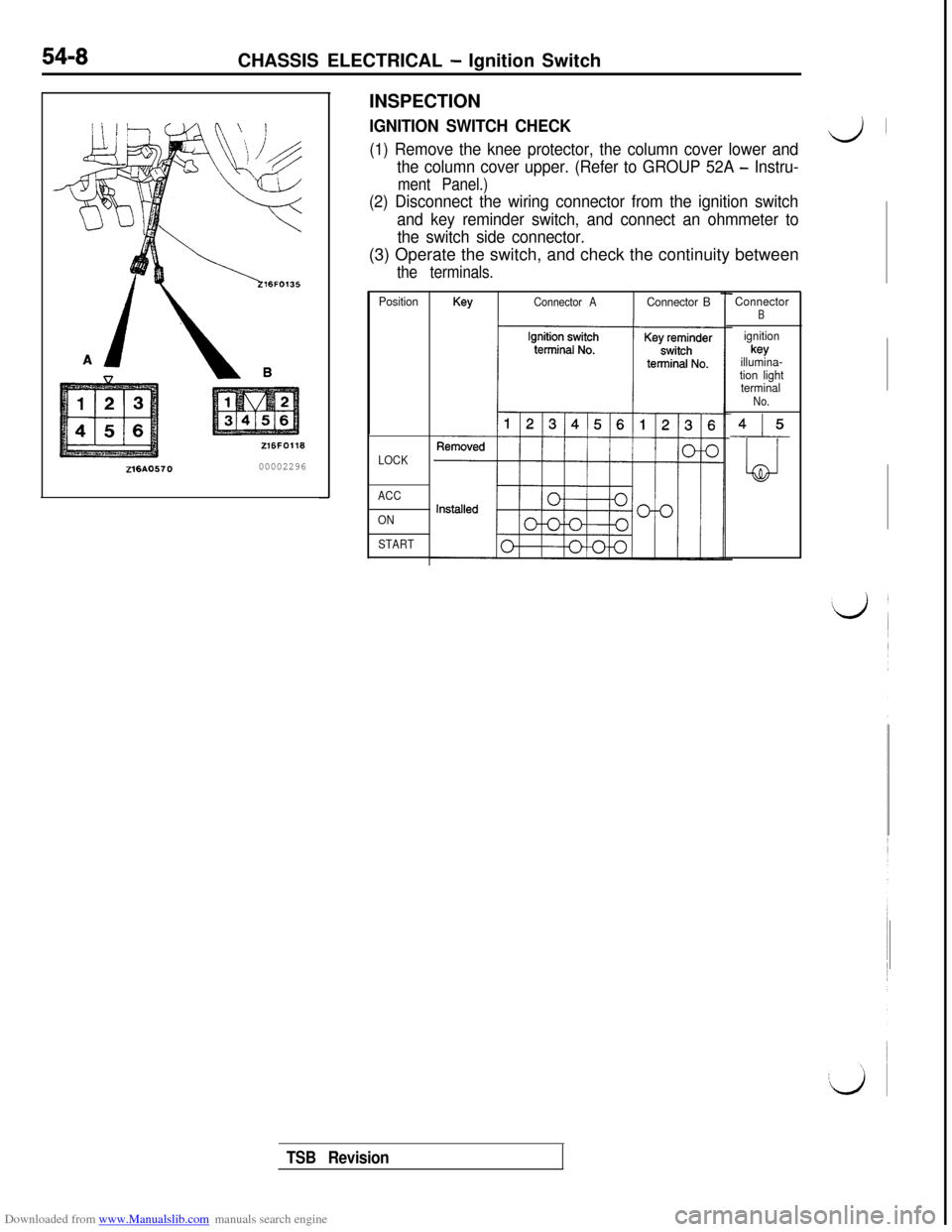
IGNITION SWITCH CHECK
(1) Remove the knee protector, the column cover lower andd’
the column cover upper. (Refer to GROUP 52A - Instru-
ment Panel.)
(2) Disconnect the wiring connector from the ignition switch
and key reminder switch, and connect an ohmmeter to
the switch side connector.(3) Operate the switch, and check the continuity between
the terminals.
PositionKeyConnector AConnector B
LOCK
ACC
ON
START
ConnectorB
ignitionkey
illumina-
tion light
terminal
No.
415
LJ
TSB Revision
Page 508 of 738
Downloaded from www.Manualslib.com manuals search engine 54-12CHASSIS ELECTRICAL - Meters and Gauges
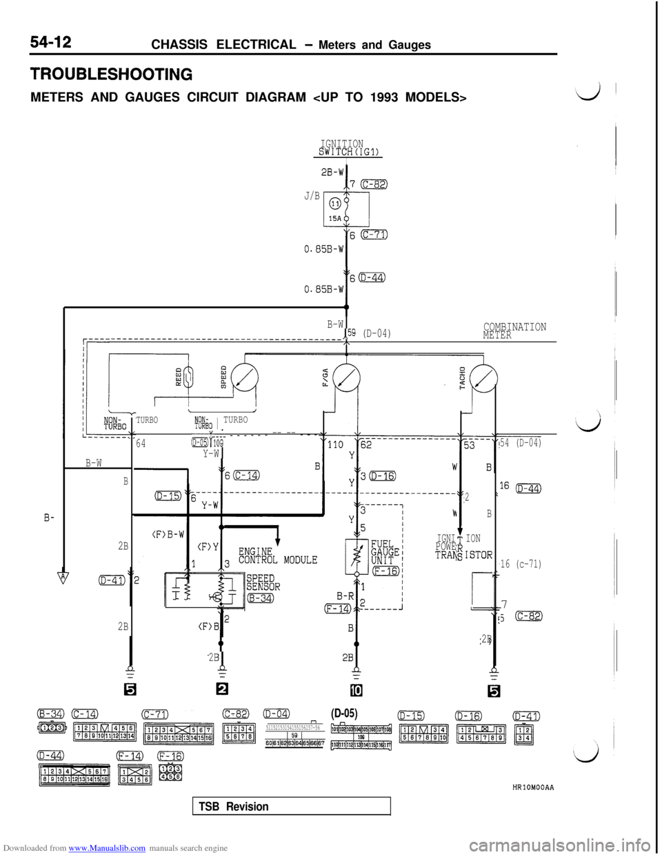
TROUBLESHOOTINGMETERS AND GAUGES CIRCUIT DIAGRAM
IGNITIONSWITCH(IG1)I
J/B
I60
0.05B-W
t
S(D-44)
O.B5B-W
B-W,,59 (D-04)COMBINATION
q----_____----____-_------~~~~~--~-------~~~~~METER,\
r--t-- I
2
B
ION
ISTOR
r
2B
TURBOLJt@io 1 TURBO
64&&- - - - - - - -- -- - - -
Y-W
54 (D-04)
16 (D-44)
16 (c-71)7
J(c-82)
B-W
B
b
IGNIPOWETRAN
(F)B
B-
2B
2B
2Bd
0
(c-82)mn51152153154155156157~561 59 160~61~62~S~s4~65~66~6?
(D-05)HRlOMOOAA
TSB Revision
Page 512 of 738
Downloaded from www.Manualslib.com manuals search engine 54-16CHASSIS ELECTRICAL - Meters and Gauges
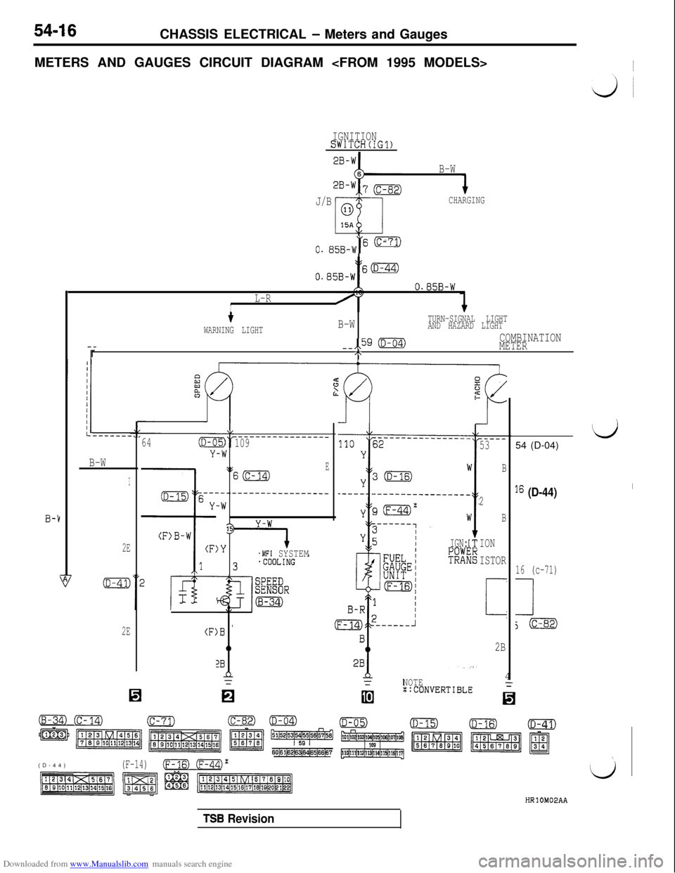
METERS AND GAUGES CIRCUIT DIAGRAM
IGNITIONSWITCH(IG1)
B-W
J/B
CHARGING
\,
0. 85B-W“' -
tO.B5B-Ws(D-44)
B-1
O.B5B-W
L-RI
--r
tB-WTURN-SIGNAL LIGHT
WARNING LIGHTAND HAZARD LIGHT
--,,59 (D-04)COMBINATION
METER
/\
B-W
I
2E
2E(F:
64(D-C
Y
\L
-W
\:
---.
-W
13
)Y
)B '
0
2Bn=
-------------____109
ES(c-14)
--------------___
.MFI SYSTEMIGN:
R3
(B-34) (c-14)(c-71)
m m m z ~~~~5&4
60161(6216~64165166167(D-44)
(F-14)(Fm (ml'
NOTE4::CONVERTIBLE
-..I
-----53
B
2
B
ION
ISTOR
i
2B
‘d54 (D-04)
I6 (D-44)I
16 (c-71)
1
j(c-82)
TSB Revision
Page 514 of 738
Downloaded from www.Manualslib.com manuals search engine 54-18CHASSIS ELECTRICAL - Meters and Gauges
OPERATION
When the ignition key is at the “ON” position,the fuel gauge is activated.
l
When there is much fuel, the unit’s resistanceis small and the current flowing in the circuit
is great, so the gauge’s indicator indicates inthe “F” area.
l When there is little fuel, the unit’s resistance
is high and the current flowing in the circuit
is small, so the gauge’s indicator indicates inthe
“E” area.
lWhen the ignition key is at the “ON” position,
the engine coolant temperature gauge is acti-
vated.l
When the engine coolant temperature is high,
the unit’s resistance is low and there is a greatflow of current in the circuit, so the gauge’s
indicator indicates in the “H” area.
l
When the engine coolant temperature is low,
the unit’s resistance is high and there is a smallflow of current in the circuit, so the gauge’s
indicator indicates in the “C” area.
vehicle speed, and vehicle-speed signals areinput to systems (the MFI system, etc.) that
regulate according to the vehicle speed.
TROUBLESHOOTING HINTS
1.The fuel gauge doesn’t function, or shows the
incorrect indication.
(1) Disconnect the connector of the fuel pumpand gauge unit assembly; the ‘F” side is
indicated when terminal (5) is then
grounded.l Check the fuel gauge.
2.The engine coolant temperature gauge doesn’t
function, or shows the incorrect indication.
(1)The “l-l” side is indicated when the connector
of the engine coolant temperature gauge
unit is disconnected and then grounded.l
Check the engine coolant temperature
gauge unit.
3. Systems dependent upon control according to
the vehicle speed do not function correctly.l Check the reed switch (mechanical
speedometer type)l Check the speed sensor (electrical
speedometer type)
coil pressure gauge>l
When the ignition key is at the “ON” position,
the oil pressure gauge is activated.
lWhen oil pressure is high, the internal contacts
of the gauge unit are kept closed for a longerperiod of time. This causes more current to
flow in the circuit, and the gauge pointer swings
to the high pressure side.
lWhen oil pressure is low, the internal contactsof the gauge unit open in a shorter period of
time. Therefore, there is less current flowing
in the circuit and the gauge pointer swings to
the low pressure side.
lWhen the ignition key is set to the “ON” position,the gauge indicator will be at
“0”.l
When the engine is started, the indicator will
move from
“0” to the minus (-) side, and then,as the boost level increases, it will move to
the plus
(+) side.
position, the voltage gauge operates and indi-
cates a battery voltage of approximately 12 V.l
When the engine is started, the voltage gauge
indicates a battery voltage of 12 to 16 V, indicat-ing that the battery is on charge.
4. The oil pressure gauge doesn’t function, or
shows the incorrect indication.
(1)The “H” side is indicated when the connectorof the oil pressure gauge unit is discon-
nected and then grounded.l Check the oil pressure gauge unit.
5.The meter illumination light does not illuminate.
(1) The tail lights illuminate.l Check the rheostat.
6. The voltage gauge doesn’t function, or shows
the incorrect indication.l Check the voltage gauge.
TSB Revision
Page 516 of 738
Downloaded from www.Manualslib.com manuals search engine 54-20CHASSIS ELECTRICAL - Meters and Gauges
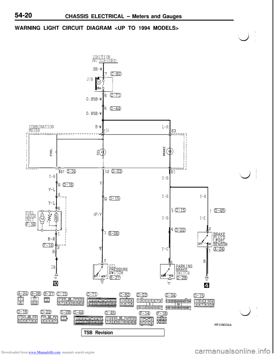
WARNING LIGHT CIRCUIT DIAGRAM
IGNSWI'IT1TCHON(IGl)
J/B
r
G
15
0.85B-
0.858.
COMBINATIONMETERB-
r------------------------------.I
I
III
I
IId <21I0III
L--- ----- -G6? ~
Y-B
GiD-15)Y-B
FUEL
GAUGE
UNIT
m
(F:J
II
2B
1
Y
r
)Y
1
Y
3
I
OIL$$#RE
Lm
L-R59
12 (D-03)
Y-B
c
I
Y-B
Y-G
/\@F&NG
OFF -SWITCHONkm
Y-B
Y-E
HRlOM03AA
TSB Revision
Page 519 of 738
Downloaded from www.Manualslib.com manuals search engine LJ
/
:i:CHASSIS ELECTRICAL
- Meters and Gauges54-23
IGNISWI?
2B-k
2B-k
2B-k
r
2B-Y
(A-67)
2B-Y
jTARTING
SUPPLEMENTALl@TE"#'NT
IONH(ST)
B-YI
z(c-31)17-1
4B-Y I1 /
f
/STARTER--------__;RELAYsPOFFINjm
CLUTCH
PEDAL
&j+$HON
1.25B-Y
IMFI SYSTEM
IGNITIONSWITCH(IG1)I
CHARGING
J/B
s(c-71)
0.85B-W
Y
s(D-44)
0.85B-W
lmDIODE
1.25B-Yu(Y-G)Y-G0
D-10Y-G
66
A COMBINATIONMETER90(D-04)
HRlOMOIAB
TSB Revision
Page 520 of 738
Downloaded from www.Manualslib.com manuals search engine 54-24CHASSIS ELECTRICAL - Meters -and Gauges
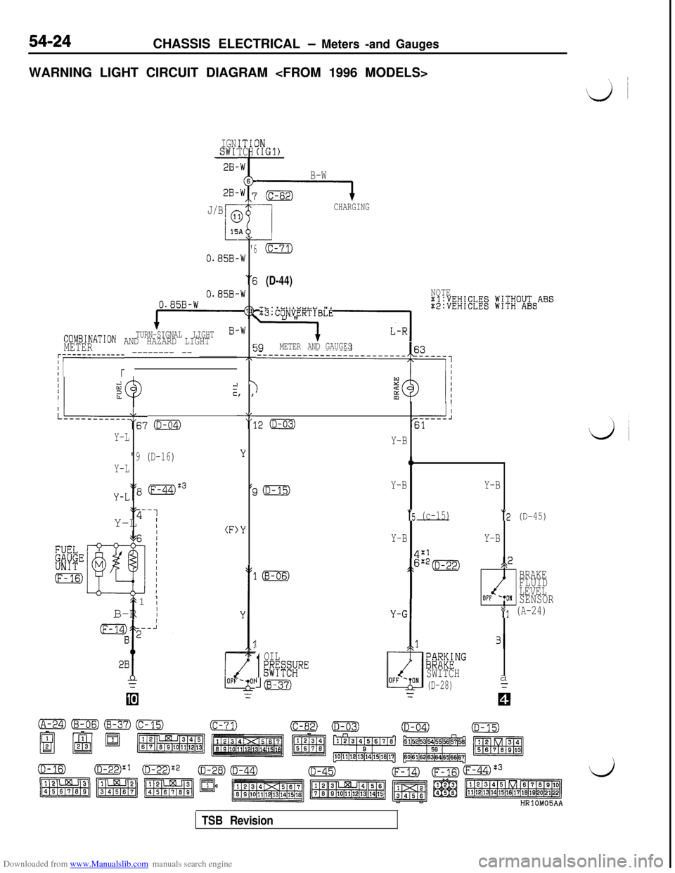
WARNING LIGHT CIRCUIT DIAGRAM
IGNSWI'28-ITICTCH
2B-
J/B
0.85B-
0.858,0.85B-W
TURN-SIGNAL LIGHTCOMBINATION AND HAZARD LIGHTMETER
AL
'6.W
“6
-W
13
-W
cc7T,
I y, ,
‘8"11
;;i;EW;EElg jV;V;O&ABS
:B:CONVERTIBLE
j9METER ANDGAUGES~r-----------r -------- -- _______
IIIiizzIcI
L--------‘:67 o
Y-L
"9 (D-16)
Y-L
y-L‘18 (F-44)%3‘y-1
Y-L
I(F)
t1
;B-R
I
IN(IGl)
B-W
G----l
1
CHARGING
(c-71)
(D-44)NOTE
II
.2 (D-03)-----J61
LL
'3
Y
(c
,Y
Y-B
0
Y-BY-B
“5 (c-15)“2 (D-45)
Y-BY-B
4:1
;>6:*=s,2
BRAKE
FLUID
LEVEL
OFF '*ONSENSOR
*(I (A-24)
1
1
OIL;@SRE
((B-37)
/
131
;~M&NG
SWITCH
(D-28)a
TSB Revision
Page 521 of 738
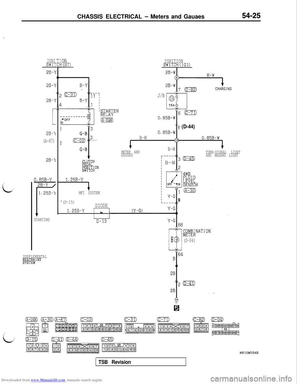
Downloaded from www.Manualslib.com manuals search engine CHASSIS ELECTRICAL - Meters and Gauaes
i
L/
IGNISW17
2B-\1
28-l
2B-\I
2B-‘1
(A-67)
2B-Y
STARTING
SUPPLEMENTAL
~E~&~J$NT
----------.+OFFIN
13
i
G-B
3(c-02) 3--
G-B
1.25B-Y
+MFI SYSTEM
'(D-15)DIODE
1.25B-Yu
I
IGNITIONSWITCH(IG1)
J/B
ml
0
15A“6
(D-44)
0.85B-W
B-W(130.85B-W
METER AND
GAUGESB-WTURN-SIGNAL LIGHT
r----+$30AND HAZARD LIGHT
i B-W
9
i;yEKNATION
(D-04)
HRlOM05AB
TSB Revision