switch MITSUBISHI 3000GT 1995 2.G Workshop Manual
[x] Cancel search | Manufacturer: MITSUBISHI, Model Year: 1995, Model line: 3000GT, Model: MITSUBISHI 3000GT 1995 2.GPages: 738, PDF Size: 35.06 MB
Page 523 of 738
Downloaded from www.Manualslib.com manuals search engine I,;CHASSIS ELECTRICAL
- Meters and Gauges54-27
c I\\ zl6F024;
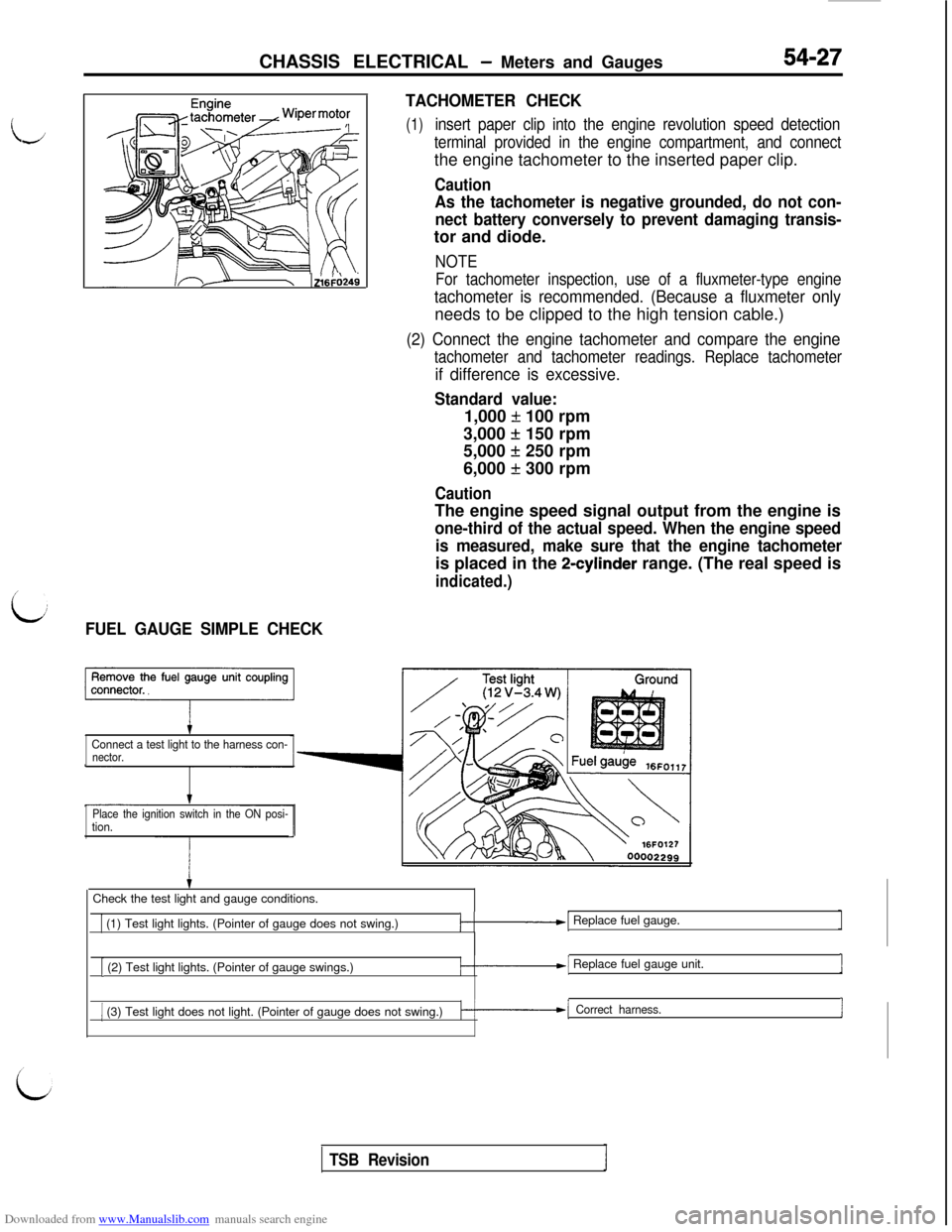
L:FUEL GAUGE SIMPLE CHECKTACHOMETER CHECK
(1)insert paper clip into the engine revolution speed detection
terminal provided in the engine compartment, and connectthe engine tachometer to the inserted paper clip.
Caution
As the tachometer is negative grounded, do not con-
nect battery conversely to prevent damaging transis-tor and diode.
NOTE
For tachometer inspection, use of a fluxmeter-type engine
tachometer is recommended. (Because a fluxmeter onlyneeds to be clipped to the high tension cable.)
(2) Connect the engine tachometer and compare the engine
tachometer and tachometer readings. Replace tachometer
if difference is excessive.
Standard value:1,000
f 100 rpm
3,000
+ 150 rpm
5,000
f 250 rpm
6,000
f 300 rpm
CautionThe engine speed signal output from the engine is
one-third of the actual speed. When the engine speed
is measured, make sure that the engine tachometeris placed in the
2-cylinder range. (The real speed is
indicated.)
Connect a test light to the harness con-nector.
Place the ignition switch in the ON posi-
tion.Check the test light and gauge conditions.
1 (1) Test light lights. (Pointer of gauge does not swing.)/-.-I Replace fuel gauge.
[ (2) Test light lights. (Pointer of gauge swings.)/-.--I Replace fuel gauge unit.1
1 (3) Test light does not light. (Pointer of gauge does not swing.)k-1 Correct harness.I
TSB Revision
Page 525 of 738
Downloaded from www.Manualslib.com manuals search engine CHASSIS ELECTRICAL - Meters and Gauaes
i
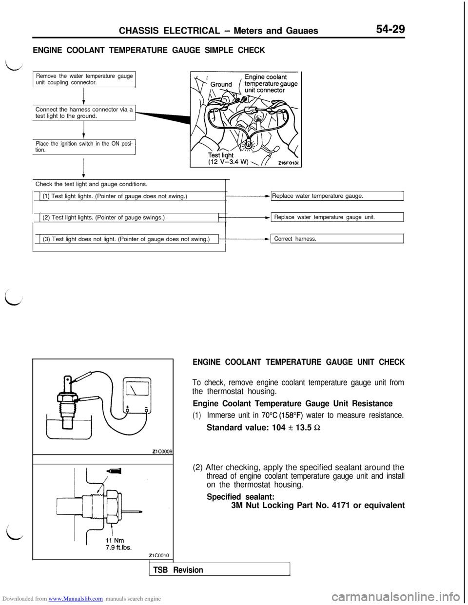
ENGINE COOLANT TEMPERATURE GAUGE SIMPLE CHECKConnect the harness connector via a
test light to the ground.
Remove the water temperature gauge
unit coupling connector.
t
Place the ignition switch in the ON posi-tion.
I
(12 v’3.4 w) \ //Z16FO13lCheck the test light and gauge conditions.
i(1) Test light lights. (Pointer of gauge does not swing.)_____c Replace water temperature gauge.
[ (2) Test light lights. (Pointer of gauge swings.)Replace water temperature gauge unit.
[ (3) Test light does not light. (Pointer of gauge does not swing.)/-------I Correct harness.
ENGINE COOLANT TEMPERATURE GAUGE UNIT CHECK
To check, remove engine coolant temperature gauge unit from
the thermostat housing.
Engine Coolant Temperature Gauge Unit Resistance
(1)Immerse unit in 70°C (158OF) water to measure resistance.Standard value: 104
f 13.5 Sz(2) After checking, apply the specified sealant around the
thread of engine coolant temperature gauge unit and install
on the thermostat housing.
Specified sealant:3M Nut Locking Part No. 4171 or equivalent
TSB RevisionI
Page 526 of 738
Downloaded from www.Manualslib.com manuals search engine 54-30CHASSIS ELECTRICAL - Meters and Gauges
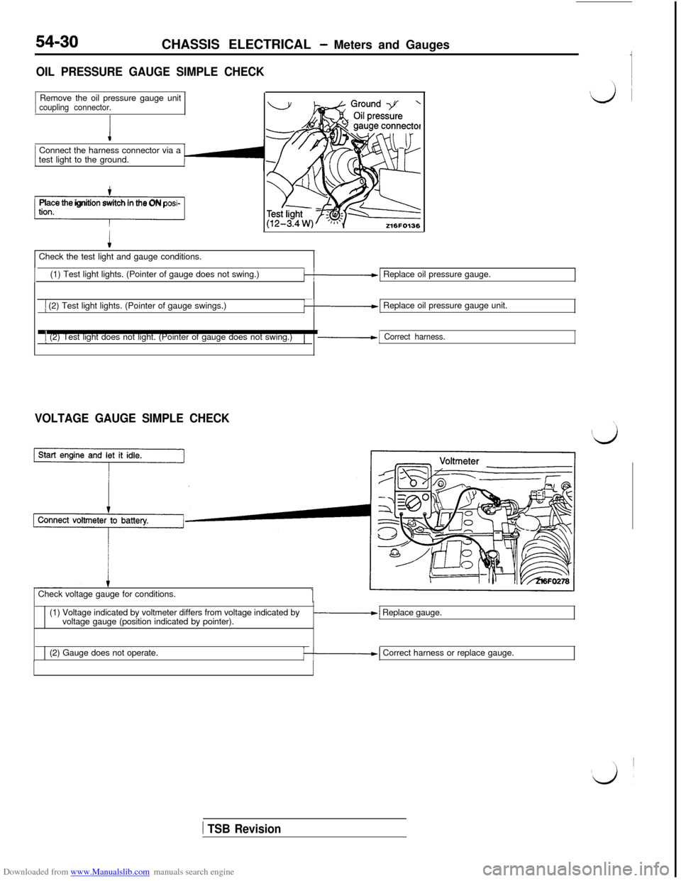
OIL PRESSURE GAUGE SIMPLE CHECKRemove the oil pressure gauge unit
coupling connector.Connect the harness connector via a
test light to the ground.
-1Place the ignition switch in the ON posi-Check the test light and gauge conditions.
(1) Test light lights. (Pointer of gauge does not swing.)
k-1 Replace oil pressure gauge.
1 (2) Test light lights. (Pointer of gauge swings.)k-1 Replace oil pressure gauge unit.
1 (2) Test light does not light. (Pointer of gauge does not swing.)/-1 Correct harness.
VOLTAGE GAUGE SIMPLE CHECKCheck voltage gauge for conditions.
(1) Voltage indicated by voltmeter differs from voltage indicated by
voltage gauge (position indicated by pointer).
-1 Replace gauge.
(2) Gauge does not operate.
/--I Correct harness or replace gauge.
1 TSB Revision
Page 528 of 738
Downloaded from www.Manualslib.com manuals search engine 54-32CHASSIS ELECTRICAL - Meters and Gauges
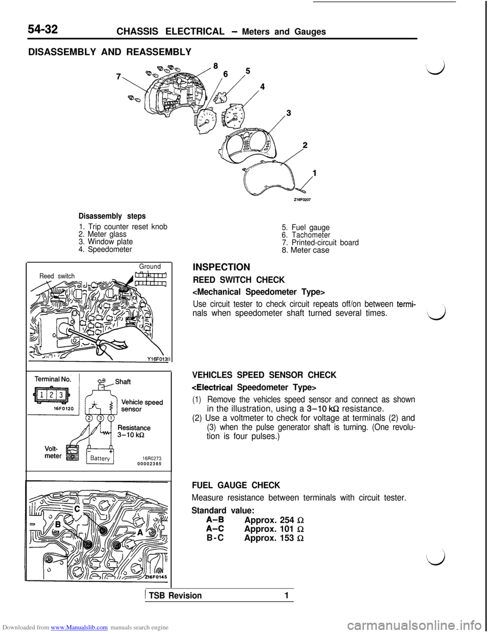
DISASSEMBLY AND REASSEMBLY
Disassembly steps
1. Trip counter reset knob
2. Meter glass
3. Window plate
4. Speedometer
Ground
Reed switch
16R027300002385
3
5. Fuel gauge6. Tachometer7. Printed-circuit board8. Meter case
INSPECTION
REED SWITCH CHECK
Use circuit tester to check circuit repeats off/on between termi-\
nals when speedometer shaft turned several times.d
VEHICLES SPEED SENSOR CHECK
(1)Remove the vehicles speed sensor and connect as shownin the illustration, using a
3-10 k&2 resistance.
(2) Use a voltmeter to check for voltage at terminals (2) and
(3) when the pulse generator shaft is turning. (One revolu-
tion is four pulses.)
FUEL GAUGE CHECK
Measure resistance between terminals with circuit tester.
Standard value:
;I;Approx. 254 0Approx. 101
I2B-C
Approx. 153
fi
1 TSB Revision1
Page 533 of 738
Downloaded from www.Manualslib.com manuals search engine CHASSIS ELECTRICAL - Lighting System54-37
i
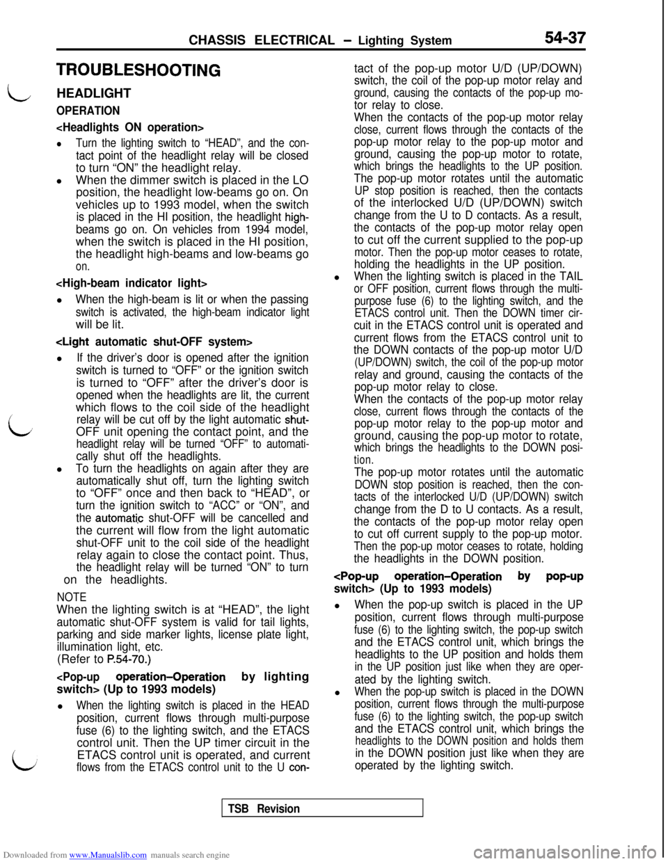
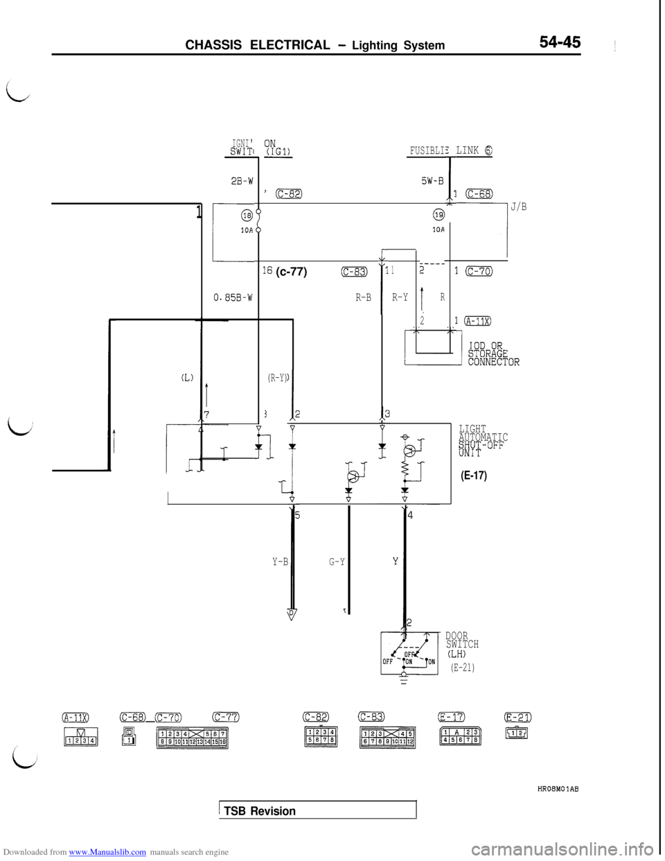
TROUBLESHOOTING
LHEADLIGHT
OPERATION
lTurn the lighting switch to “HEAD”, and the con-
tact point of the headlight relay will be closedto turn “ON” the headlight relay.
lWhen the dimmer switch is placed in the LO
position, the headlight low-beams go on. On
vehicles up to 1993 model, when the switch
is placed in the HI position, the headlight high-
beams go on. On vehicles from 1994 model,when the switch is placed in the HI position,
the headlight high-beams and low-beams go
on.
When the high-beam is lit or when the passing
switch is activated, the high-beam indicator lightwill be lit.
If the driver’s door is opened after the ignition
switch is turned to “OFF” or the ignition switchis turned to “OFF” after the driver’s door is
opened when the headlights are lit, the currentwhich flows to the coil side of the headlight
relay will be cut off by the light automatic shut-OFF unit opening the contact point, and the
headlight relay will be turned “OFF” to automati-
cally shut off the headlights.l
To turn the headlights on again after they are
automatically shut off, turn the lighting switchto “OFF” once and then back to “HEAD”, or
turn the ignition switch to “ACC” or “ON”, and
the
aut0mati.c shut-OFF will be cancelled andthe current will flow from the light automatic
shut-OFF unit to the coil side of the headlightrelay again to close the contact point. Thus,
the headlight relay will be turned “ON” to turnon the headlights.
NOTEWhen the lighting switch is at “HEAD”, the light
automatic shut-OFF system is valid for tail lights,
parking and side marker lights, license plate light,
illumination light, etc.(Refer to
P.54-70.)
l
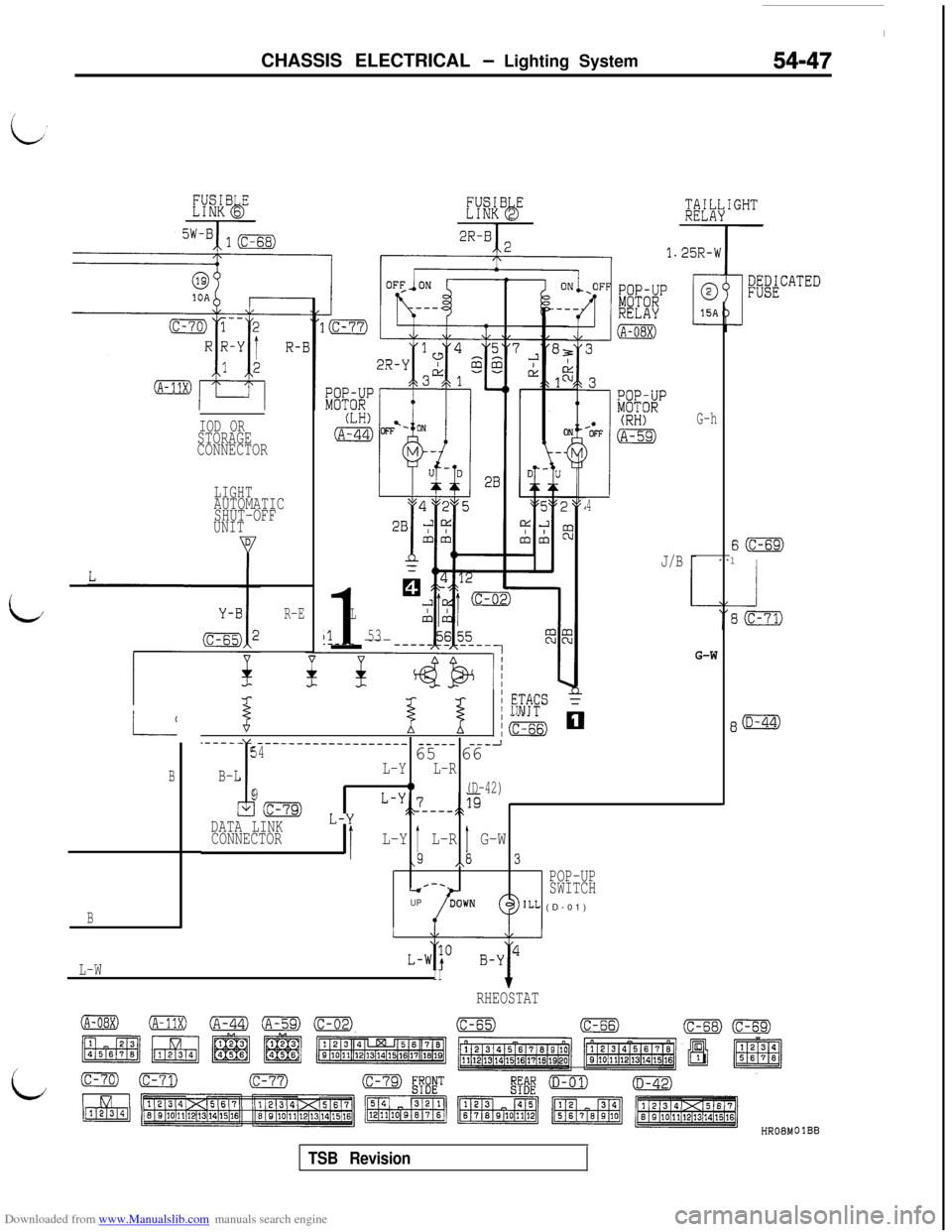
When the lighting switch is placed in the HEAD
position, current flows through multi-purpose
fuse (6) to the lighting switch, and the ETACScontrol unit. Then the UP timer circuit in the
LETACS control unit is operated, and currentflows from the ETACS control unit to the U con-tact of the pop-up motor U/D (UP/DOWN)
switch, the coil of the pop-up motor relay and
ground, causing the contacts of the pop-up mo-
tor relay to close.
When the contacts of the pop-up motor relay
close, current flows through the contacts of the
pop-up motor relay to the pop-up motor and
ground, causing the pop-up motor to rotate,
which brings the headlights to the UP position.
The pop-up motor rotates until the automatic
UP stop position is reached, then the contactsof the interlocked U/D (UP/DOWN) switch
change from the U to D contacts. As a result,
the contacts of the pop-up motor relay opento cut off the current supplied to the pop-up
motor. Then the pop-up motor ceases to rotate,
holding the headlights in the UP position.l
When the lighting switch is placed in the TAIL
or OFF position, current flows through the multi-
purpose fuse (6) to the lighting switch, and the
ETACS control unit. Then the DOWN timer cir-
cuit in the ETACS control unit is operated and
current flows from the ETACS control unit to
the DOWN contacts of the pop-up motor U/D
(UP/DOWN) switch, the coil of the pop-up motor
relay and ground, causing the contacts of the
pop-up motor relay to close.
When the contacts of the pop-up motor relay
close, current flows through the contacts of the
pop-up motor relay to the pop-up motor andground, causing the pop-up motor to rotate,
which brings the headlights to the DOWN posi-
tion.
The pop-up motor rotates until the automatic
DOWN stop position is reached, then the con-
tacts of the interlocked U/D (UP/DOWN) switch
change from the D to U contacts. As a result,
the contacts of the pop-up motor relay open
to cut off current supply to the pop-up motor.
Then the pop-up motor ceases to rotate, holding
the headlights in the DOWN position.
When the pop-up switch is placed in the UP
position, current flows through multi-purpose
fuse (6) to the lighting switch, the pop-up switch
and the ETACS control unit, which brings the
headlights to the UP position and holds them
in the UP position just like when they are oper-
ated by the lighting switch.l
When the pop-up switch is placed in the DOWN
position, current flows through the multi-purpose
fuse (6) to the lighting switch, the pop-up switch
and the ETACS control unit, which brings the
headlights to the DOWN position and holds them
in the DOWN position just like when they are
operated by the lighting switch.
TSB Revision
Page 534 of 738
Downloaded from www.Manualslib.com manuals search engine CHASSIS ELECTRICAL - Liahting System
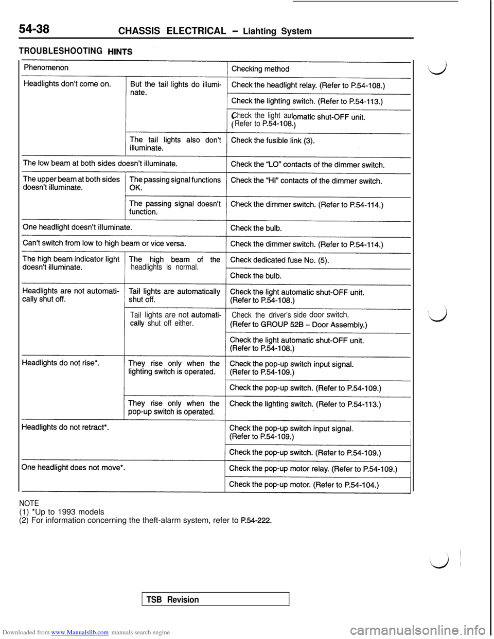
TROUBLESHOOTING
Check the light aut
Refer to
P.54-108.
headlights is normal.
Taillights are not automati-
Check the driver’ssidedoor switch.tally
shut off either.
NOTE(1) *Up to 1993 models
(2) For information concerning the theft-alarm system, refer to
P.54-222.
TSB Revision
Page 537 of 738
Downloaded from www.Manualslib.com manuals search engine CHASSIS ELECTRICAL - Lighting System54-41
(L
1
IGNI'ISWITC
2B-rh(c-77)
0.85B-t
16(c-83)
R-B
0.85B-W
R-B
73
T
bJ-
1
Y
FUSIBLE LINK@I5W-B
J/B
G-Y
I----11 2
R-Y R
c
T
2
3
-
'4
.2 (E-21)@SWITCH
(E-17)(E-21)
1
(A-11X)
IOD ORSTORAGE
CONNECTOR
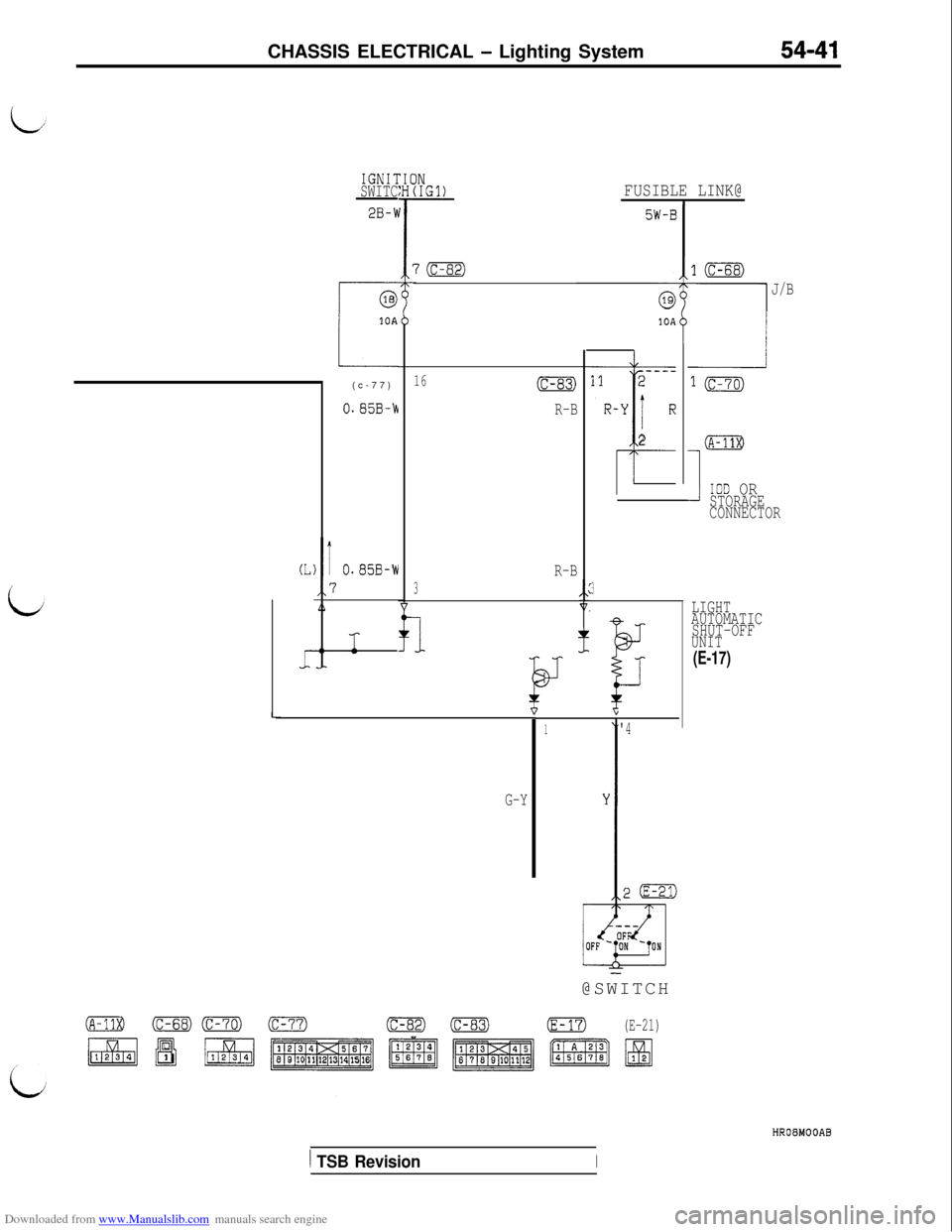
LIGHT
AUTOMATIC
SHUT-OFF
UNIT
(E-17)
HROEMOOAB
1 TSB RevisionI
Page 538 of 738
Downloaded from www.Manualslib.com manuals search engine 54-42CHASSIS ELECTRICAL - Lighting System
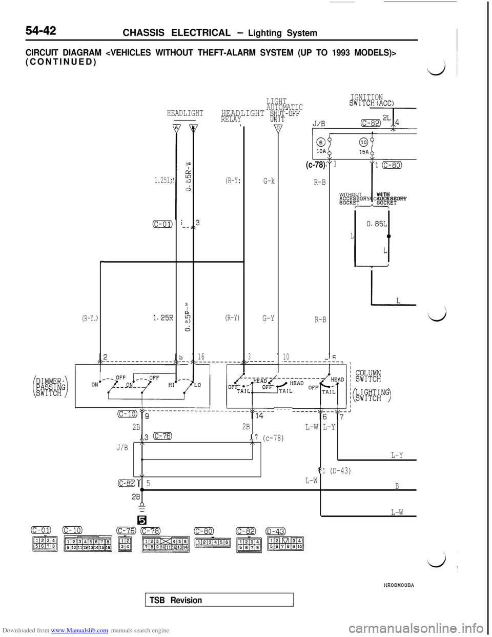
CIRCUIT DIAGRAM
(R-Y.
HEADLIGHT
1.251;
(c-01)j-_,\
L
c
)1.25R
B3
EI
z:aJ
C5
LIGHTIGNITION
AUTOMATICSWITCH(ACC)
HEADLIGHT gWi-i;-OFFRELAY7,J/B -7
(R-Y:I
@0
10A15AY(c-78)\I:3
G-k
R-BWITHOUTP.~~“.~~ORY
-3
I
P;
a(R-Y)G-YR-B
i;3
16310.-_.------.-----------
7 r
-__-7
(c-01)
l(c-80)
iWITH
ACCESSORY*ET
m&c-----------------------~q-6-- ---- ------""s--"F-'
2B2BL-W L-Y
,,3 mx.7 (c-78)
J/B/\I\
t.L-Y
\/St1 (D-43)
(c-82)“ 5L-W
0B28n
0
L-W
HROEMOOBA
TSB Revision
Page 541 of 738
Downloaded from www.Manualslib.com manuals search engine CHASSIS ELECTRICAL - Lighting System54-45 ~
IGNI'SWITl
2B-W
@
i10A
O.S5B-W
LINK 8FUSIBLI
5W-B
'c3B
1
7
J/B@
10A
-----2
I,R
2
1
i
16 (c-77)(c-83)1
R-Y
l(c-70)
10
R-B
(L)(R-Y)
3
1
-II.
13-
;
LIGHT
AUTOMATIC
##F-OFF
(E-17)
G-Y
I
(c-82)
Y-B
DOOR
SWITCH
(LH)
(E-21)
(c-68) Gz=m)(c-77)
/EJp&p$zgy
HRO8MOlAB
1 TSB Revision
Page 543 of 738
Downloaded from www.Manualslib.com manuals search engine CHASSIS ELECTRICAL - Lighting System54-47
G-hIOD ORSTORAGE
CONNECTOR
LIGHTAUTOMATIC
SHUT-OFF
UNIT
4
J/B
S(c-69)1
1
L
1153.---- ---
/R-E
G-W
%I 1
/ #FS
/m mL-L
B
.----- ____________------_
Ii
----- ---J5465 66
B-LL-YL-R
90(D-42)
Ic-79) L-y L-y:;_7_--+p
DATA LINK
CONNECTOR1L-Y b L-R 1, G-W 3
\/\POP-UPr-.-sSWITCHUPILL (D-01)B
L-WII+RHEOSTAT
/
id
OlBB
TSB Revision