Assembly MITSUBISHI 3000GT 1995 2.G Owner's Manual
[x] Cancel search | Manufacturer: MITSUBISHI, Model Year: 1995, Model line: 3000GT, Model: MITSUBISHI 3000GT 1995 2.GPages: 738, PDF Size: 35.06 MB
Page 375 of 738
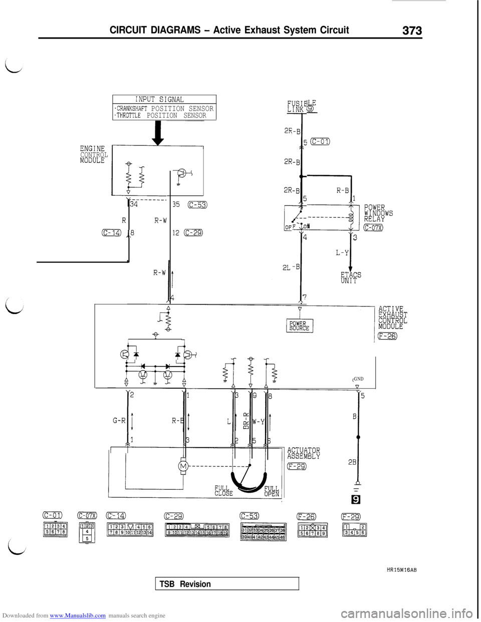
Downloaded from www.Manualslib.com manuals search engine CIRCUIT DIAGRAMS - Active Exhaust System Circuit373
ENGINE
CONTROL
MODULE
INPUT SIGNAL
.CRANKSHAFT POSITION SENSOR.THROTTLE POSITION SENSOR
RR-W
(c- ,,8
F
35 (c-53)
12 (c-29)
2R
2R
2R
I
@I-+ f
2
G-R
IIR-B
r-k-
F- 01
4
T
-B
7
bjgE-
‘(c-01)
R-B1
3
POWERWINDOWS-____---_RELAYN(c-07x)
3
L-Y
KkF"
GND
5
ACTUATORASSEMBLY
lEgI
B
i
2B
(c-01)o(c’14)m(c-53)(F-26)HRlSMlGAB
TSB Revision
Page 418 of 738
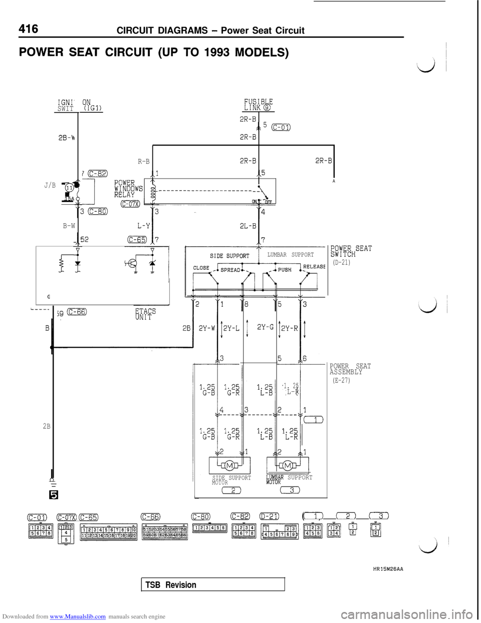
Downloaded from www.Manualslib.com manuals search engine 416CIRCUIT DIAGRAMS - Power Seat Circuit
POWER SEAT CIRCUIT (UP TO 1993 MODELS)
IGNI'SWIT
2B-k
J/Br
0
15A
B-W
i-
G
2B
ON(IGl)E%B9Eb
2R-B
:k5 (c-01)
2R-B
R-B2R-B2R-B
7m,,l,,5
IA
-------__-___----------
32
LUMBAR SUPPORT
jg (c-66)
0
I2Y-G
1. 25L-R
SIDE SUPPORTMOTOR"MJJyi;R SUPPORT
aCD#;$HSEAT
(D-21)
POWER SEAT
ASSEMBLY
(E-27)
(c-01)(rn(c-65)(c-66)(c-80)(C-82)0(E-27)(1) cz-) c-T-1
~1~~~1~~~~~9 @
HR15M26AA
TSB Revision
Page 420 of 738
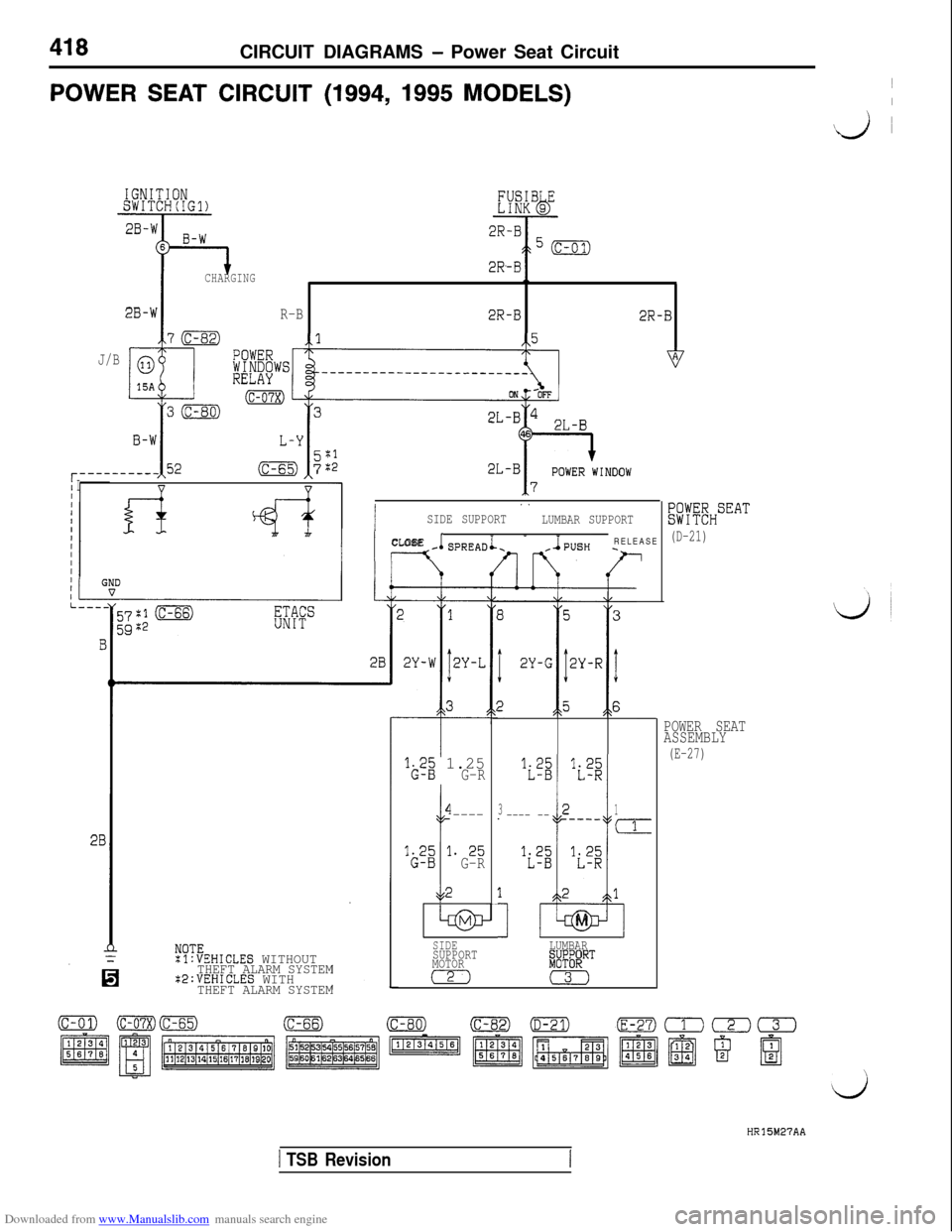
Downloaded from www.Manualslib.com manuals search engine 418CIRCUIT DIAGRAMS - Power Seat Circuit
POWER SEAT CIRCUIT (1994, 1995 MODELS)1I
\j i
CHARGING1.
2B-WR-B2R-B2R-B
70,l-5
J/B
r----/ Ivv
B
28
NOTE
0
:l:VEHICLES WITHOUTTHEFT ALARM SYSTEM:2:VEHICLES WITHTHEFT ALARM SYSTEM
I
. .
SIDE SUPPORT
LUMBAR SUPPORT
I IL’CLOSE- SPREADiRELEASE--h
‘G.2; 1.25G-R
I
4----
‘22 l. 25G-R
li’Z ‘i’g
32
I-i
1_ ---- ---___m
‘i’s ‘is;
121
u!z!lM
SIDELUMBAR
SUPPORT
MOTOR$JF@RT
m0
Kl:fEHSEAT
(D-21)
POWER SEAT
ASSEMBLY
(E-27)
HR15M27AA
1 TSB Revision
Page 422 of 738
Downloaded from www.Manualslib.com manuals search engine 420
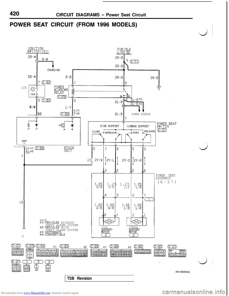
CIRCUIT DIAGRAMS - Power Seat Circuit
POWER SEAT CIRCUIT (FROM 1996 MODELS)
70
015A
t
30
B-W
__--- 52
J/B
- T32L-Bw
I
TV2L-BPOWER WINDOW
GNDV
.,I-----
l
57:10
5Qx2RF"
B
iL
2
t2B 2Y-\NI
'i'$
2--,,1,
'i'2
2$$l
POWER SEAT
ASSEMBLY(E-27)
1.25 1.25
G-RL-E
2B
!
NOTEXl:VEHICLES WITHOUTTHEFT ALARM SYSTEMZ2:VEHICLES WITH6THEFT ALARM SYSTEM:3:HATCHBACKX4:CONVERTIBLE
SIDE
LUMBAR
aRiRT&J;'RT
1'2)0L
HR15M38AA
TSB Revision
Page 429 of 738
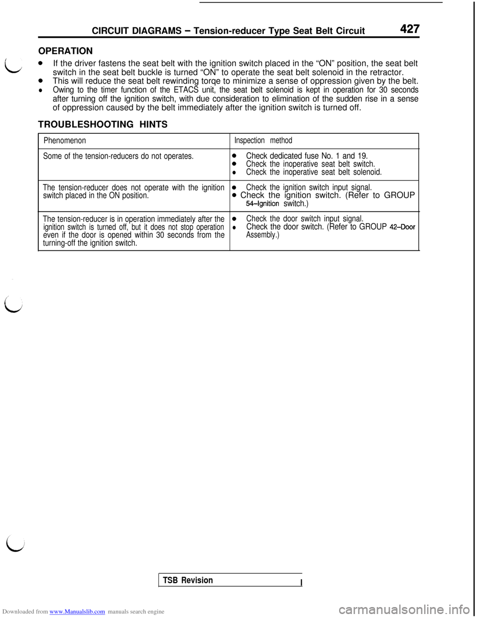
Downloaded from www.Manualslib.com manuals search engine CIRCUIT DIAGRAMS - Tension-reducer Type Seat Belt Circuit427OPERATION
L0If the driver fastens the seat belt with the ignition switch placed in the “ON” position, the seat belt
switch in the seat belt buckle is turned “ON” to operate the seat belt solenoid in the retractor.
0This will reduce the seat belt rewinding torqe to minimize a sense of oppression given by the belt.
lOwing to the timer function of the ETACS unit, the seat belt solenoid is kept in operation for 30 seconds
after turning off the ignition switch, with due consideration to elimination of the sudden rise in a senseof oppression caused by the belt immediately after the ignition switch is turned off.
TROUBLESHOOTING HINTS
PhenomenonInspection method
Some of the tension-reducers do not operates.0Check dedicated fuse No. 1 and 19.
0Check the inoperative seat belt switch.
lCheck the inoperative seat belt solenoid.
The tension-reducer does not operate with the ignition
0Check the ignition switch input signal.
switch placed in the ON position.
0 Check the ignition switch. (Refer to GROUP
M-Ignition switch.)
The tension-reducer is in operation immediately after the0Check the door switch input signal.
ignition switch is turned off, but it does not stop operationlCheck the door switch. (Refer to GROUP 42-Door
even if the door is opened within 30 seconds from theAssembly.)
turning-off the ignition switch.
TSB Revision
I
Page 458 of 738
Downloaded from www.Manualslib.com manuals search engine 16-12ENGINE ELECTRICAL - Charging System
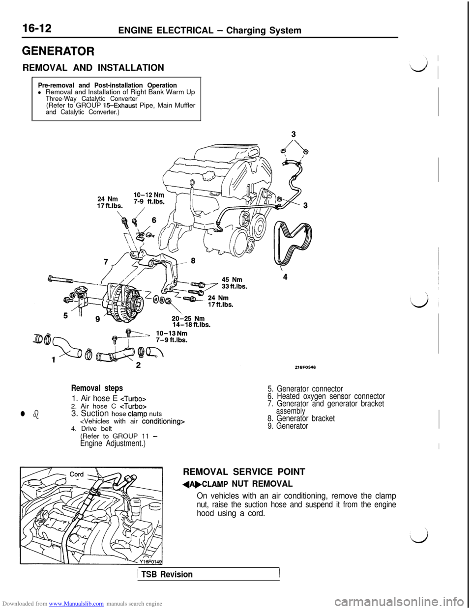
GENERATORREMOVAL AND INSTALLATION
Pre-removal and Post-installation Operationl Removal and Installation of Right Bank Warm Up
Three-Way Catalytic Converter(Refer to GROUP 15-Exhaust Pipe, Main Mufflerand Catalytic Converter.)14-18ft.lbs.
l b
Removal steps
1. Air hose E
3. Suction hose clamo nuts
(Refer to GROUP 11
-Engine Adjustment.)
216FO346
5. Generator connector
6. Heated oxygen sensor connector
7. Generator and generator bracket
assembly8. Generator bracket
9. Generator
lo-12 Nm7-9 ft.lbs.24 NmREMOVAL SERVICE POINT
dAbCLAMP NUT REMOVAL
On vehicles with an air conditioning, remove the clamp
nut, raise the suction hose and suspend it from the engine
hood using a cord.
1 TSB Revision
Page 459 of 738

Downloaded from www.Manualslib.com manuals search engine ENGINE ELECTRICAL - Charging System16-13DISASSEMBLY AND REASSEMBLY
i(Up to 1995 models)23I
LDisassembly steps
4A,1. Generator pulley.A+ 2. Rotor assembly3.Rear bearing4.Bearing retainer5.Front bearing6.Front bracket4B,7.Stator8. Insulator
9. Plate
10. Reaulator and brush holder
11.
Slinlger12. Rectifier13. Brush14. Brush spring
15. Rear bracket
4B,27EL0104
1 TSB Revision
Page 460 of 738
Downloaded from www.Manualslib.com manuals search engine 16-14ENGINE ELECTRICAL - Charging System
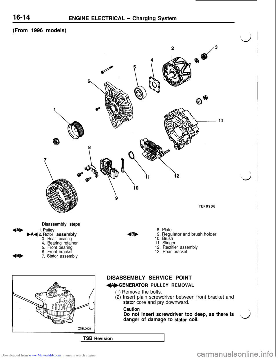
(From 1996 models)
Disassembly steps
+A,,A+ :: ~%? assembly3.Rear bearing4.Bearing retainer5.Front bearing6.Front bracket
45,7.Stator assembly
13
TEN0906
8. Plate9. Regulator and brush holder
10. Brush
11. Slinger
12. Rectifier assembly
13. Rear bracket
IDISASSEMBLY SERVICE POINT
dAbGENERATOR PULLEY REMOVAL
(1) Remove the bolts.
(2) Insert plain screwdriver between front bracket and
stator core and pry downward.
Caution
Do not insert screwdriver too deep, as there is
danger of damage to
stator coil.
TSB Revision
Page 461 of 738
Downloaded from www.Manualslib.com manuals search engine ENGINE ELECTRICAL - Charging System16-15
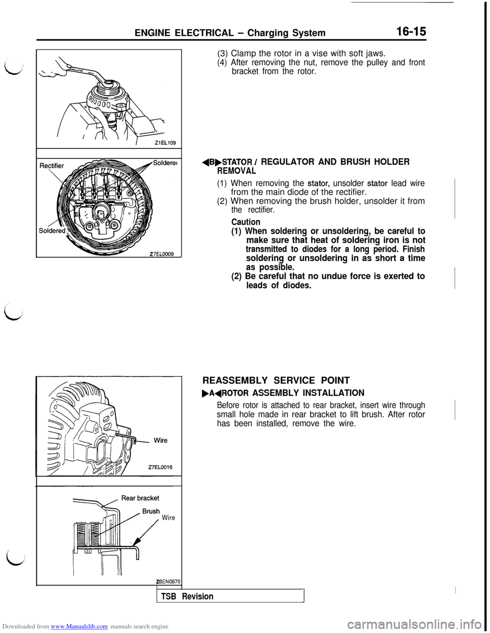
WireZ6EN087!(3) Clamp the rotor in a vise with soft jaws.
(4) After removing the nut, remove the pulley and front
bracket from the rotor.
AB,STATOR / REGULATOR AND BRUSH HOLDER
REMOVAL
(1) When removing the stator, unsolder stator lead wirefrom the main diode of the rectifier.
(2) When removing the brush holder, unsolder it from
the rectifier.
Caution
(1) When soldering or unsoldering, be careful to
make sure that heat of soldering iron is not
transmitted to diodes for a long period. Finish
soldering or unsoldering in as short a time
as possible.
(2) Be careful that no undue force is exerted to
leads of diodes.REASSEMBLY SERVICE POINT
FAdROTOR ASSEMBLY INSTALLATION
Before rotor is attached to rear bracket, insert wire through
small hole made in rear bracket to lift brush. After rotor
has been installed, remove the wire.
3
TSB RevisionI
I
Page 462 of 738
Downloaded from www.Manualslib.com manuals search engine ENGINE ELECTRICAL - Charging System
h\Z3ELOlO
\23ELOllINSPECTION
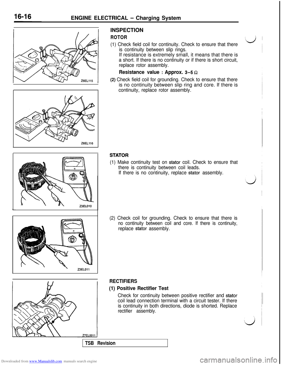
ROTOR
(1) Check field coil for continuity. Check to ensure that there
is continuity between slip rings.If resistance is extremely small, it means that there is
a short. If there is no continuity or if there is short circuit,
replace rotor assembly.
Resistance value : Approx. 3-5 Q
(2) Check field coil for grounding. Check to ensure that thereis no continuity between slip ring and core. If there is
continuity, replace rotor assembly.
STATOR
(1) Make continuity test on stator coil. Check to ensure that
there is continuity between coil leads.
If there is no continuity, replace
stator assembly.
(2) Check coil for grounding. Check to ensure that there is
no continuity between coil and core. If there is continuity,
replace stator assembly.
RECTIFIERS
(1) Positive Rectifier Test
Check for continuity between positive rectifier and stator
coil lead connection terminal with a circuit tester. If there
is continuity in both directions, diode is shorted. Replace
rectifier assembly.
TSB Revision