Assembly MITSUBISHI 3000GT 1995 2.G Service Manual
[x] Cancel search | Manufacturer: MITSUBISHI, Model Year: 1995, Model line: 3000GT, Model: MITSUBISHI 3000GT 1995 2.GPages: 738, PDF Size: 35.06 MB
Page 566 of 738
Downloaded from www.Manualslib.com manuals search engine 54-70CHASSIS ELECTRICAL - Lighting System
OPERATION
0When the lighting switch is placed in the TAILor HEAD position, current flows through the
coil of the tail light relay to the lighting switchand ground, causing the contacts of the tail
light relay to close.
Then current flows through the contacts of thetail light relay to the dedicated fuse
(2) the
individual lights and ground, causing the tail
lights, parking/side marker lights and licenseplate lights to go ON.
lIf the driver’s door is opened after the ignition
switch is turned to “OFF” or the ignition switchis turned to “OFF” after the driver’s door is
opened when the tail lights are lit, the current
which flows to the coil side of the tail light relaywill be cut off by the light automatic shut-off
unit opening the contact point, and the tail light
relay will be turned “OFF’ to automatically shut
off the tail lights, parking and front side marker
lights and license plate light.
lTo turn on the tail lights, parking and front side
marker lights and license plate light again after
they are automatically shut off, turn the lightingswitch to “OFF” once and to “HEAD” again,
or turn the ignition switch to “ACC” or “ON”,
and the automatic shut-OFF will be cancelled
and the current will flow from the light automaticshut-OFF unit to the coil side of the tail light
relay to close the contact point. Thus, the taillight relay will be turned “ON” to turn on the
tail lights, parking and front marker lights and
license plate light.
NOTE
When the lighting switch is at the “HEAD” position,
the light automatic shut-OFF system will be also
activated for the headlights. (Refer to P.54-37.) The
same system will also be activated for the illumina-
tion lights, etc.
TROUBLESHOOTING HINTS1. All lights don’t illuminate.
(1) The headlights don’t illuminate, either.l Check the fusible link (3).
(2) The headlights illuminate.l Check the tail light relay. (Refer to
P.54-108.)l Check the dedicated fuse (2).
l Check the lighting switch. (Refer to
P.54-113.)l Check the light automatic shut-OFF
unit. (Refer to
P.54-108.)2. Some light does not come on.
l Check the bulb.
l Check the grounding circuit.
3. Some light is not automatically shut off.
lCheck the driver’s side door switch.
(Refer to GROUP 42- Door Assembly.)l Check the automatic shut-OFF unit.
(Refer to
P.54-108.)
1 TSB Revision
Page 593 of 738
Downloaded from www.Manualslib.com manuals search engine CHASSIS ELECTRICAL - Lighting System54-97
COLUMN SWITCH
iCARBURETTOR
ASSEMBLY1
(G-L(LG-E
0.85G-L
0.85G-L
(c-02)
0.85G-L
L-----_
(LG-R
;5
2B
(D-41)
2E13
101m
I)
34
1.
,4
2B
nz
0.8EG-F
0.85G-R
------
0.85
LG-R
0.85G-L0.85G-f
,J3--------------19
0.85G-Lx10.85GR-IGR-L*2
r-y3I /
wCOMBINATION B4LIGHT (LH)
(F-30) 2B
!
1
COMBINATION
12m
3
TSB Revision
Page 599 of 738
Downloaded from www.Manualslib.com manuals search engine HEADLIGHT
CHASSIS ELECTRICAL - Lighting System54-103
REMOVAL AND INSTALLATION
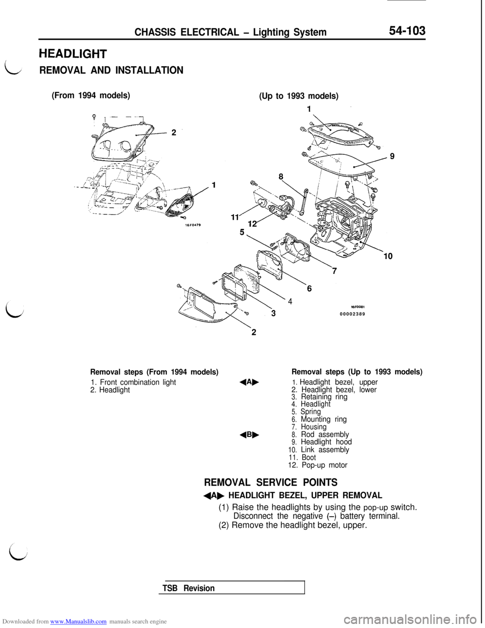
(From 1994 models)
(Up to 1993 models)
Removal steps (From 1994 models)
1. Front combination light
2. Headlight
4Bb
4WFOOB100002389
Removal steps (Up to 1993 models)
1. Headlight bezel, upper
2. Headlight bezel, lower
3.Retaining ring4.Headlight5.Spring6.Mounting ring7.Housing8.Rod assembly9.Headlight hood
10.Link assembly11. Boot12. Pop-up motor
REMOVAL SERVICE POINTS
+A, HEADLIGHT BEZEL, UPPER REMOVAL(1) Raise the headlights by using the pop-up switch.
Disconnect the negative (-) battery terminal.(2) Remove the headlight bezel, upper.
TSB Revision
Page 600 of 738
Downloaded from www.Manualslib.com manuals search engine CHASSIS ELECTRICAL - Lighting System
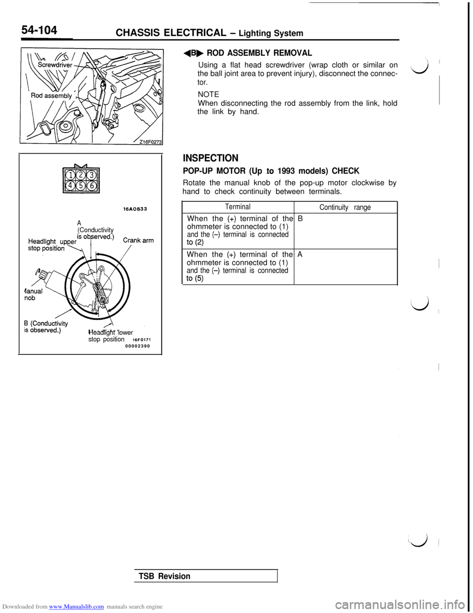
16A0833
A(Conductivity
Headlight lower
stop position
16FO17100002390
+B, ROD ASSEMBLY REMOVALUsing a flat head screwdriver (wrap cloth or similar on
the ball joint area to prevent injury), disconnect the connec-
tor.NOTE
When disconnecting the rod assembly from the link, hold
the link by hand.
INSPECTION
POP-UP MOTOR (Up lo 1993 models) CHECKRotate the manual knob of the pop-up motor clockwise by
hand to check continuity between terminals.
TerminalWhen the
(+) terminal of the B
ohmmeter is connected to (1)
and the (-) terminal is connected
to (2)
Continuity rangeWhen the
(+) terminal of the A
ohmmeter is connected to (1)
and the (-) terminal is connected
to (5)
‘1 I
Lj
I
‘d ~~
iji
TSB Revision
Page 601 of 738
Downloaded from www.Manualslib.com manuals search engine CHASSIS ELECTRICAL - Lighting System54-105FOG LIGHT
REMOVAL AND INSTALLATION
(Up to 1993 models)
,’
..-.-f .- . . .._ 1’yI’-’--.._ . . . ./’‘._,/‘.:‘. . . . . .--ye=.,/‘c’ !:I’:.;; ____-... _.__-.-__~___. . . . . ._./i L.- -3...-.._:.y- .‘...-____ y--. . . . . --‘-T---..-_ -_--._ _ __.-.-.;.? ::.._/ ; .--_.‘7 ,,-y-? ..-,r-; ‘;
‘....lr/I..j ,/L7 rl,-’/I” . . . ..-. ~ -,-.-A:..____ p
A’7----p--*@
,,A..
*~~~~1;’ -“‘.,.
, ‘!U ,.I,/ Ii
8, $&$Jqk2&
4&;. +I+ ’
,,, ’ .’- ‘-I,i
4!a
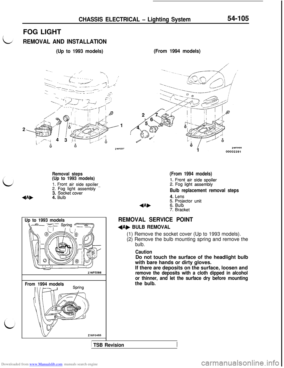
Removal steps(Up to 1993 models)
1. Front air side spoiler2. Fog light assembly -3. Socket cover4. Bulb
Up to 1993 models
Z16FO268
From1994 models
wZl6FO465
(From 1994 models)
(From 1994 models)
1. Front air side spoiler2. Fog light assembly
Bulb replacement removal steps4.
Lens5. Projector unit6. Bulb7. Bracket
REMOVAL SERVICE POINT
+A, BULB REMOVAL(1) Remove the socket cover (Up to 1993 models).
(2) Remove the bulb mounting spring and remove the
bulb.
CautionDo not touch the surface of the headlight bulb
with bare hands or dirty gloves.
If there are deposits on the surface, loosen and
remove the deposits with a cloth dipped in alcohol
or thinner, and let the surface dry before mounting
the bulb.
1 TSB Revision
Page 602 of 738
Downloaded from www.Manualslib.com manuals search engine 54-106CHASSIS ELECTRICAL - Lighting SystemFRONT COMBINATION LIGHT AND OPTICAL HORN LENS
REMOVAL AND INSTALLATION(Up to 1993 models)
j&z?&/ optica’ horn Iens
(From 1994 models)
L.JZ16FO216Z16FO47600002392
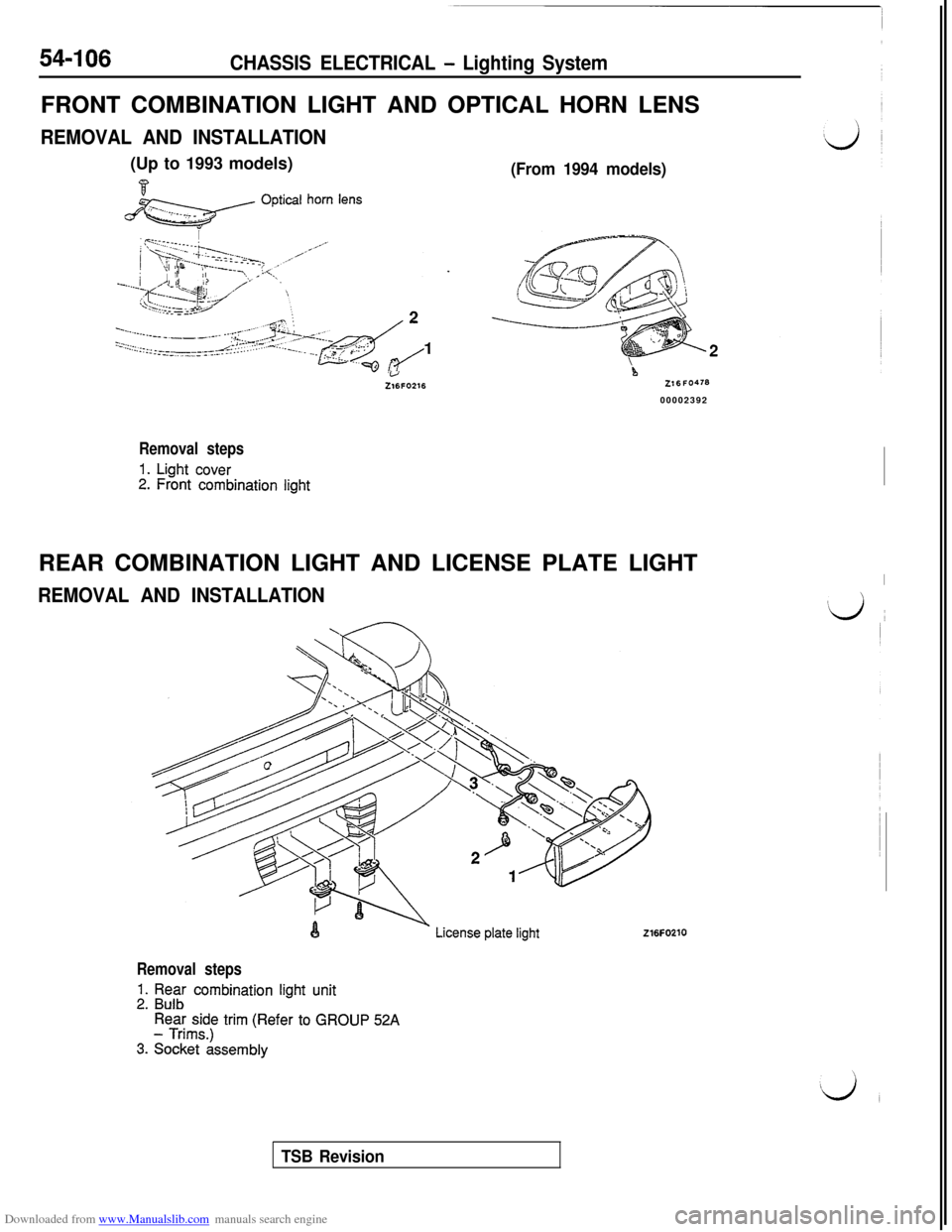
Removal steps
1. Light cover2. Front combination lightREAR COMBINATION LIGHT AND LICENSE PLATE LIGHT
REMOVAL AND INSTALLATION
I
#d ~
216FO210
Removal steps
1. Rear combination light unit2. Bulb
Rear side trim (Refer to GROUP 52A- Trims.)
3. Socket assembly
TSB Revision
Page 603 of 738
Downloaded from www.Manualslib.com manuals search engine CHASSIS ELECTRICAL - Lighting SystemHIGH MOUNTED STOP LIGHT
REMOVAL AND INSTALLATION
Z 16FO229Z 16FO229
‘\ \/4
116FcJ23100002393 00002393
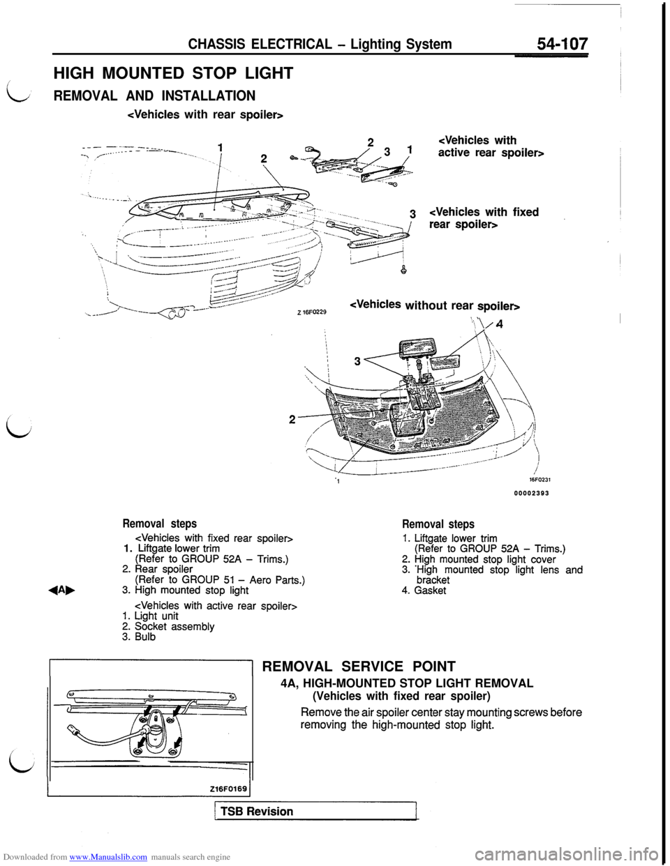
Removal steps
Removal steps
1. Liftgate lower trim(Refer to GROUP 52A - Trims.)2. High mounted stop light cover3. ;;z;keyounted stop light lens and
4. Gasket
&I REMOVAL SERVICE POINT
4A, HIGH-MOUNTED STOP LIGHT REMOVAL
(Vehicles with fixed rear spoiler)
Remove the air spoiler center stay mounting screws beforeremoving the high-mounted stop
light.
Page 606 of 738
Downloaded from www.Manualslib.com manuals search engine 54-110CHASSIS ELECTRICAL - Lighting System
1
16FO121
16FO12600002396
I‘VA1 I\ Air outlet assembly _I
RHEOSTAT\
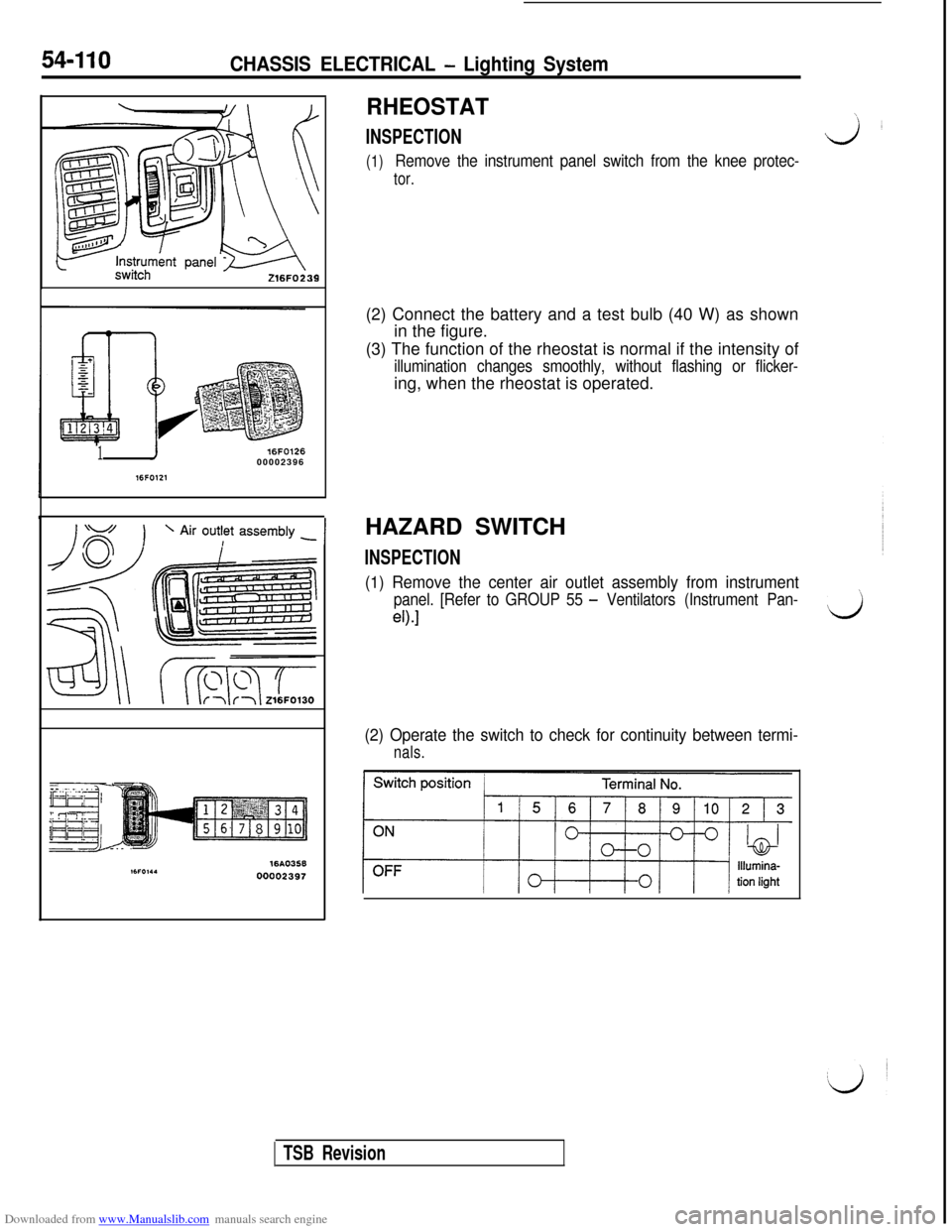
INSPECTIONJL
(1)Remove the instrument panel switch from the knee protec-
tor.(2) Connect the battery and a test bulb (40 W) as shown
in the figure.
(3) The function of the rheostat is normal if the intensity of
illumination changes smoothly, without flashing or flicker-ing, when the rheostat is operated.
HAZARD SWITCH
INSPECTION
(1) Remove the center air outlet assembly from instrument
panel. [Refer to GROUP 55 - Ventilators (Instrument Pan-’
eO.1d
(2) Operate the switch to check for continuity between termi-
nals.
TSB Revision
Page 614 of 738
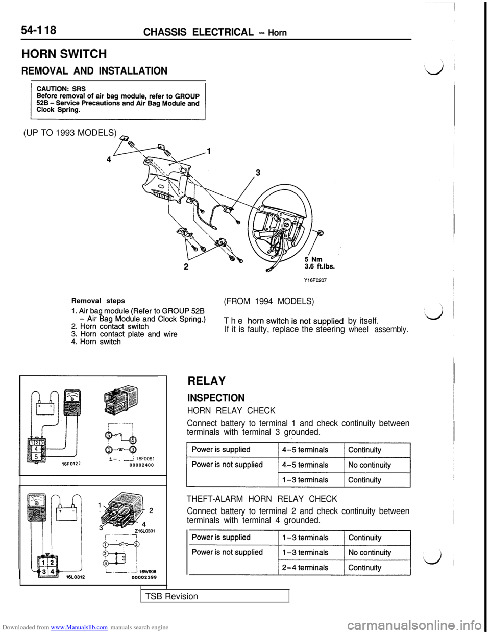
Downloaded from www.Manualslib.com manuals search engine 54-I 18CHASSIS ELECTRICAL - HornHORN SWITCH
REMOVAL AND INSTALLATION(UP TO 1993 MODELS)
~
Y16FO207Removal steps
1. Air bag module (Refer to GROUP 528
(FROM 1994 MODELS)
- Air Bag Module and Clock Spring.)2. Horn contact switch3. Horn contact plate and wire4. Horn switchThe
horn switch is not supplied
If it is faulty, replace the steeringby itself.wheel assembly.i-.
-L 16FOO61200002400
RELAY
INSPECTION
HORN RELAY CHECK
Connect battery to terminal 1 and check continuity between
terminals with terminal 3 grounded.
~1
THEFT-ALARM HORN RELAY CHECK
Connect battery to terminal 2 and check continuity between
terminals with terminal 4 grounded.TSB Revision
Page 678 of 738
Downloaded from www.Manualslib.com manuals search engine 54-182CHASSIS ELECTRICAL - Radio and Tape Player
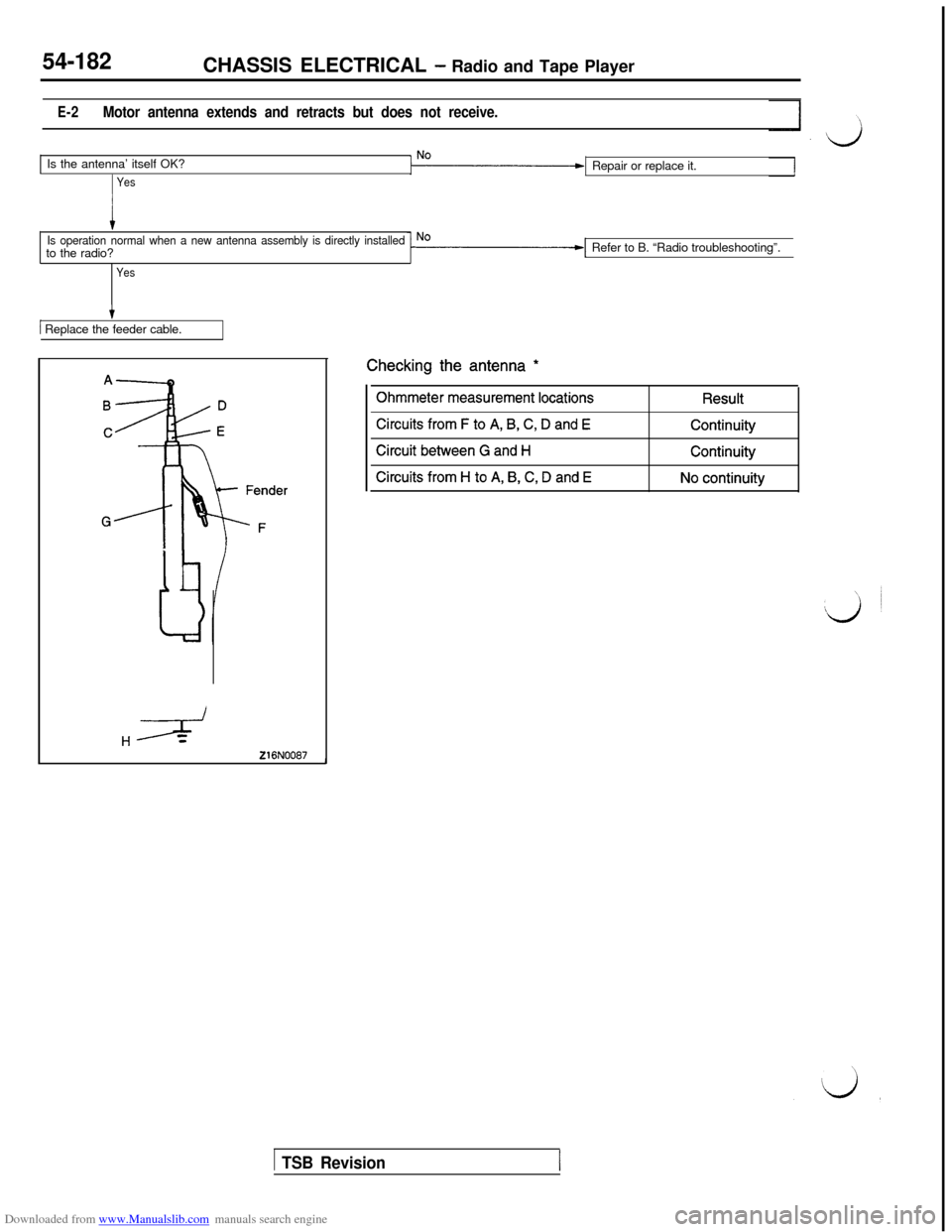
E-2Motor antenna extends and retracts but does not receive.Is the antenna’ itself OK?
YesRepair or replace it.
Is operation normal when a new antenna assembly is directly installedto the radio?
YesRefer to B. “Radio troubleshooting”.
/ Replace the feeder cable.
Hz+
216N0087-IChecking the antenna
*
Ohmmeter measurement locations
Circuits from F to A, B, C, D and E
Circuit between G and H
Circuits from H to A, B, C, D and E
Result
Continuity
Continuity
No continuity
1 TSB Revision