Assembly MITSUBISHI 3000GT 1995 2.G Owner's Guide
[x] Cancel search | Manufacturer: MITSUBISHI, Model Year: 1995, Model line: 3000GT, Model: MITSUBISHI 3000GT 1995 2.GPages: 738, PDF Size: 35.06 MB
Page 463 of 738
Downloaded from www.Manualslib.com manuals search engine ENGINE ELECTRICAL - Charging System16-17
Limit line
WELO
,Soldered
27EL0014
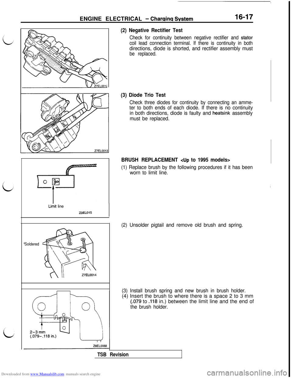
(2) Negative Rectifier Test
Check for continuity between negative rectifier and stator
coil lead connection terminal. If there is continuity in both
directions, diode is shorted, and rectifier assembly must
be replaced.
(3) Diode Trio Test
Check three diodes for continuity by connecting an amme-
ter to both ends of each diode. If there is no continuity
in both directions, diode is faulty and
heatsink assembly
must be replaced.
BRUSH REPLACEMENT
(1) Replace brush by the following procedures if it has been
worn to limit line.
(2) Unsolder pigtail and remove old brush and spring.
(3) Install brush spring and new brush in brush holder.(4) Insert the brush to where there is a space 2 to 3 mm
(.079 to .118 in.) between the limit line and the end of
the brush holder.
TSB Revision
Page 472 of 738
Downloaded from www.Manualslib.com manuals search engine 16-26ENGINE ELECTRICAL - Starting System
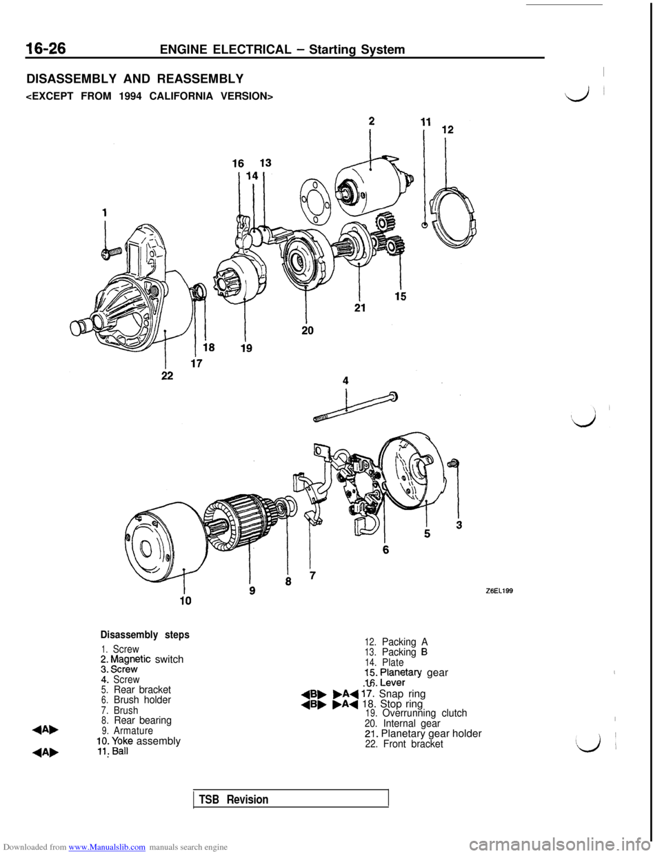
DISASSEMBLY AND REASSEMBLY
I
Lj~
Disassembly steps
1.Screw;. f$gnntic switch
4:Screw5.Rear bracket6.Brush holder7.Brush8.Rear bearing
4Ab9.Armature;;. paF assembly
4A, .
12.Packing A13.Packing B14.Plate=I:. ;an$ary gear
+B, .A+ 17: Snap ring4B, .A+ 18. Stop ring19.Overrunning clutch20.Internal gear21. Planetary gear holder22.Front bracket
,
I!Lj
’
TSB Revision
Page 473 of 738
Downloaded from www.Manualslib.com manuals search engine ENGINE ELECTRICAL - Starting System16-27
27EN0628
1'0
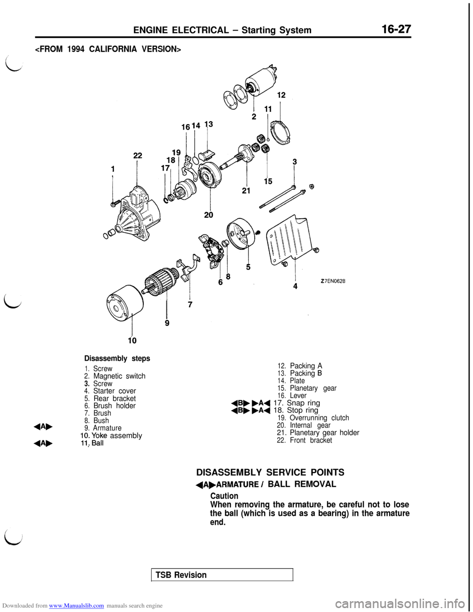
Disassembly steps
1.Screw2.Magnetic switch3.Screw4.Starter cover5.Rear bracket6.Brush holder7.Brush8.Bush4A,9.Armature;y. Fap assembly
4A, .
12.Packing A13.Packing B
14.Plate
15.Planetary gear16.Lever4B, .A4 17. Snap ring4B, .A4 18. Stop ring19.Overrunning clutch20.Internal gear21. Planetary gear holder22.Front bracketDISASSEMBLY SERVICE POINTS
+A,ARMATURE / BALL REMOVAL
Caution
When removing the armature, be careful not to lose
the ball (which is used as a bearing) in the armature
end.
TSB Revision
Page 474 of 738
Downloaded from www.Manualslib.com manuals search engine 16-28ENGINE ELECTRICAL - Starting System
Stop ringZ6EL0097
Z6ELOO96+B,SNAP
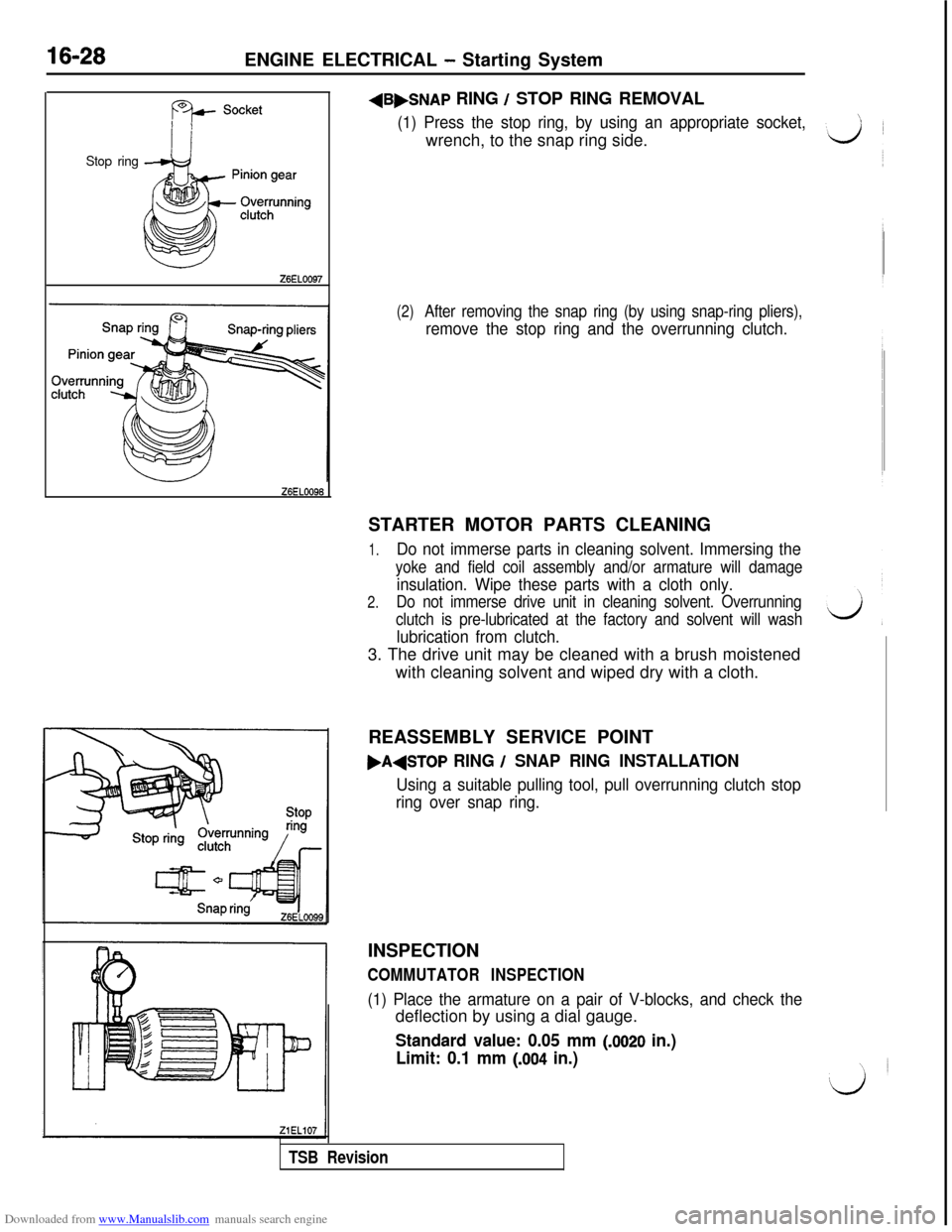
RING / STOP RING REMOVAL
(1) Press the stop ring, by using an appropriate socket,wrench, to the snap ring side.
(2)After removing the snap ring (by using snap-ring pliers),
remove the stop ring and the overrunning clutch.STARTER MOTOR PARTS CLEANING
1.Do not immerse parts in cleaning solvent. Immersing the
yoke and field coil assembly and/or armature will damage
insulation. Wipe these parts with a cloth only.
2.Do not immerse drive unit in cleaning solvent. Overrunning
clutch is pre-lubricated at the factory and solvent will wash
lubrication from clutch.3. The drive unit may be cleaned with a brush moistened
with cleaning solvent and wiped dry with a cloth.
REASSEMBLY SERVICE POINT
,A+TOP RING / SNAP RING INSTALLATION
Using a suitable pulling tool, pull overrunning clutch stop
ring over snap ring.INSPECTION
COMMUTATOR INSPECTION
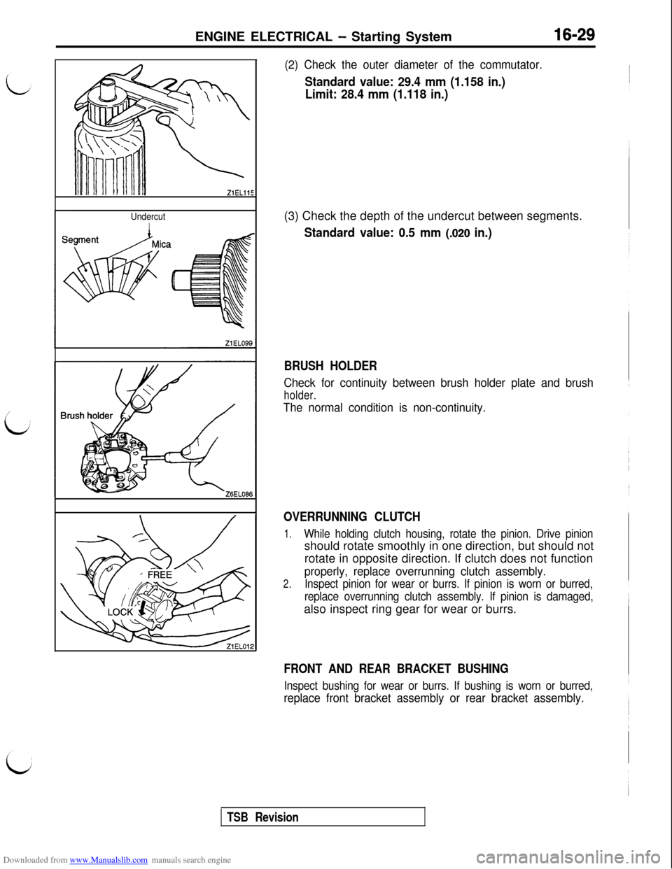
(1) Place the armature on a pair of V-blocks, and check thedeflection by using a dial gauge.
Standard value: 0.05 mm (JO20 in.)
Limit: 0.1 mm
(.004 in.)
TSB Revision
Page 475 of 738
Downloaded from www.Manualslib.com manuals search engine ENGINE ELECTRICAL - Starting System16-29
ZiELllS
UndercutI
(2) Check the outer diameter of the commutator.
Standard value: 29.4 mm (1.158 in.)
Limit: 28.4 mm (1.118 in.)(3) Check the depth of the undercut between segments.
Standard value: 0.5 mm (.020 in.)
BRUSH HOLDER
Check for continuity between brush holder plate and brush
holder.
The normal condition is non-continuity.
OVERRUNNING CLUTCH
1.While holding clutch housing, rotate the pinion. Drive pinionshould rotate smoothly in one direction, but should not
rotate in opposite direction. If clutch does not function
properly, replace overrunning clutch assembly.
2.Inspect pinion for wear or burrs. If pinion is worn or burred,
replace overrunning clutch assembly. If pinion is damaged,also inspect ring gear for wear or burrs.
FRONT AND REAR BRACKET BUSHING
Inspect bushing for wear or burrs. If bushing is worn or burred,
replace front bracket assembly or rear bracket assembly.
TSB Revision
Page 502 of 738
Downloaded from www.Manualslib.com manuals search engine 54-6CHASSIS ELECTRICAL - Ignition Switch
IGNITION SWITCHSPECIAL
TOOL
ToolTool number and nameSupersessionApplication
MB990803
Steering wheel pullerGeneral service toolRemoval of steering wheel
IGNITION SWITCHREMOVAL AND INSTALLATION
40 Nm29 ft.lbs.6 Nm
6
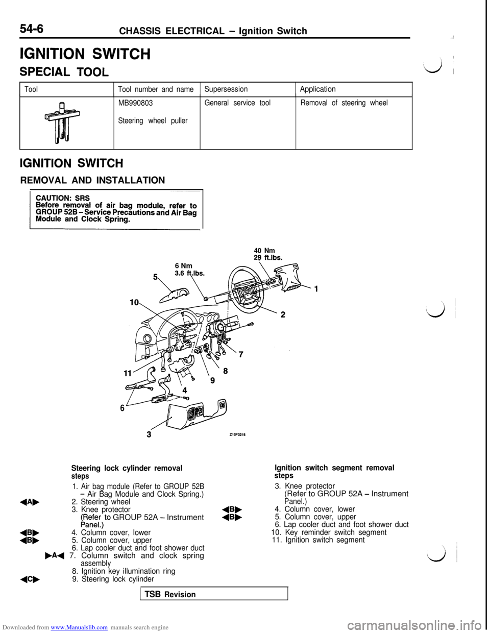
Steering lock cylinder removalsteps
Ignition switch segment removalsteps
1. Air bag module (Refer to GROUP 52B
4Ab
- Air Bag Module and Clock Spring.)3. Knee protector
2. Steering wheel(Refer to GROUP 52A - Instrument
3. Knee protector
Panel.)
LRedE;)to GROUP 52A - Instrument:i:4. Column cover, lower
5. Column cover, upper
:::4. Column cover, lower6. Lap cooler duct and foot shower duct
5. Column cover, upper10. Key reminder switch segment
6. Lap cooler duct and foot shower duct11. Ignition switch segment
,A+ 7. Column switch and clock springassembly
NW
8. Ignition key illumination ring
9. Steering lock cylinder
TSB Revision
Page 503 of 738
Downloaded from www.Manualslib.com manuals search engine CHASSIS ELECTRICAL - Ignition Switch54-7REMOVAL SERVICE POINTS
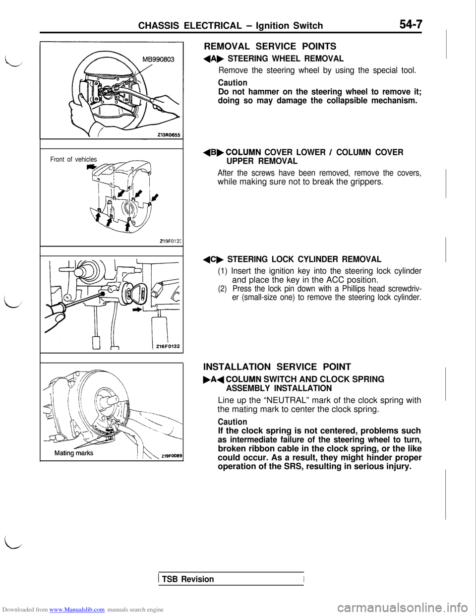
+A, STEERING WHEEL REMOVAL
Remove the steering wheel by using the special tool.
Caution
Do not hammer on the steering wheel to remove it;
doing so may damage the collapsible mechanism.
Front of vehicles
219FO12:
+B,COLUMN COVER LOWER / COLUMN COVER
UPPER REMOVAL
After the screws have been removed, remove the covers,while making sure not to break the grippers.
+C, STEERING LOCK CYLINDER REMOVAL
(1) Insert the ignition key into the steering lock cylinderand place the key in the ACC position.
(2)Press the lock pin down with a Phillips head screwdriv-
er (small-size one) to remove the steering lock cylinder.INSTALLATION SERVICE POINT
.A+COLUMN SWITCH AND CLOCK SPRING
ASSEMBLY INSTALLATIONLine up the “NEUTRAL” mark of the clock spring with
the mating mark to center the clock spring.
CautionIf the clock spring is not centered, problems such
as intermediate failure of the steering wheel to turn,broken ribbon cable in the clock spring, or the like
could occur. As a result, they might hinder proper
operation of the SRS, resulting in serious injury.
iI
1 TSB RevisionI
Page 514 of 738
Downloaded from www.Manualslib.com manuals search engine 54-18CHASSIS ELECTRICAL - Meters and Gauges
OPERATION
When the ignition key is at the “ON” position,the fuel gauge is activated.
l
When there is much fuel, the unit’s resistanceis small and the current flowing in the circuit
is great, so the gauge’s indicator indicates inthe “F” area.
l When there is little fuel, the unit’s resistance
is high and the current flowing in the circuit
is small, so the gauge’s indicator indicates inthe
“E” area.
lWhen the ignition key is at the “ON” position,
the engine coolant temperature gauge is acti-
vated.l
When the engine coolant temperature is high,
the unit’s resistance is low and there is a greatflow of current in the circuit, so the gauge’s
indicator indicates in the “H” area.
l
When the engine coolant temperature is low,
the unit’s resistance is high and there is a smallflow of current in the circuit, so the gauge’s
indicator indicates in the “C” area.
vehicle speed, and vehicle-speed signals areinput to systems (the MFI system, etc.) that
regulate according to the vehicle speed.
TROUBLESHOOTING HINTS
1.The fuel gauge doesn’t function, or shows the
incorrect indication.
(1) Disconnect the connector of the fuel pumpand gauge unit assembly; the ‘F” side is
indicated when terminal (5) is then
grounded.l Check the fuel gauge.
2.The engine coolant temperature gauge doesn’t
function, or shows the incorrect indication.
(1)The “l-l” side is indicated when the connector
of the engine coolant temperature gauge
unit is disconnected and then grounded.l
Check the engine coolant temperature
gauge unit.
3. Systems dependent upon control according to
the vehicle speed do not function correctly.l Check the reed switch (mechanical
speedometer type)l Check the speed sensor (electrical
speedometer type)
coil pressure gauge>l
When the ignition key is at the “ON” position,
the oil pressure gauge is activated.
lWhen oil pressure is high, the internal contacts
of the gauge unit are kept closed for a longerperiod of time. This causes more current to
flow in the circuit, and the gauge pointer swings
to the high pressure side.
lWhen oil pressure is low, the internal contactsof the gauge unit open in a shorter period of
time. Therefore, there is less current flowing
in the circuit and the gauge pointer swings to
the low pressure side.
lWhen the ignition key is set to the “ON” position,the gauge indicator will be at
“0”.l
When the engine is started, the indicator will
move from
“0” to the minus (-) side, and then,as the boost level increases, it will move to
the plus
(+) side.
position, the voltage gauge operates and indi-
cates a battery voltage of approximately 12 V.l
When the engine is started, the voltage gauge
indicates a battery voltage of 12 to 16 V, indicat-ing that the battery is on charge.
4. The oil pressure gauge doesn’t function, or
shows the incorrect indication.
(1)The “H” side is indicated when the connectorof the oil pressure gauge unit is discon-
nected and then grounded.l Check the oil pressure gauge unit.
5.The meter illumination light does not illuminate.
(1) The tail lights illuminate.l Check the rheostat.
6. The voltage gauge doesn’t function, or shows
the incorrect indication.l Check the voltage gauge.
TSB Revision
Page 528 of 738
Downloaded from www.Manualslib.com manuals search engine 54-32CHASSIS ELECTRICAL - Meters and Gauges
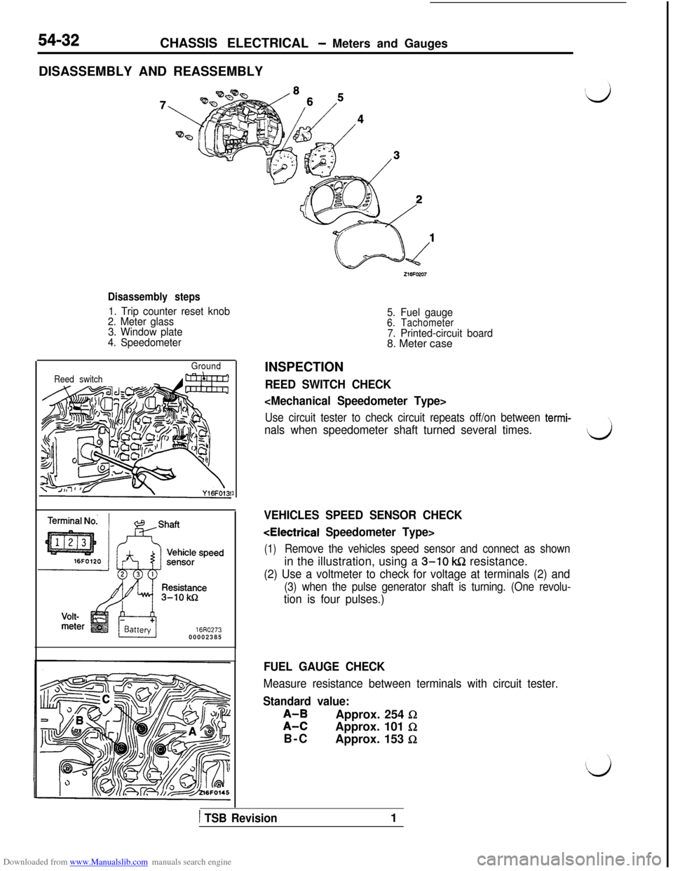
DISASSEMBLY AND REASSEMBLY
Disassembly steps
1. Trip counter reset knob
2. Meter glass
3. Window plate
4. Speedometer
Ground
Reed switch
16R027300002385
3
5. Fuel gauge6. Tachometer7. Printed-circuit board8. Meter case
INSPECTION
REED SWITCH CHECK
Use circuit tester to check circuit repeats off/on between termi-\
nals when speedometer shaft turned several times.d
VEHICLES SPEED SENSOR CHECK
(1)Remove the vehicles speed sensor and connect as shownin the illustration, using a
3-10 k&2 resistance.
(2) Use a voltmeter to check for voltage at terminals (2) and
(3) when the pulse generator shaft is turning. (One revolu-
tion is four pulses.)
FUEL GAUGE CHECK
Measure resistance between terminals with circuit tester.
Standard value:
;I;Approx. 254 0Approx. 101
I2B-C
Approx. 153
fi
1 TSB Revision1
Page 529 of 738
Downloaded from www.Manualslib.com manuals search engine CHASSIS ELECTRICAL - Meters and Gauges
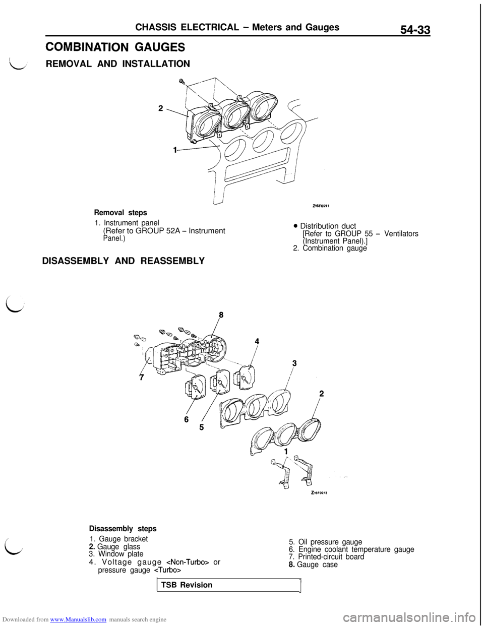
COMBINATION GAUGESREMOVAL AND INSTALLATION
54-33
Removal steps
1. Instrument panel(Refer to GROUP 52A
- InstrumentPanel.)
0 Distribution duct[Refer to GROUP 55 - Ventilators
(Instrument Panel).]
2. Combination gaugeDISASSEMBLY AND REASSEMBLY
i;
Disassembly steps
1. Gauge bracket2. Gauge glass
3. Window plate4. Voltage gauge
pressure gauge
5. Oil pressure gauge
6. Engine coolant temperature gauge
7. Printed-circuit board
8. Gauge caseTSB Revision
J