code 43 MITSUBISHI 3000GT 1996 2.G Workshop Manual
[x] Cancel search | Manufacturer: MITSUBISHI, Model Year: 1996, Model line: 3000GT, Model: MITSUBISHI 3000GT 1996 2.GPages: 738, PDF Size: 35.06 MB
Page 68 of 738
Downloaded from www.Manualslib.com manuals search engine CIRCUIT DIAGRAMS - How to Read Circuit Diagrams
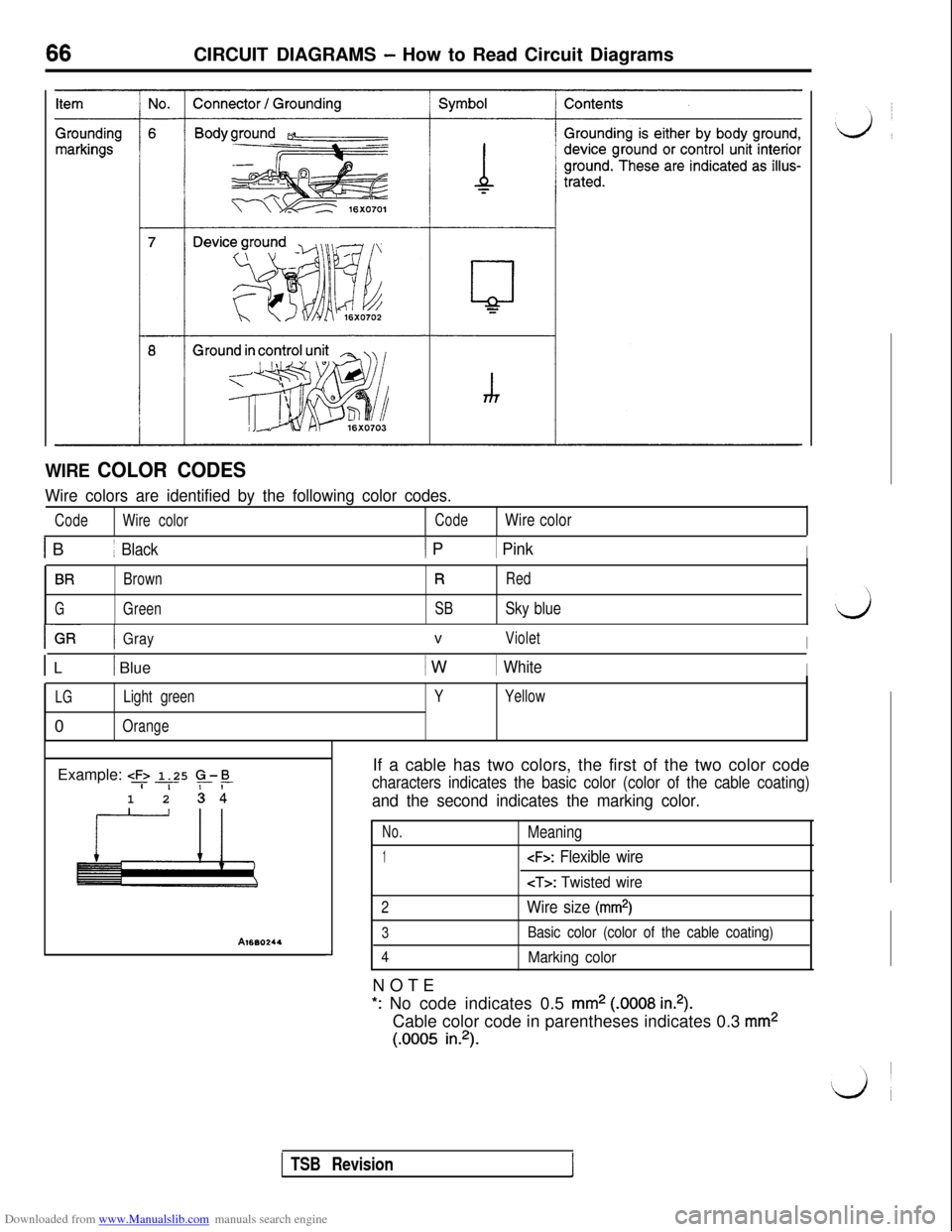
WIRE COLOR CODES
Wire colors are identified by the following color codes.
CodeWire colorCodeWire color
1 B1 Black1 P1 PinkI
BRBrownRRed
GGreenSBSky blue
I~-- IGRGrayvVioletI
1 L1 Blue1 W1 WhiteI
LGLight green0
OrangeYYellowExample:
e+ 1.25 5-E-i-1 2 cl
Al660244-1If a cable has two colors, the first of the two color code
characters indicates the basic color (color of the cable coating)
and the second indicates the marking color.
No.
1
2
3
4NOTE
Meaning
Basic color (color of the cable coating)
Marking color
*: No code indicates 0.5 mm2 (.0008 in.2).Cable color code in parentheses indicates 0.3
mm2
(.0005 in.2).
TSB RevisionI
Page 239 of 738
Downloaded from www.Manualslib.com manuals search engine CIRCUIT DIAGRAMS - Central Door Locking Circuit237
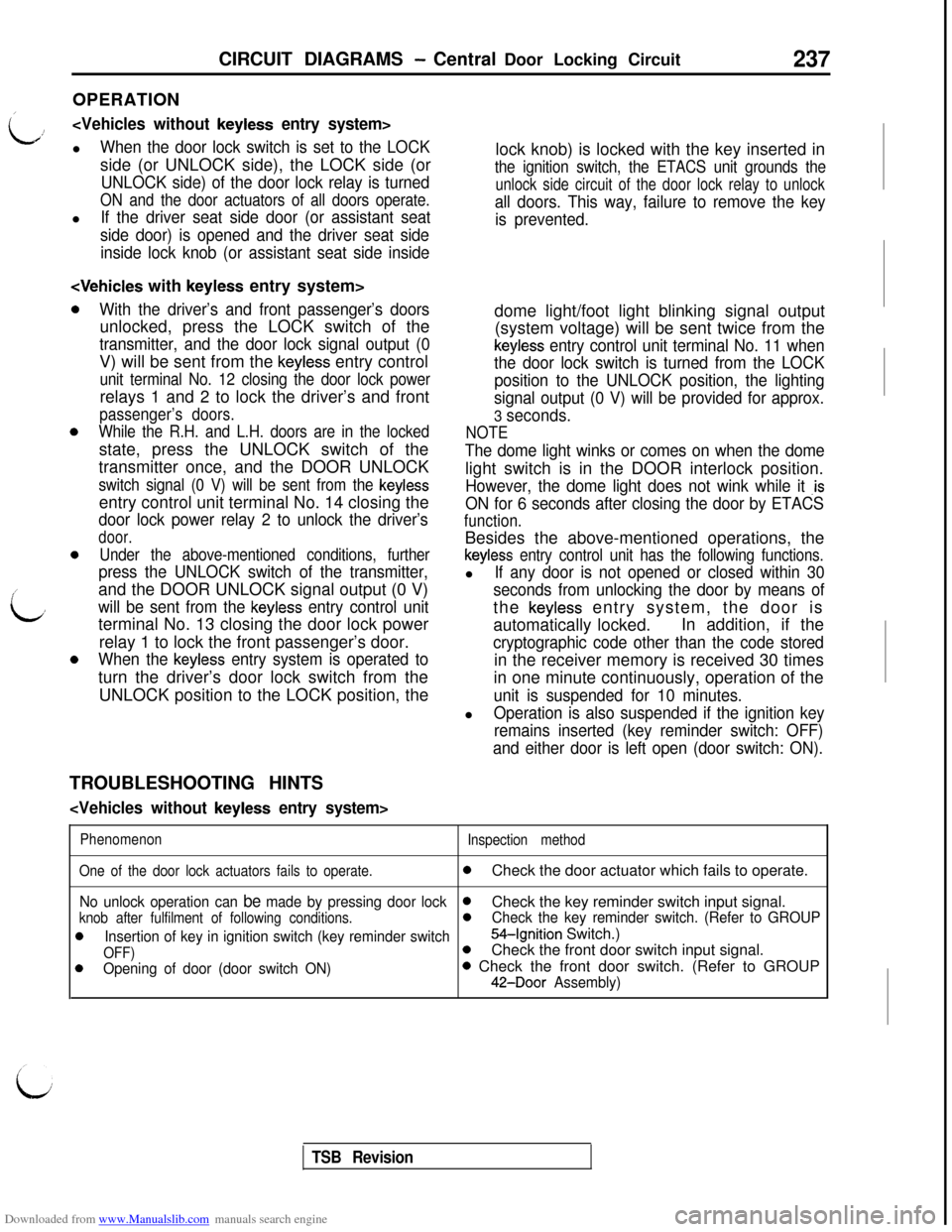
OPERATION/
Li!
When the door lock switch is set to the LOCKside (or UNLOCK side), the LOCK side (or
UNLOCK side) of the door lock relay is turned
ON and the door actuators of all doors operate.l
If the driver seat side door (or assistant seat
side door) is opened and the driver seat side
inside lock knob (or assistant seat side inside
0
,’
id
0
With the driver’s and front passenger’s doorsunlocked, press the LOCK switch of the
transmitter, and the door lock signal output (0V) will be sent from the
keyless entry control
unit terminal No. 12 closing the door lock powerrelays 1 and 2 to lock the driver’s and front
passenger’s doors.
While the R.H. and L.H. doors are in the lockedstate, press the UNLOCK switch of the
transmitter once, and the DOOR UNLOCK
switch signal (0 V) will be sent from the keylessentry control unit terminal No. 14 closing the
door lock power relay 2 to unlock the driver’s
door.
Under the above-mentioned conditions, further
press the UNLOCK switch of the transmitter,and the DOOR UNLOCK signal output (0 V)
will be sent from the keyless entry control unitterminal No. 13 closing the door lock power
relay 1 to lock the front passenger’s door.
When the keyless entry system is operated toturn the driver’s door lock switch from the
UNLOCK position to the LOCK position, thelock knob) is locked with the key inserted in
the ignition switch, the ETACS unit grounds the
unlock side circuit of the door lock relay to unlock
all doors. This way, failure to remove the key
is prevented.dome light/foot light blinking signal output
(system voltage) will be sent twice from the
keyless entry control unit terminal No. 11 when
the door lock switch is turned from the LOCK
position to the UNLOCK position, the lighting
signal output (0 V) will be provided for approx.
3 seconds.
NOTE
The dome light winks or comes on when the domelight switch is in the DOOR interlock position.
However, the dome light does not wink while it .is
ON for 6 seconds after closing the door by ETACS
function.Besides the above-mentioned operations, the
keyless entry control unit has the following functions.l
If any door is not opened or closed within 30
seconds from unlocking the door by means ofthe
keyless entry system, the door is
automatically locked.In addition, if the
cryptographic code other than the code storedin the receiver memory is received 30 times
in one minute continuously, operation of the
unit is suspended for 10 minutes.l
Operation is also suspended if the ignition key
remains inserted (key reminder switch: OFF)
and either door is left open (door switch: ON).TROUBLESHOOTING HINTS
Phenomenon
Inspection method
One of the door lock actuators fails to operate.
0Check the door actuator which fails to operate.
No unlock operation can be made by pressing door lock0
knob after fulfilment of following conditions.Check the key reminder switch input signal.0Check the key reminder switch. (Refer to GROUP
0Insertion of key in ignition switch (key reminder switch54-Ignition Switch.)
OFF)0
0Opening of door (door switch ON)Check the front door switch input signal.0 Check the front door switch. (Refer to GROUP
42-Door Assembly)
TSB Revision
Page 240 of 738
Downloaded from www.Manualslib.com manuals search engine 238CIRCUIT .DIAGRAMS - Central Door Locking Circuit
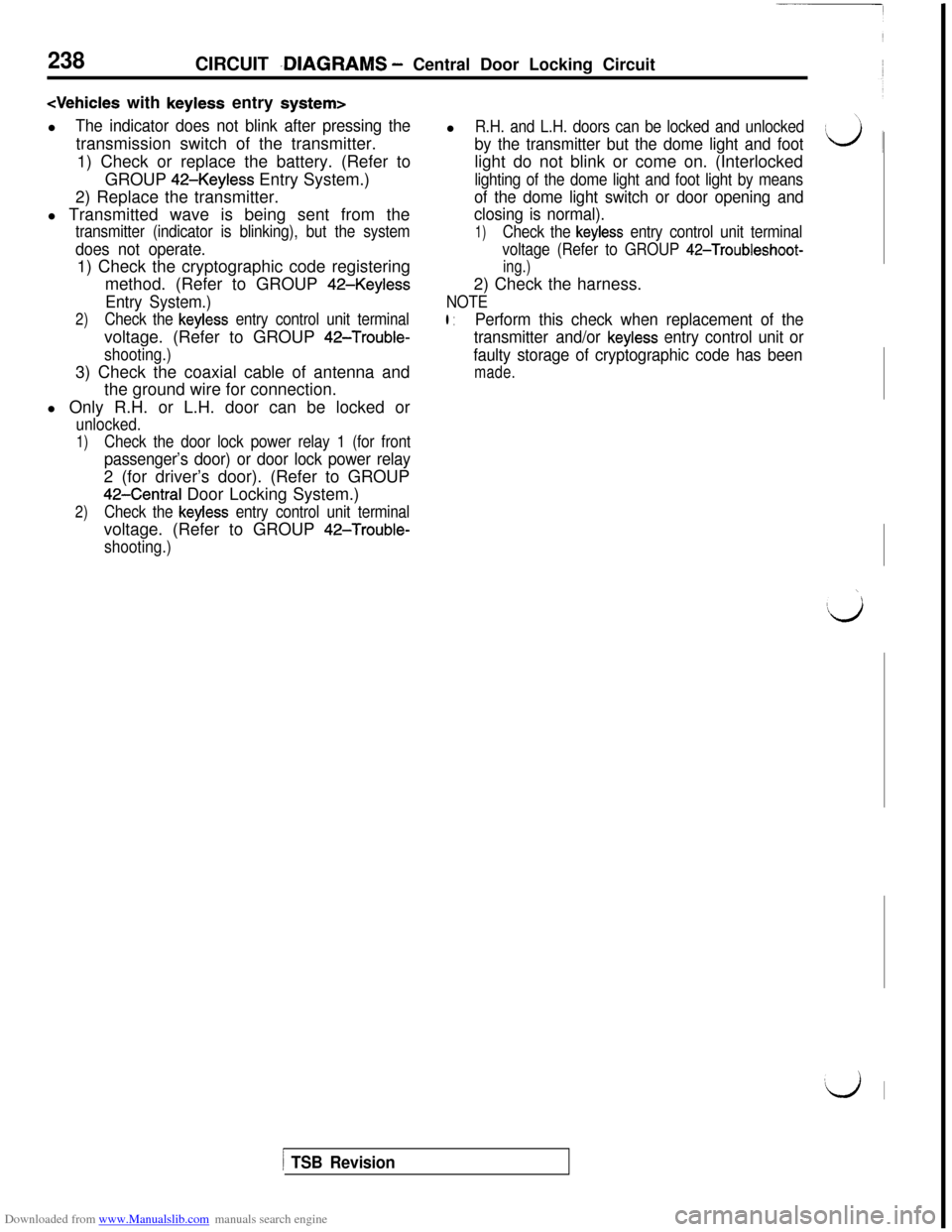
The indicator does not blink after pressing thetransmission switch of the transmitter.
1) Check or replace the battery. (Refer to
GROUP
42-Keyless Entry System.)
2) Replace the transmitter.
l Transmitted wave is being sent from thel
R.H. and L.H. doors can be locked and unlocked
by the transmitter but the dome light and footlight do not blink or come on. (Interlocked
lighting of the dome light and foot light by means
of the dome light switch or door opening and
closing is normal).
transmitter (indicator is blinking), but the system
does not operate.1) Check the cryptographic code registering
method. (Refer to GROUP
42-Keyless
Entry System.)
2)Check the keyless entry control unit terminalvoltage. (Refer to GROUP
42-Trouble-
shooting.)3) Check the coaxial cable of antenna and
the ground wire for connection.
l Only R.H. or L.H. door can be locked or
unlocked.
1)Check the door lock power relay 1 (for front
passenger’s door) or door lock power relay2 (for driver’s door). (Refer to GROUP
42-Central Door Locking System.)
2)Check the keyless entry control unit terminalvoltage. (Refer to GROUP
42-Trouble-
shooting.)
1)Check the keyless entry control unit terminal
voltage (Refer to GROUP
42-Troubleshoot-
ing.)2) Check the harness.
NOTE
l :Perform this check when replacement of the
transmitter and/or
keyless entry control unit or
faulty storage of cryptographic code has been
made.
\
Ilj
‘d I
1 TSB Revision
Page 532 of 738
Downloaded from www.Manualslib.com manuals search engine 54-36CHASSIS ELECTRICAL - Lighting System
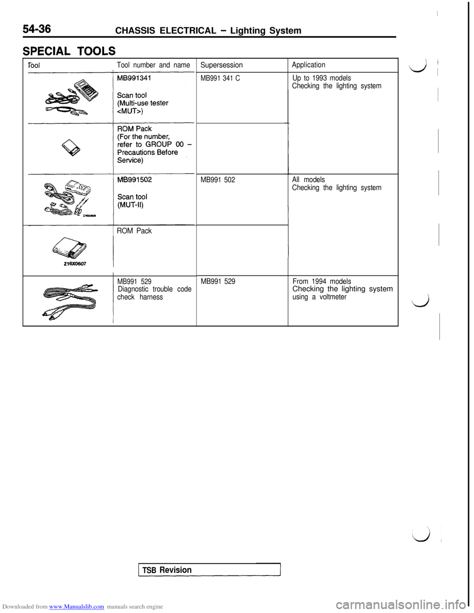
SPECIAL TOOLS
ToolTool number and name
1 ROM Pack
MB991 529Diagnostic trouble code
check harness
Supersession
MB991 341 C
Application
Up to 1993 models
Checking the lighting system
MB991 502All models
Checking the lighting system
MB991 529From 1994 modelsChecking the lighting system
using a voltmeter
I
‘, I
L/i
1
d
TSB Revision
Page 652 of 738
Downloaded from www.Manualslib.com manuals search engine 54-156
CHASSIS ELECTRICAL - Radio and Tape Player
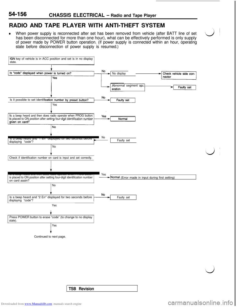
RADIO AND TAPE PLAYER WITH ANTI-THEFT SYSTEM
lWhen power supply is reconnected after set has been removed from vehicle (after BATT line of sethas been disconnected for more than one hour), what can be effectively performed is only supply
of power made by POWER button operation. (If power supply is connected within an hour, operating
state before disconnection of power supply is resumed.)
IGN key of vehicle is in ACC position and set is in no displaystate.
No displayAbnormal segment op-
*[Faulty
tIs it possible to set identifiNom-Faulty
Yes
Is a beep heard and then does radio operate when PROG button
is placed to ON position after setting four-digit identification numberIs a beep heard and “1 Err” displayed for two seconds before
No
displaying “code”?cFaulty set
No
tCheck if identification number on card is input and set correctly.
Is a beep heard and then does radio operate when PROG button
is placed to ON position after setting four-digit identification numberon card aaain?
Yes-----+ NomxJ (Error made in input during first setting)
I
NoIs a beep heard and “2 Err” displayed for two seconds before
displaying “code”?Faulty set
YesPress POWER button to erase “code” (to change to no display
state).
I
YesContinued to next page.
TSB Revision
Page 653 of 738
Downloaded from www.Manualslib.com manuals search engine CHASSIS ELECTRICAL - Radio-and Tape Player54-I 57
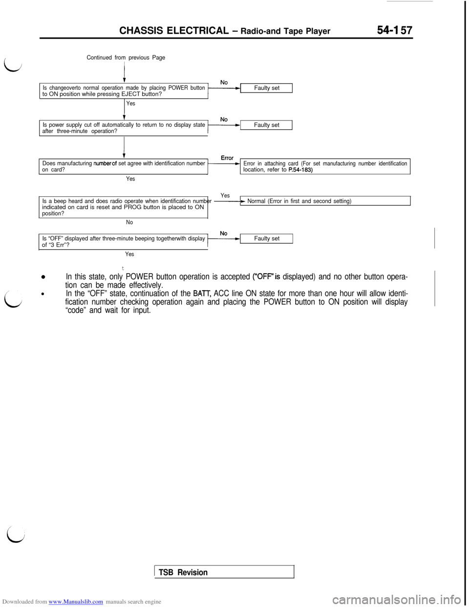
Continued from previous Page
I
Is changeoverto normal operation made by placing POWER buttonto ON position while pressing EJECT button?
YesFaulty set
tIs power supply cut off automatically to return to no display state
after three-minute operation?Faulty set
Does manufacturing numberof set agree with identification number
on card?
YesError in attaching card (For set manufacturing number identificationlocation, refer to
F!54-183)
Yes
Is a beep heard and does radio operate when identification number - Normal (Error in first and second setting)indicated on card is reset and PROG button is placed to ON
position?
No
Is “OFF” displayed after three-minute beeping togetherwith displayof “3 Err”?Faulty set
Yes
t
0In this state, only POWER button operation is accepted (“OFF’is displayed) and no other button opera-
tion can be made effectively.l
In the “OFF” state, continuation of the BAlT, ACC line ON state for more than one hour will allow identi-
fication number checking operation again and placing the POWER button to ON position will display
“code” and wait for input.
1 TSB Revision
Page 679 of 738
Downloaded from www.Manualslib.com manuals search engine CHASSIS ELECTRICAL - Radio- and TaDe Plaver54-183
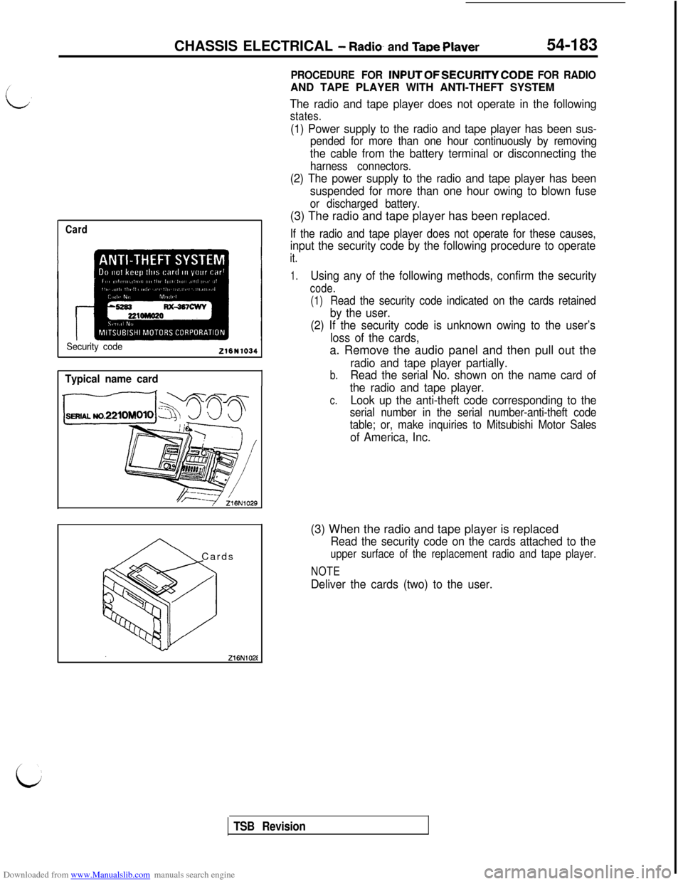
Card
Security code216N1034
Typical name card
A Cards
PROCEDURE FOR INPUTOFSECURITYCODE FOR RADIOAND TAPE PLAYER WITH ANTI-THEFT SYSTEM
The radio and tape player does not operate in the following
states.
(1) Power supply to the radio and tape player has been sus-
pended for more than one hour continuously by removing
the cable from the battery terminal or disconnecting the
harness connectors.
(2) The power supply to the radio and tape player has been
suspended for more than one hour owing to blown fuse
or discharged battery.(3) The radio and tape player has been replaced.
If the radio and tape player does not operate for these causes,
input the security code by the following procedure to operate
it.
1.Using any of the following methods, confirm the security
code.
(1)
Read the security code indicated on the cards retained
by the user.
(2) If the security code is unknown owing to the user’s
loss of the cards,a. Remove the audio panel and then pull out the
radio and tape player partially.
b.Read the serial No. shown on the name card of
the radio and tape player.
c.Look up the anti-theft code corresponding to the
serial number in the serial number-anti-theft code
table; or, make inquiries to Mitsubishi Motor Sales
of America, Inc.(3) When the radio and tape player is replaced
Read the security code on the cards attached to the
upper surface of the replacement radio and tape player.
NOTE
Deliver the cards (two) to the user.
TSB Revision
Page 680 of 738
Downloaded from www.Manualslib.com manuals search engine 54-184CHASSIS ELECTRICAL - Radio and Tape Plaver
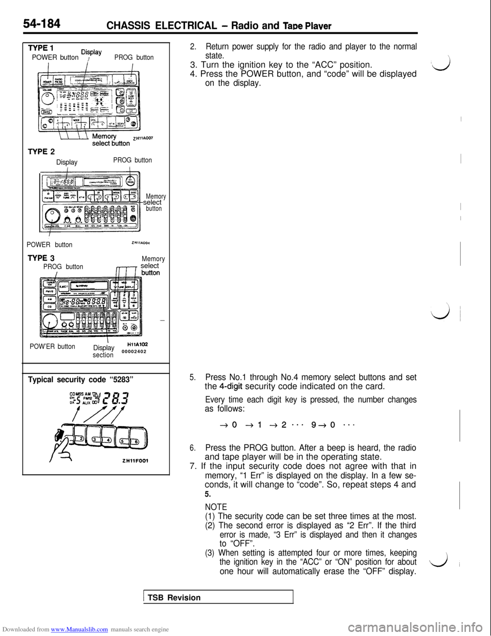
TYPE 1
POWER button Disp’ayPROG button
TYPE 2
DisplayPROG button
Memoryselect
button
POWER button
TYPE 3
PROG button
ZHllA004
Memory,1r select
POW’ER buttonIDisplayH’llAlM
section00002402
Typical security code “5283”
ZHllFOOl
2.Return power supply for the radio and player to the normal
state.3. Turn the ignition key to the “ACC” position.
4. Press the POWER button, and “code” will be displayed
on the display.
5.Press No.1 through No.4 memory select buttons and setthe
4-digit security code indicated on the card.
Every time each digit key is pressed, the number changes
as follows:
40 +l +2--e 9+0 **-
6.Press the PROG button. After a beep is heard, the radioand tape player will be in the operating state.
7. If the input security code does not agree with that in
memory, “1 Err” is displayed on the display. In a few se-conds, it will change to “code”. So, repeat steps 4 and
5.
NOTE
(1) The security code can be set three times at the most.
(2) The second error is displayed as “2 Err”. If the third
error is made, “3 Err” is displayed and then it changes
to “OFF”.
(3) When setting is attempted four or more times, keeping
the ignition key in the “ACC” or “ON” position for about
one hour will automatically erase the “OFF” display.
\
,ij~
I
I
I
\,
LJ
1 TSB Revision
Page 701 of 738
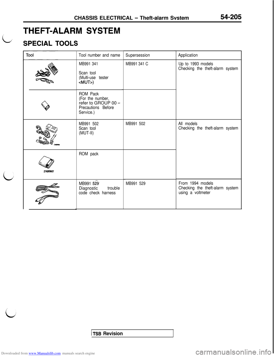
Downloaded from www.Manualslib.com manuals search engine CHASSIS ELECTRICAL - Theft-alarm Svstem54-205
THEFT-ALARM SYSTEM
L,
SPECIAL TOOLS
L
Q
Tool number and name
MB991 341
Scan tool
(Multi-use tester
ROM Pack
(For the number,refer to GROUP 00
-
Precautions Before
Service.)
MB991 502
Scan tool
(MUT-II)
ROM pack
MB991
52%.
Diagnostictrouble
code check harnessSupersession
MB991 341 C
MB991 502
MB991 529
i
1 TSB Revision
Application
Up to 1993 models
Checking the theft-alarm system
All models
Checking the theft-alarm system
From 1994 models
Checking the theft-alarm system
using a voltmeter