key MITSUBISHI 380 2005 Workshop Manual
[x] Cancel search | Manufacturer: MITSUBISHI, Model Year: 2005, Model line: 380, Model: MITSUBISHI 380 2005Pages: 1500, PDF Size: 47.87 MB
Page 1246 of 1500
PRECAUTIONS BEFORE SERVICE
GENERAL00-25
APPLICATION OF ANTI-CORROSION AGENTS
AND UNDERCOATS
M1001011000043
Do not to apply oil or grease to the heated oxygen sensor. If
applied, the sensor may malfunction. Protect the heated oxy-
gen sensor with a cover before applying anti-corrosion agent,
etc.
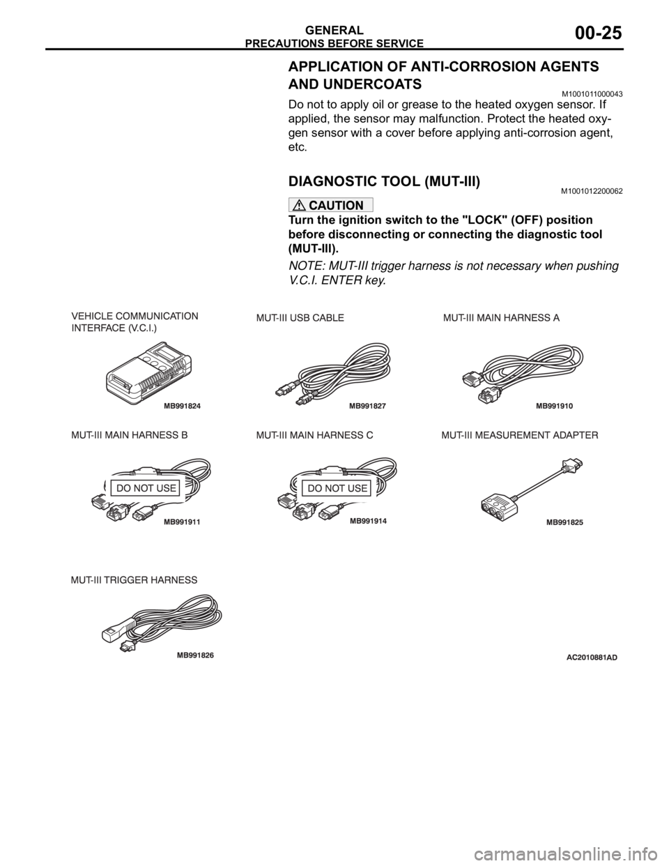
DIAGNOSTIC TOOL (MUT-III)M1001012200062
Turn the ignition switch to the "LOCK" (OFF) position
before disconnecting or connecting the diagnostic tool
(MUT-III).
NOTE: MUT-III trigger harness is not necessary when pushing
V.C.I. ENTER key.
Page 1247 of 1500
TOWING AND HOISTING
GENERAL00-26
TOWING AND HOISTINGM1001000800380
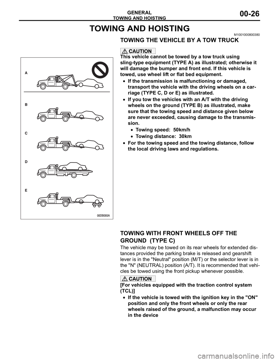
TOWING THE VEHICLE BY A TOW TRUCK
.
This vehicle cannot be towed by a tow truck using
sling-type equipment (TYPE A) as illustrated; otherwise it
will damage the bumper and front end. If this vehicle is
towed, use wheel lift or flat bed equipment.
If the transmission is malfunctioning or damaged,
transport the vehicle with the driving wheels on a car-
riage (TYPE C, D or E) as illustrated.
If you tow the vehicles with an A/T with the driving
wheels on the ground (TYPE B) as illustrated, make
sure that the towing speed and distance given below
are never exceeded, causing damage to the transmis-
sion.
Towing speed: 50km/h
Towing distance: 30km
For the towing speed and the towing distance, follow
the local driving laws and regulations.
.
TOWING WITH FRONT WHEELS OFF THE
GROUND (TYPE C)
The vehicle may be towed on its rear wheels for extended dis-
tances provided the parking brake is released and gearshift
lever is in the "Neutral" position (M/T) or the selector lever is in
the "N" (NEUTRAL) position (A/T). It is recommended that vehi-
cles be towed using the front pickup whenever possible.
[For vehicles equipped with the traction control system
(TCL)]
If the vehicle is towed with the ignition key in the "ON"
position and only the front wheels or only the rear
wheels raised of the ground, a malfunction may occur
in the device
.
Page 1248 of 1500
TOWING AND HOISTING
GENERAL00-27
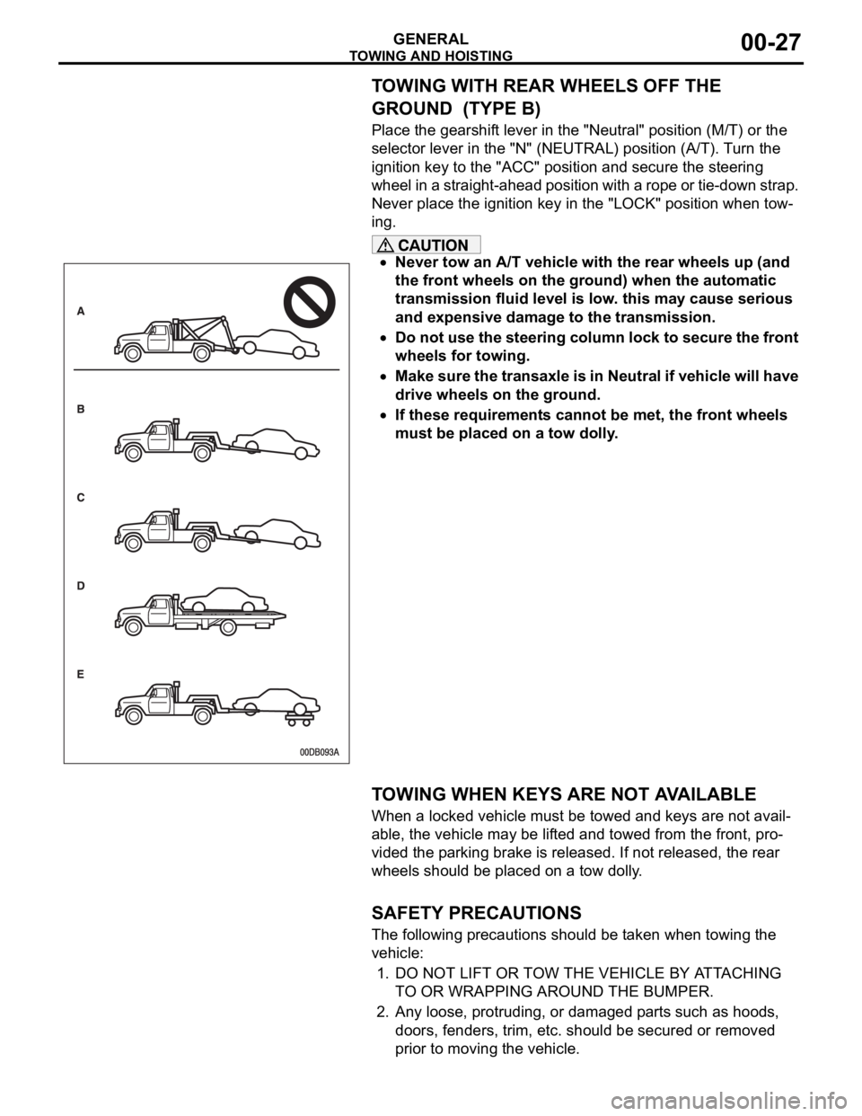
TOWING WITH REAR WHEELS OFF THE
GROUND (TYPE B)
Place the gearshift lever in the "Neutral" position (M/T) or the
selector lever in the "N" (NEUTRAL) position (A/T). Turn the
ignition key to the "ACC" position and secure the steering
wheel in a straight-ahead position with a rope or tie-down strap.
Never place the ignition key in the "LOCK" position when tow-
ing.
Never tow an A/T vehicle with the rear wheels up (and
the front wheels on the ground) when the automatic
transmission fluid level is low. this may cause serious
and expensive damage to the transmission.
Do not use the steering column lock to secure the front
wheels for towing.
Make sure the transaxle is in Neutral if vehicle will have
drive wheels on the ground.
If these requirements cannot be met, the front wheels
must be placed on a tow dolly.
.
TOWING WHEN KEYS ARE NOT AVAILABLE
When a locked vehicle must be towed and keys are not avail-
able, the vehicle may be lifted and towed from the front, pro-
vided the parking brake is released. If not released, the rear
wheels should be placed on a tow dolly.
.
SAFETY PRECAUTIONS
The following precautions should be taken when towing the
vehicle:
1. DO NOT LIFT OR TOW THE VEHICLE BY ATTACHING
TO OR WRAPPING AROUND THE BUMPER.
2. Any loose, protruding, or damaged parts such as hoods,
doors, fenders, trim, etc. should be secured or removed
prior to moving the vehicle.
Page 1272 of 1500
MAINTENANCE SERVICE
GENERAL00-51
18. SUSPENSION SYSTEM (INSPECT FOR
LOOSENESS AND DAMAGE)
M1001009600048
Visually inspect the front/rear suspension components for dete-
rioration and damage. Re-tighten the front/rear suspension
components retaining bolts to specified torque.
19. SRS AIR BAG (INSPECT FOR SRS SYSTEM)M1001003700326
The entire SRS including air bag and pre-tensioner seat belt
must be inspected by an authorized MITSUBISHI MOTORS
dealer 10 years.
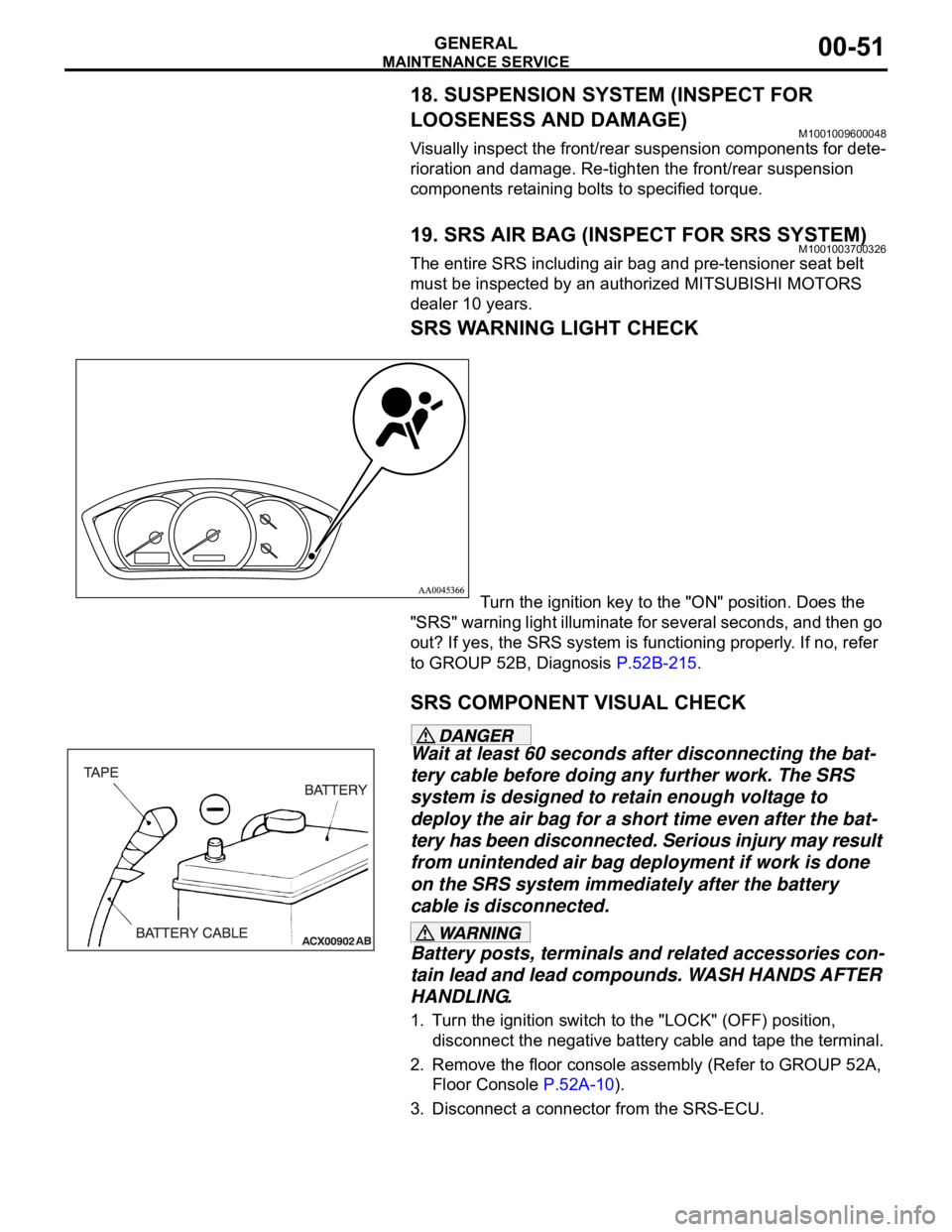
SRS WARNING LIGHT CHECK
Turn the ignition key to the "ON" position. Does the
"SRS" warning light illuminate for several seconds, and then go
out? If yes, the SRS system is functioning properly. If no, refer
to GROUP 52B, Diagnosis P.52B-215.
SRS COMPONENT VISUAL CHECK
Wait at least 60 seconds after disconnecting the bat-
tery cable before doing any further work. The SRS
system is designed to retain enough voltage to
deploy the air bag for a short time even after the bat-
tery has been disconnected. Serious injury may result
from unintended air bag deployment if work is done
on the SRS system immediately after the battery
cable is disconnected.
Battery posts, terminals and related accessories con-
tain lead and lead compounds. WASH HANDS AFTER
HANDLING.
1. Turn the ignition switch to the "LOCK" (OFF) position,
disconnect the negative battery cable and tape the terminal.
2. Remove the floor console assembly (Refer to GROUP 52A,
Floor Console P.52A-10).
3. Disconnect a connector from the SRS-ECU.
Page 1324 of 1500
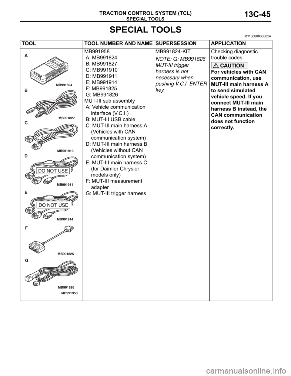
SPECIAL TOOLS
TRACTION CONTROL SYSTEM (TCL)13C-45
SPECIAL TOOLSM1136000600024
TOOL TOOL NUMBER AND NAME SUPERSESSION APPLICATION
MB991958
A: MB991824
B: MB991827
C: MB991910
D: MB991911
E: MB991914
F: MB991825
G: MB991826
MUT-III sub assembly
A: Vehicle communication
interface (V.C.I.)
B: MUT-III USB cable
C: MUT-III main harness A
(Vehicles with CAN
communication system)
D: MUT-III main harness B
(Vehicles without CAN
communication system)
E: MUT-III main harness C
(for Daimler Chrysler
models only)
F: MUT-III measurement
adapter
G: MUT-III trigger harnessMB991824-KIT
NOTE: G: MB991826
MUT-III trigger
harness is not
necessary when
pushing V.C.I. ENTER
key.Checking diagnostic
trouble codes
For vehicles with CAN
communication, use
MUT-III main harness A
to send simulated
vehicle speed. If you
connect MUT-III main
harness B instead, the
CAN communication
does not function
correctly.
Page 1339 of 1500
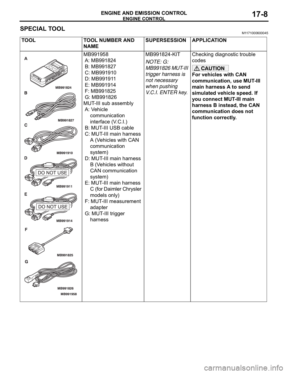
ENGINE CONTROL
ENGINE AND EMISSION CONTROL17-8
SPECIAL TOOLM1171000600045
TOOL TOOL NUMBER AND
NAMESUPERSESSION APPLICATION
MB991958
A: MB991824
B: MB991827
C: MB991910
D: MB991911
E: MB991914
F: MB991825
G: MB991826
MUT-III sub assembly
A: Vehicle
communication
interface (V.C.I.)
B: MUT-III USB cable
C: MUT-III main harness
A (Vehicles with CAN
communication
system)
D: MUT-III main harness
B (Vehicles without
CAN communication
system)
E: MUT-III main harness
C (for Daimler Chrysler
models only)
F: MUT-III measurement
adapter
G: MUT-III trigger
harnessMB991824-KIT
NOTE: G:
MB991826 MUT-III
trigger harness is
not necessary
when pushing
V.C.I. ENTER key.Checking diagnostic trouble
codes
For vehicles with CAN
communication, use MUT-III
main harness A to send
simulated vehicle speed. If
you connect MUT-III main
harness B instead, the CAN
communication does not
function correctly.
Page 1400 of 1500
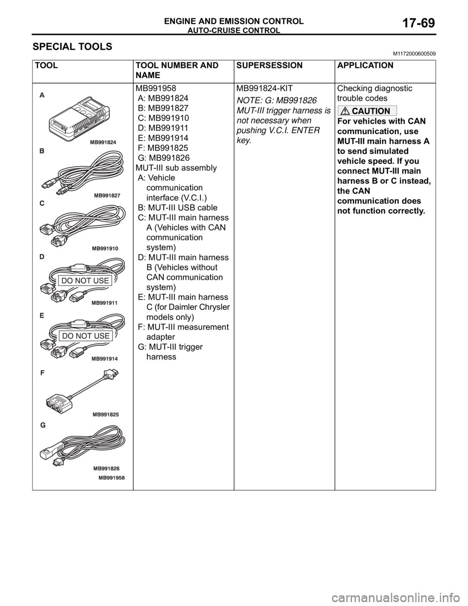
AUTO-CRUISE CONTROL
ENGINE AND EMISSION CONTROL17-69
SPECIAL TOOLSM1172000600509
TOOL TOOL NUMBER AND
NAMESUPERSESSION APPLICATION
MB991958
A: MB991824
B: MB991827
C: MB991910
D: MB991911
E: MB991914
F: MB991825
G: MB991826
MUT-III sub assembly
A: Vehicle
communication
interface (V.C.I.)
B: MUT-III USB cable
C: MUT-III main harness
A (Vehicles with CAN
communication
system)
D: MUT-III main harness
B (Vehicles without
CAN communication
system)
E: MUT-III main harness
C (for Daimler Chrysler
models only)
F: MUT-III measurement
adapter
G: MUT-III trigger
harnessMB991824-KIT
NOTE: G: MB991826
MUT-III trigger harness is
not necessary when
pushing V.C.I. ENTER
key.Checking diagnostic
trouble codes
For vehicles with CAN
communication, use
MUT-III main harness A
to send simulated
vehicle speed. If you
connect MUT-III main
harness B or C instead,
the CAN
communication does
not function correctly.