light MITSUBISHI 380 2005 Workshop Manual
[x] Cancel search | Manufacturer: MITSUBISHI, Model Year: 2005, Model line: 380, Model: MITSUBISHI 380 2005Pages: 1500, PDF Size: 47.87 MB
Page 1303 of 1500
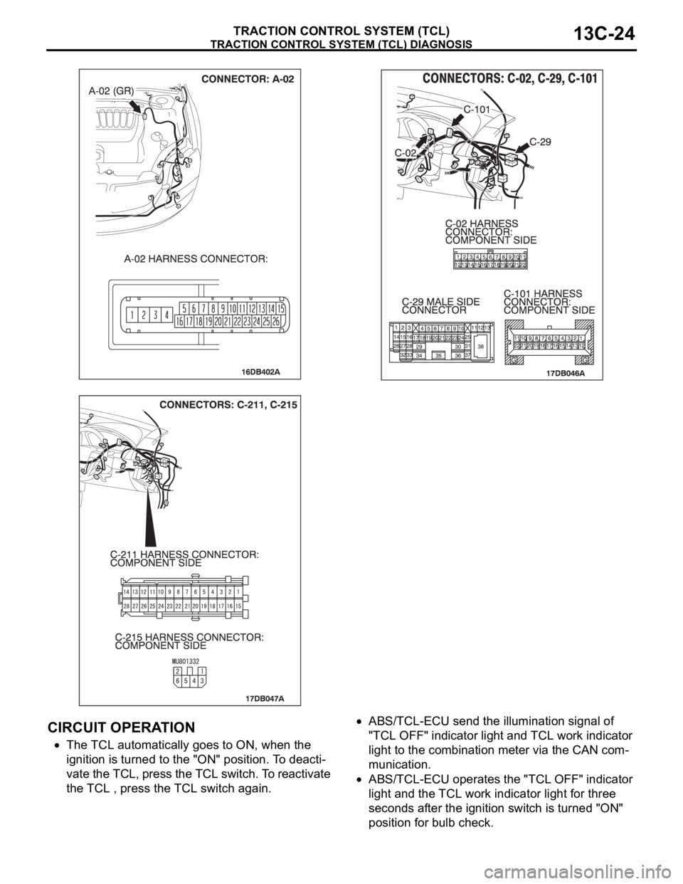
TRACTION CONTROL SYSTEM (TCL) DIAGNOSIS
TRACTION CONTROL SYSTEM (TCL)13C-24
.
CIRCUIT OPERATION
The TCL automatically goes to ON, when the
ignition is turned to the "ON" position. To deacti-
vate the TCL, press the TCL switch. To reactivate
the TCL , press the TCL switch again.
ABS/TCL-ECU send the illumination signal of
"TCL OFF" indicator light and TCL work indicator
light to the combination meter via the CAN com-
munication.
ABS/TCL-ECU operates the "TCL OFF" indicator
light and the TCL work indicator light for three
seconds after the ignition switch is turned "ON"
position for bulb check.
Page 1307 of 1500
TRACTION CONTROL SYSTEM (TCL) DIAGNOSIS
TRACTION CONTROL SYSTEM (TCL)13C-28
STEP 4. Retest the system
Q: Turn the ignition switch to the "ON" position. Do the
"TCL OFF" indicator light and the TCL work indicator
light illuminate for three seconds, and then go out after
the engine starts?
YES : The procedure is complete.
NO : . Return to Step 1.
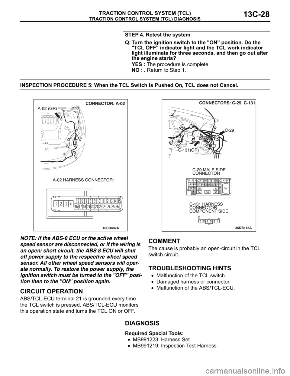
INSPECTION PROCEDURE 5: When the TCL Switch is Pushed On, TCL does not Cancel.
NOTE: If the ABS-8 ECU or the active wheel
speed sensor are disconnected, or if the wiring is
an open/ short circuit, the ABS 8 ECU will shut
off power supply to the respective wheel speed
sensor. All other wheel speed sensors will oper-
ate normally. To restore the power supply, the
ignition switch must be turned to the "OFF" posi-
tion then to the "ON" position again.
.
CIRCUIT OPERATION
ABS/TCL-ECU terminal 21 is grounded every time
the TCL switch is pressed. ABS/TCL-ECU monitors
this operation state and turns the TCL ON or OFF.
.
COMMENT
The cause is probably an open-circuit in the TCL
switch circuit.
.
TROUBLESHOOTING HINTS
Malfunction of the TCL switch.
Damaged harness or connector.
Malfunction of the ABS/TCL-ECU.
DIAGNOSIS
Required Special Tools:
MB991223: Harness Set
MB991219: Inspection Test Harness
Page 1315 of 1500

TRACTION CONTROL SYSTEM (TCL) DIAGNOSIS
TRACTION CONTROL SYSTEM (TCL)13C-36
DATA LIST REFERENCE TABLEM1136003500071
NOTE: If the ABS-8 ECU or the active wheel
speed sensor are disconnected, or if the wiring is
an open/ short circuit, the ABS 8 ECU will shut
off power supply to the respective wheel speed
sensor. All other wheel speed sensors will oper-
ate normally. To restore the power supply, the
ignition switch must be turned to the "OFF" posi-
tion then to the "ON" position again.The following items can be read by the diagnostic
tool from the ABS/TCL-ECU input data. (Refer to
P.13C-3).
NOTE: Since the TCL is controlled with the same ABS/TCL-ECU used to control the ABS, the stoplight switch
check item (No.6) used only for the ABS also appear.MUT-III
DIAGNOSTI
C TOOL
DISPLAYITEM
NO.CHECK ITEM CHECKING REQUIREMENTS NORMAL
VA L U E
FL wheel
speed sensor01 Front left wheel speed sensor Drive the vehicle Vehicle speeds
displayed on the
speedometer
and diagnostic
tool are identical. FR wheel
speed sensor02 Front right wheel speed sensor
RL wheel
speed sensor03 Rear left wheel speed sensor
RR wheel
speed sensor04 Rear right left wheel speed
sensor
Power supply
voltage05 ABS/TCL-ECU power supply
voltageIgnition switch power supply
voltageBattery positive
voltage
Stoplamp
switch
(input)*06 Stoplamp switch Depress the brake pedal. ON
Release the brake pedal. OFF
Stoplamp
switch*13 Stoplamp switch Depress the brake pedal. ON
Release the brake pedal. OFF
Pump motor 21 Pump motor When the ABS outputs the
operation permission signal
during drivingON
When the ABS outputs the
operation permission signal
during drivingOFF
Valve relay 30 Valve relayWhen the ABS outputs the
operation permission signal
during drivingON
When the ABS outputs the
operation permission signal
during drivingOFF
TCL mode 35 TCL operation When the TCL outputs the
operation permission signal
during drivingON
When the TCL outputs the
operation inhibition signal
during drivingOFF
Page 1326 of 1500
ON-VEHICLE SERVICE
TRACTION CONTROL SYSTEM (TCL)13C-47
ON-VEHICLE SERVICE
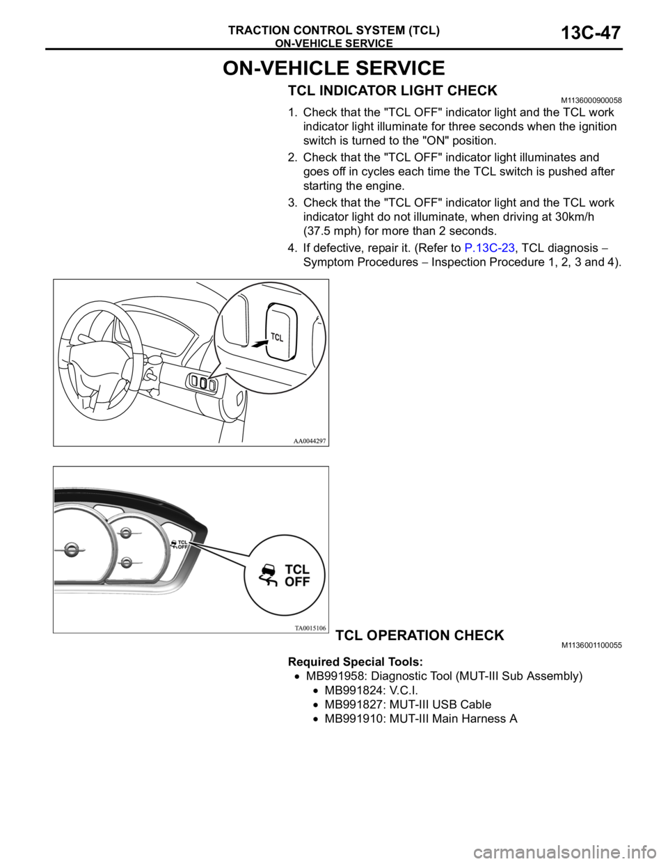
TCL INDICATOR LIGHT CHECKM1136000900058
1. Check that the "TCL OFF" indicator light and the TCL work
indicator light illuminate for three seconds when the ignition
switch is turned to the "ON" position.
2. Check that the "TCL OFF" indicator light illuminates and
goes off in cycles each time the TCL switch is pushed after
starting the engine.
3. Check that the "TCL OFF" indicator light and the TCL work
indicator light do not illuminate, when driving at 30km/h
(37.5 mph) for more than 2 seconds.
4. If defective, repair it. (Refer to P.13C-23, TCL diagnosis
Symptom Procedures
Inspection Procedure 1, 2, 3 and 4).
TCL OPERATION CHECKM1136001100055
Required Special Tools:
MB991958: Diagnostic Tool (MUT-III Sub Assembly)
MB991824: V.C.I.
MB991827: MUT-III USB Cable
MB991910: MUT-III Main Harness A
Page 1393 of 1500
AUTO-CRUISE CONTROL
ENGINE AND EMISSION CONTROL17-62
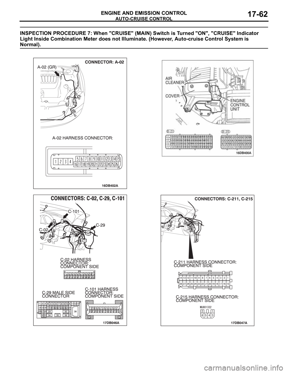
INSPECTION PROCEDURE 7: When "CRUISE" (MAIN) Switch is Turned "ON", "CRUISE" Indicator
Light Inside Combination Meter does not Illuminate. (However, Auto-cruise Control System is
Normal).
.
Page 1396 of 1500

AUTO-CRUISE CONTROL
ENGINE AND EMISSION CONTROL17-65
DATA LIST REFERENCE TABLE - Auto Cruise ControlM1172002400471
When shifting the selector lever to "D" range, apply the brakes so that the vehicle does not move
forward.
Driving tests always need two persons: one driver and one observer.
NOTE: *:After the inspection is completed, disconnect the throttle position sensor connector, and then delete
the diagnostic trouble code using use of Diagnostic Tool MB991958. (Refer to P.17-11).
MUT-III
Diagnostic
To o l
DISPLAYITEM
NO.INSPECTION ITEM INSPECTION REQUIREMENT NORMAL
CONDITION
APS
SNS(MAIN)11 A c c e l e r a t o r p e d a l
position sensor (main)Ignition
switch:
"ON"Accelerator pedal: Released
435
1,035 mV
Accelerator pedal: Gradually
depressedIncreases in
response to the
pedal depression
stroke
Accelerator pedal: Fully
depressed4,000 mV or more
BRAKE SW 89 Stoplamp switch Brake pedal: Depressed ON
Brake pedal: Released OFF
CANCEL
CODE57 Cancel code Ignition switch: "ON" The cancel code,
which set when the
auto-cruise control
system was
cancelled at the
last time, is set
again.
CANCEL
SWITCH75 Auto-cruise
control
switchCANCEL "CANCEL" switch: ON ON
"CANCEL" switch: OFF OFF
CLUTCH SW 78 Transmission inhibitor
switchTransmission inhibitor switch: "P" or
"N"ON
Transmission inhibitor switch: Other
than aboveOFF
CRUISE 81 Auto-cruise control
system operationAuto-cruise control system: active ON
Auto-cruise control system: Inactive OFF
MAIN SW 86 Auto-cruise
control
switchCRUISE
(MAIN)"CRUISE" (MAIN) switch: "ON" ON
"CRUISE" (MAIN) switch: "OFF" OFF
RESUME
SWITCH91 Auto-cruise
control
switchACC/RES "ACC/RES" switch: ON ON
"ACC/RES" switch: OFF OFF
SET SWITCH 92 Auto-cruise
control
switchCOAST/S
ET"COAST/SET" switch: ON ON
"COAST/SET" switch: OFF OFF
STOPLIGHT
SW74 Stoplamp switch Brake pedal: Depressed ON
Brake pedal: Released OFF
Page 1399 of 1500

AUTO-CRUISE CONTROL
ENGINE AND EMISSION CONTROL17-68
If the air intake duct is removed from the throttle body take great care to keep fingers away
from the throttle plate. The drive motor has very high torque and is capable of random move-
ment at any time. Do not under any circumstances activate the throttle plate by hand.
When removing the throttle body from the intake manifold disconnect the wiring first. During
replacement connect the wiring last.
Do not activate the throttle body using a DC suppy to test the motor,as permanent damage to
the throttle body will result.
10 (B-20) Throttle position
sensor power supplyIgnition switch: "ON" 4.9 5.1 V
57 (B-20) Throttle position
sensor (sub)(1) Accelerator pedal:
Released
(2) Accelerator pedal:
Depressed(1) Throttle
valve fully
closed1035
1250 mV
(2) Throttle
valve fully open4000 mV or more
42 (B-20) Throttle position
sensor (main)(1) Accelerator pedal:
Released
(2) Accelerator pedal:
Depressed(1) Throttle
valve fully
closed1035
1250 mV
(2) Throttle
valve fully open4000 mV or more
49 (B-20) Throttle actuator
control motor (
)
Ignition switch: "ON"
Accelerator pedal: fully closed to fully
openedDecreases slightly
(approx. 2 V) from
battery voltage.
50 (B-20) Throttle actuator
control motor (+)
Ignition switch: "ON"
Accelerator pedal: fully opened to fully
closedDecreases slightly
(approx. 2 V) from
battery voltage. TERMINAL
NO.CHECK ITEM CHECK CONDITION NORMAL
CONDITION
Page 1404 of 1500
AUTO-CRUISE CONTROL
ENGINE AND EMISSION CONTROL17-73
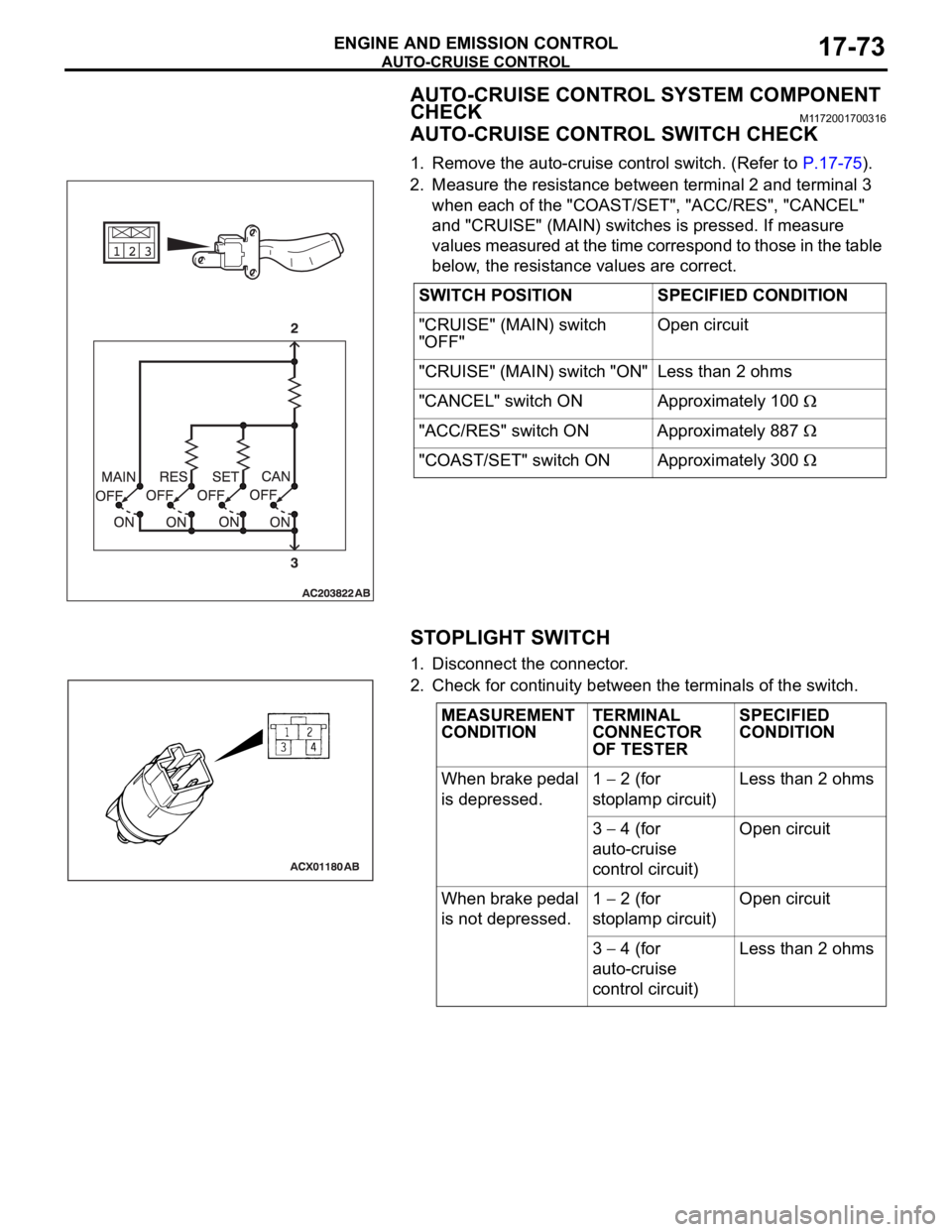
AUTO-CRUISE CONTROL SYSTEM COMPONENT
CHECK
M1172001700316
AUTO-CRUISE CONTROL SWITCH CHECK
1. Remove the auto-cruise control switch. (Refer to P.17-75).
2. Measure the resistance between terminal 2 and terminal 3
when each of the "COAST/SET", "ACC/RES", "CANCEL"
and "CRUISE" (MAIN) switches is pressed. If measure
values measured at the time correspond to those in the table
below, the resistance values are correct.
STOPLIGHT SWITCH
1. Disconnect the connector.
2. Check for continuity between the terminals of the switch.SWITCH POSITION SPECIFIED CONDITION
"CRUISE" (MAIN) switch
"OFF"Open circuit
"CRUISE" (MAIN) switch "ON" Less than 2 ohms
"CANCEL" switch ON Approximately 100
"ACC/RES" switch ON Approximately 887
"COAST/SET" switch ON Approximately 300
MEASUREMENT
CONDITIONTERMINAL
CONNECTOR
OF TESTERSPECIFIED
CONDITION
When brake pedal
is depressed.1
2 (for
stoplamp circuit)Less than 2 ohms
3
4 (for
auto-cruise
control circuit)Open circuit
When brake pedal
is not depressed.1
2 (for
stoplamp circuit)Open circuit
3
4 (for
auto-cruise
control circuit)Less than 2 ohms
Page 1406 of 1500
AUTO-CRUISE CONTROL
ENGINE AND EMISSION CONTROL17-75
AUTO-CRUISE CONTROL
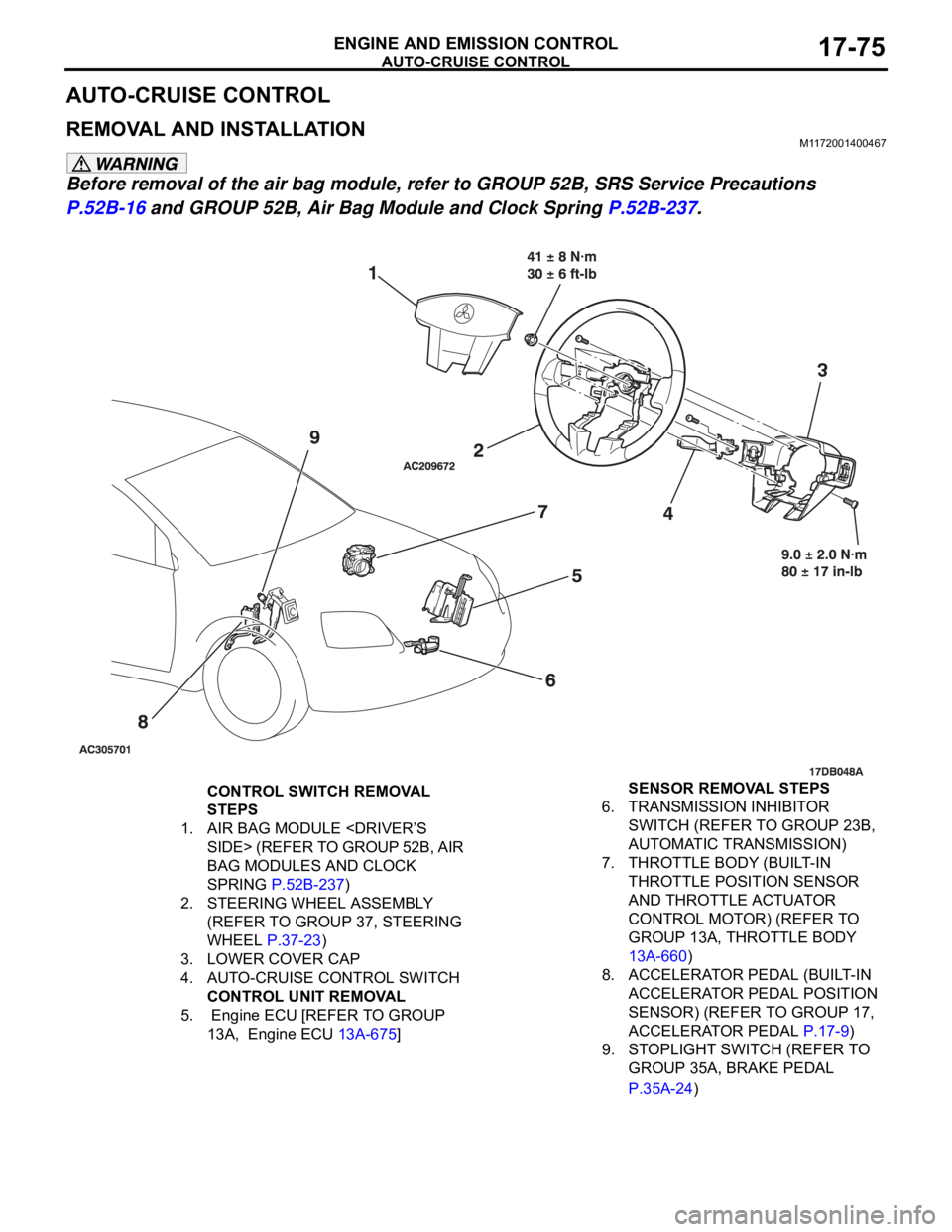
REMOVAL AND INSTALLATIONM1172001400467
Before removal of the air bag module, refer to GROUP 52B, SRS Service Precautions
P.52B-16 and GROUP 52B, Air Bag Module and Clock Spring P.52B-237.
CONTROL SWITCH REMOVAL
STEPS
1. AIR BAG MODULE
BAG MODULES AND CLOCK
SPRING P.52B-237)
2. STEERING WHEEL ASSEMBLY
(REFER TO GROUP 37, STEERING
WHEEL P.37-23)
3. LOWER COVER CAP
4. AUTO-CRUISE CONTROL SWITCH
CONTROL UNIT REMOVAL
5. Engine ECU [REFER TO GROUP
13A, Engine ECU 13A-675] SENSOR REMOVAL STEPS
6. TRANSMISSION INHIBITOR
SWITCH (REFER TO GROUP 23B,
AUTOMATIC TRANSMISSION)
7. THROTTLE BODY (BUILT-IN
THROTTLE POSITION SENSOR
AND THROTTLE ACTUATOR
CONTROL MOTOR) (REFER TO
GROUP 13A, THROTTLE BODY
13A-660)
8. ACCELERATOR PEDAL (BUILT-IN
ACCELERATOR PEDAL POSITION
SENSOR) (REFER TO GROUP 17,
ACCELERATOR PEDAL P.17-9)
9. STOPLIGHT SWITCH (REFER TO
GROUP 35A, BRAKE PEDAL
P.35A-24)
Page 1414 of 1500
EMISSION CONTROL
ENGINE AND EMISSION CONTROL17-83
Required Special Tool:
MB995061: Purge Flow Indicator
1. Disconnect the purge hose from the evaporative emission
(EVAP) purge solenoid, and connect special tool MB995061
between the EVAP purge solenoid and the purge hose.
2. Before inspection, set the vehicle in the following conditions:
Engine coolant temperature: 80 95C (176 203F)
Lights, electric cooling fan and accessories: OFF
Transaxle: P range
3. Run the engine at idle for more than four minutes.
4. Check the purge flow volume when engine is revved
suddenly several times.
Standard value: Momentarily 20 cm
3/s (2.5 SCFH) or
more.
5. If the purge flow volume is less than the standard value,
check it again with the vacuum hose disconnected from the
EVAP canister. If the purge flow volume is less than the
standard value, check the vacuum port and the vacuum
hose for clogging. Also check the EVAP purge solenoid. If
the purge flow volume is at the standard value, replace the
EVAP canister.
EVAPORATIVE EMISSION PURGE SOLENOID
CHECK
M1173001700289
1. Disconnect the vacuum hose (black, black with red paint
mark) from the evaporative emission (EVAP) purge
solenoid.
NOTE: When disconnecting the vacuum hose, always place
an identification mark so that it can be reconnected at its
original position.
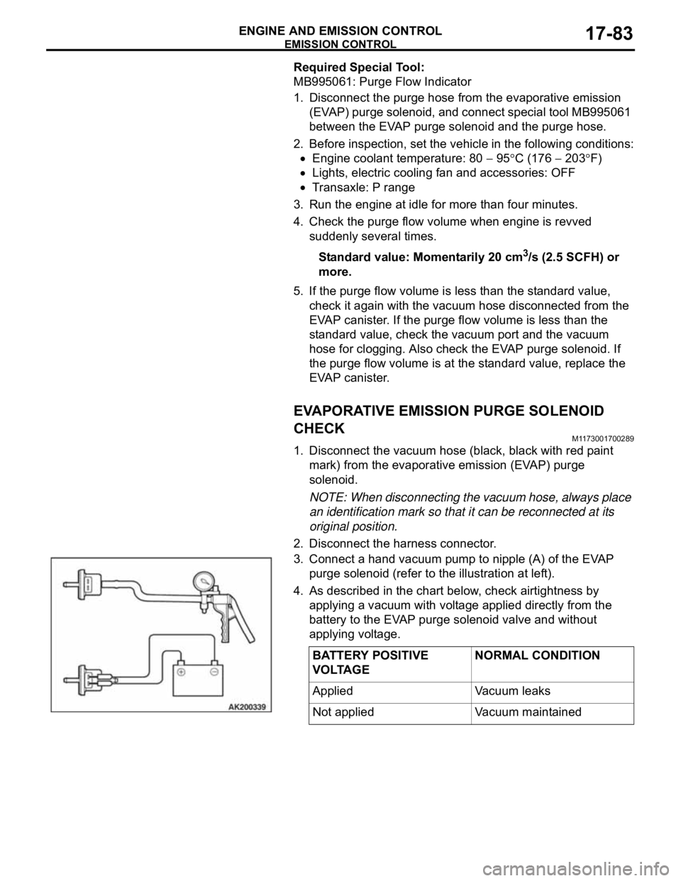
2. Disconnect the harness connector.
3. Connect a hand vacuum pump to nipple (A) of the EVAP
purge solenoid (refer to the illustration at left).
4. As described in the chart below, check airtightness by
applying a vacuum with voltage applied directly from the
battery to the EVAP purge solenoid valve and without
applying voltage.
BATTERY POSITIVE
VOLTAGENORMAL CONDITION
Applied Vacuum leaks
Not applied Vacuum maintained