Ignition MITSUBISHI 380 2005 Workshop Manual
[x] Cancel search | Manufacturer: MITSUBISHI, Model Year: 2005, Model line: 380, Model: MITSUBISHI 380 2005Pages: 1500, PDF Size: 47.87 MB
Page 253 of 1500
SYMPTOM PROCEDURES
SIMPLIFIED WIRING SYSTEM (SWS)54B-253
STEP 3. Check the input signal by using "FUNCTION
DIAG." menu of the SWS monitor.
Check the input signals from the following switches:
Ignition switch: ACC
Windshield washer switch: ON
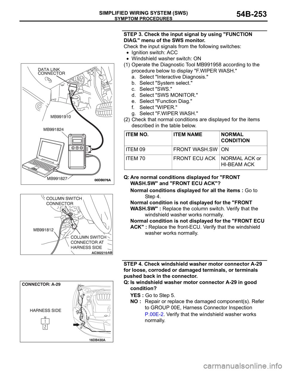
(1) Operate the Diagnostic Tool MB991958 according to the
procedure below to display "F.WIPER WASH."
a. Select "Interactive Diagnosis."
b. Select "System select."
c. Select "SWS."
d. Select "SWS MONITOR."
e. Select "Function Diag."
f. Select "WIPER."
g. Select "F.WIPER WASH."
(2) Check that normal conditions are displayed for the items
described in the table below.
Q: Are normal conditions displayed for "FRONT
WASH.SW" and "FRONT ECU ACK"?
Normal conditions displayed for all the items : Go to
St e p 4 .
Normal condition is not displayed for the "FRONT
WASH.SW" : Replace the column switch. Verify that the
windshield washer works normally.
Normal condition is not displayed for the "FRONT ECU
ACK" : Replace the front-ECU. Verify that the windshield
washer works normally.
STEP 4. Check windshield washer motor connector A-29
for loose, corroded or damaged terminals, or terminals
pushed back in the connector.
Q: Is windshield washer motor connector A-29 in good
condition?
YES : Go to Step 5.
NO : Repair or replace the damaged component(s). Refer
to GROUP 00E, Harness Connector Inspection
P.00E-2. Verify that the windshield washer works
normally. ITEM NO. ITEM NAME NORMAL
CONDITION
ITEM 09 FRONT WASH.SW ON
ITEM 70 FRONT ECU ACK NORMAL ACK or
HI-BEAM ACK
Page 259 of 1500
SYMPTOM PROCEDURES
SIMPLIFIED WIRING SYSTEM (SWS)54B-259
Headlamp automatic-shutdown function
Even if the lighting switch (taillamps switch or headlamp switch)
is ON, the headlamps (including the taillamps) will automati-
cally go off in the following conditions to prevent the battery
from discharging as a result of forgetting to turn off lamps.
If the ignition key is turned from "ON" to "LOCK" (OFF) or
"ACC" position with the lighting switch turned ON, and this
state continues for three minutes, the headlamps will automati-
cally be turned off. If the driver's seat door is opened during
these three minutes, the headlamps will go off one second
later.
NOTE: The headlamp automatic-shutoff function can be cus-
tomized on vehicles equipped with a multi center display (mid-
dle grade type). Refer to P.54B-486.
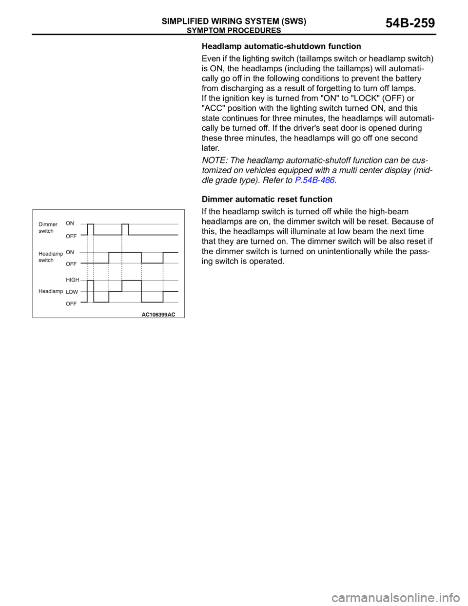
Dimmer automatic reset function
If the headlamp switch is turned off while the high-beam
headlamps are on, the dimmer switch will be reset. Because of
this, the headlamps will illuminate at low beam the next time
that they are turned on. The dimmer switch will be also reset if
the dimmer switch is turned on unintentionally while the pass-
ing switch is operated.
Page 261 of 1500
SYMPTOM PROCEDURES
SIMPLIFIED WIRING SYSTEM (SWS)54B-261
STEP 1. Use Diagnostic Tool MB991958 to select "ECU
COMM Check" on the SWS monitor display.
Check the following ECUs:
Column switch (column-ECU)
Front-ECU
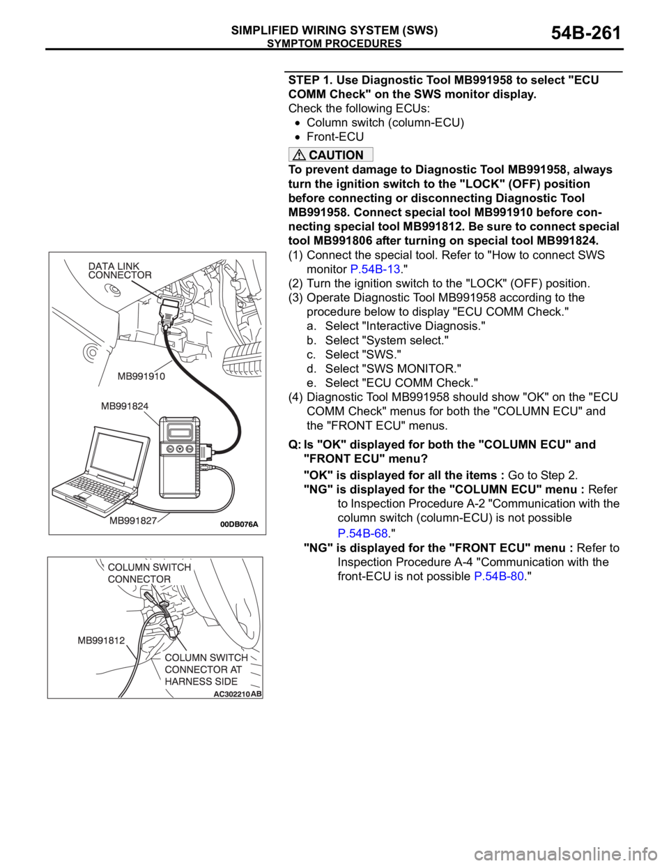
To prevent damage to Diagnostic Tool MB991958, always
turn the ignition switch to the "LOCK" (OFF) position
before connecting or disconnecting Diagnostic Tool
MB991958. Connect special tool MB991910 before con-
necting special tool MB991812. Be sure to connect special
tool MB991806 after turning on special tool MB991824.
(1) Connect the special tool. Refer to "How to connect SWS
monitor P.54B-13."
(2) Turn the ignition switch to the "LOCK" (OFF) position.
(3) Operate Diagnostic Tool MB991958 according to the
procedure below to display "ECU COMM Check."
a. Select "Interactive Diagnosis."
b. Select "System select."
c. Select "SWS."
d. Select "SWS MONITOR."
e. Select "ECU COMM Check."
(4) Diagnostic Tool MB991958 should show "OK" on the "ECU
COMM Check" menus for both the "COLUMN ECU" and
the "FRONT ECU" menus.
Q: Is "OK" displayed for both the "COLUMN ECU" and
"FRONT ECU" menu?
"OK" is displayed for all the items : Go to Step 2.
"NG" is displayed for the "COLUMN ECU" menu : Refer
to Inspection Procedure A-2 "Communication with the
column switch (column-ECU) is not possible
P.54B-68."
"NG" is displayed for the "FRONT ECU" menu : Refer to
Inspection Procedure A-4 "Communication with the
front-ECU is not possible P.54B-80."
Page 262 of 1500
SYMPTOM PROCEDURES
SIMPLIFIED WIRING SYSTEM (SWS)54B-262
STEP 2. Check the input signal by using "FUNCTION
DIAG." menu of the SWS monitor.
Check the input signals from the following switches:
Ignition switch: ON
Lighting switch: TAIL
NOTE: Turn the ignition switch to the "ON" position in order to
disable the headlamp automatic shutdown function.
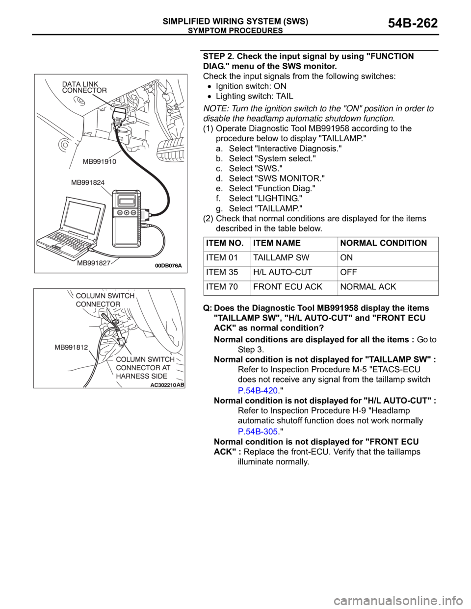
(1) Operate Diagnostic Tool MB991958 according to the
procedure below to display "TAILLAMP."
a. Select "Interactive Diagnosis."
b. Select "System select."
c. Select "SWS."
d. Select "SWS MONITOR."
e. Select "Function Diag."
f. Select "LIGHTING."
g. Select "TAILLAMP."
(2) Check that normal conditions are displayed for the items
described in the table below.
Q: Does the Diagnostic Tool MB991958 display the items
"TAILLAMP SW", "H/L AUTO-CUT" and "FRONT ECU
ACK" as normal condition?
Normal conditions are displayed for all the items : Go to
St e p 3 .
Normal condition is not displayed for "TAILLAMP SW" :
Refer to Inspection Procedure M-5 "ETACS-ECU
does not receive any signal from the taillamp switch
P.54B-420."
Normal condition is not displayed for "H/L AUTO-CUT" :
Refer to Inspection Procedure H-9 "Headlamp
automatic shutoff function does not work normally
P.54B-305."
Normal condition is not displayed for "FRONT ECU
ACK" : Replace the front-ECU. Verify that the taillamps
illuminate normally. ITEM NO. ITEM NAME NORMAL CONDITION
ITEM 01 TAILLAMP SW ON
ITEM 35 H/L AUTO-CUT OFF
ITEM 70 FRONT ECU ACK NORMAL ACK
Page 265 of 1500
SYMPTOM PROCEDURES
SIMPLIFIED WIRING SYSTEM (SWS)54B-265
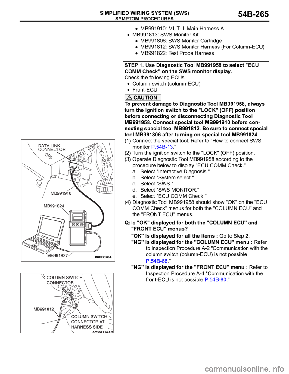
MB991910: MUT-III Main Harness A
MB991813: SWS Monitor Kit
MB991806: SWS Monitor Cartridge
MB991812: SWS Monitor Harness (For Column-ECU)
MB991822: Test Probe Harness
STEP 1. Use Diagnostic Tool MB991958 to select "ECU
COMM Check" on the SWS monitor display.
Check the following ECUs:
Column switch (column-ECU)
Front-ECU
To prevent damage to Diagnostic Tool MB991958, always
turn the ignition switch to the "LOCK" (OFF) position
before connecting or disconnecting Diagnostic Tool
MB991958. Connect special tool MB991910 before con-
necting special tool MB991812. Be sure to connect special
tool MB991806 after turning on special tool MB991824.
(1) Connect the special tool. Refer to "How to connect SWS
monitor P.54B-13."
(2) Turn the ignition switch to the "LOCK" (OFF) position.
(3) Operate Diagnostic Tool MB991958 according to the
procedure below to display "ECU COMM Check."
a. Select "Interactive Diagnosis."
b. Select "System select."
c. Select "SWS."
d. Select "SWS MONITOR."
e. Select "ECU COMM Check."
(4) Diagnostic Tool MB991958 should show "OK" on the "ECU
COMM Check" menus for both the "COLUMN ECU" and
the "FRONT ECU" menus.
Q: Is "OK" displayed for both the "COLUMN ECU" and
"FRONT ECU" menus?
"OK" is displayed for all the items : Go to Step 2.
"NG" is displayed for the "COLUMN ECU" menu : Refer
to Inspection Procedure A-2 "Communication with the
column switch (column-ECU) is not possible
P.54B-68."
"NG" is displayed for the "FRONT ECU" menu : Refer to
Inspection Procedure A-4 "Communication with the
front-ECU is not possible P.54B-80."
Page 266 of 1500
SYMPTOM PROCEDURES
SIMPLIFIED WIRING SYSTEM (SWS)54B-266
STEP 2. Check the input signal by using "FUNCTION
DIAG." menu of the SWS monitor.
Check the input signals from the following switches:
Ignition switch: ON
Lighting switch: HEAD
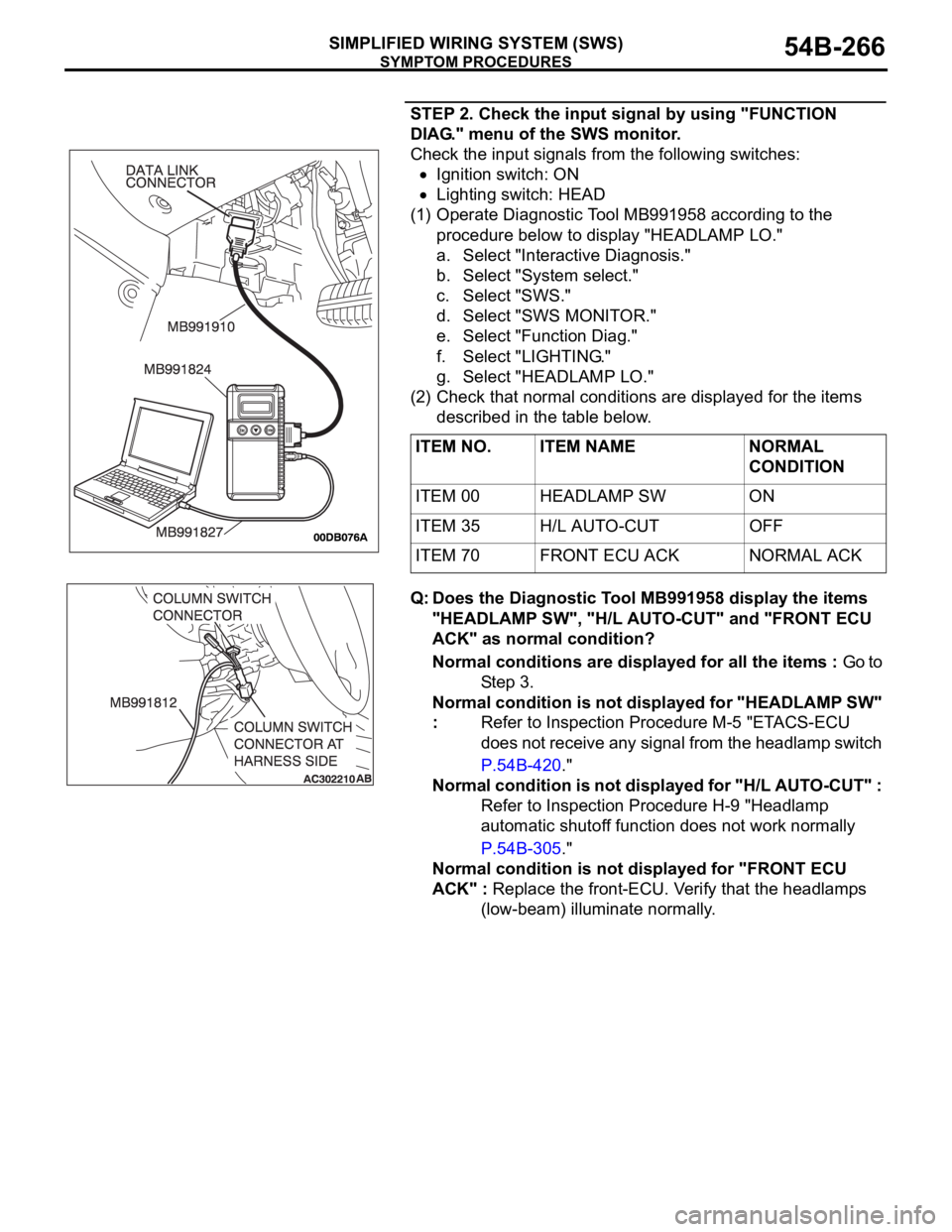
(1) Operate Diagnostic Tool MB991958 according to the
procedure below to display "HEADLAMP LO."
a. Select "Interactive Diagnosis."
b. Select "System select."
c. Select "SWS."
d. Select "SWS MONITOR."
e. Select "Function Diag."
f. Select "LIGHTING."
g. Select "HEADLAMP LO."
(2) Check that normal conditions are displayed for the items
described in the table below.
Q: Does the Diagnostic Tool MB991958 display the items
"HEADLAMP SW", "H/L AUTO-CUT" and "FRONT ECU
ACK" as normal condition?
Normal conditions are displayed for all the items : Go to
St e p 3 .
Normal condition is not displayed for "HEADLAMP SW"
: Refer to Inspection Procedure M-5 "ETACS-ECU
does not receive any signal from the headlamp switch
P.54B-420."
Normal condition is not displayed for "H/L AUTO-CUT" :
Refer to Inspection Procedure H-9 "Headlamp
automatic shutoff function does not work normally
P.54B-305."
Normal condition is not displayed for "FRONT ECU
ACK" : Replace the front-ECU. Verify that the headlamps
(low-beam) illuminate normally. ITEM NO. ITEM NAME NORMAL
CONDITION
ITEM 00 HEADLAMP SW ON
ITEM 35 H/L AUTO-CUT OFF
ITEM 70 FRONT ECU ACK NORMAL ACK
Page 269 of 1500
SYMPTOM PROCEDURES
SIMPLIFIED WIRING SYSTEM (SWS)54B-269
STEP 1. Use Diagnostic Tool MB991958 to select "ECU
COMM Check" on the SWS monitor display.
Check the following ECUs:
Column switch (column-ECU)
Front-ECU
To prevent damage to Diagnostic Tool MB991958, always
turn the ignition switch to the "LOCK" (OFF) position
before connecting or disconnecting Diagnostic Tool
MB991958. Connect special tool MB991910 before con-
necting special tool MB991812. Be sure to connect special
tool MB991806 after turning on special tool MB991824.
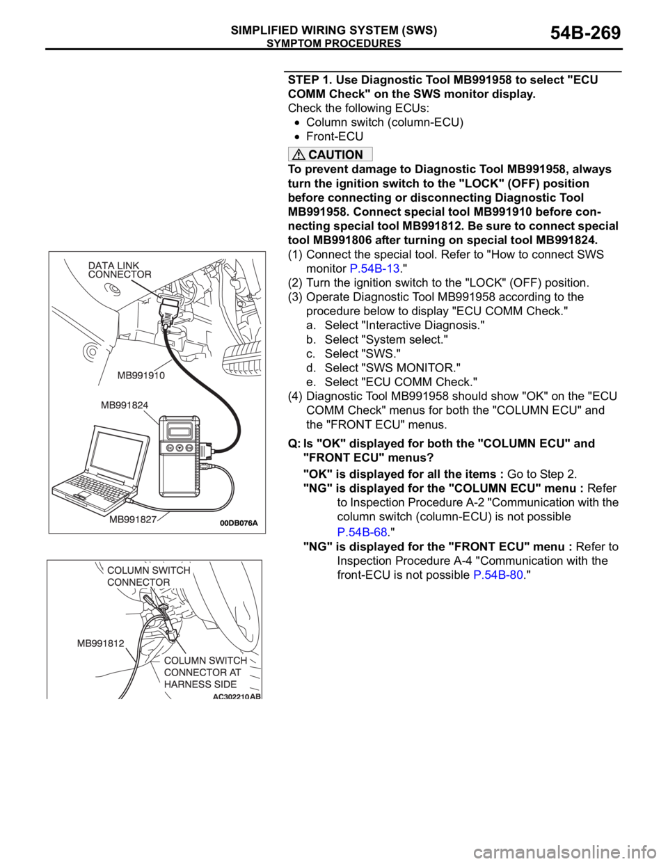
(1) Connect the special tool. Refer to "How to connect SWS
monitor P.54B-13."
(2) Turn the ignition switch to the "LOCK" (OFF) position.
(3) Operate Diagnostic Tool MB991958 according to the
procedure below to display "ECU COMM Check."
a. Select "Interactive Diagnosis."
b. Select "System select."
c. Select "SWS."
d. Select "SWS MONITOR."
e. Select "ECU COMM Check."
(4) Diagnostic Tool MB991958 should show "OK" on the "ECU
COMM Check" menus for both the "COLUMN ECU" and
the "FRONT ECU" menus.
Q: Is "OK" displayed for both the "COLUMN ECU" and
"FRONT ECU" menus?
"OK" is displayed for all the items : Go to Step 2.
"NG" is displayed for the "COLUMN ECU" menu : Refer
to Inspection Procedure A-2 "Communication with the
column switch (column-ECU) is not possible
P.54B-68."
"NG" is displayed for the "FRONT ECU" menu : Refer to
Inspection Procedure A-4 "Communication with the
front-ECU is not possible P.54B-80."
Page 270 of 1500
SYMPTOM PROCEDURES
SIMPLIFIED WIRING SYSTEM (SWS)54B-270
STEP 2. Check the input signal by using "FUNCTION
DIAG." menu of the SWS monitor.
Check the input signals from the following switches:
Ignition switch: ON
Lighting switch: HEAD
Dimmer switch: ON
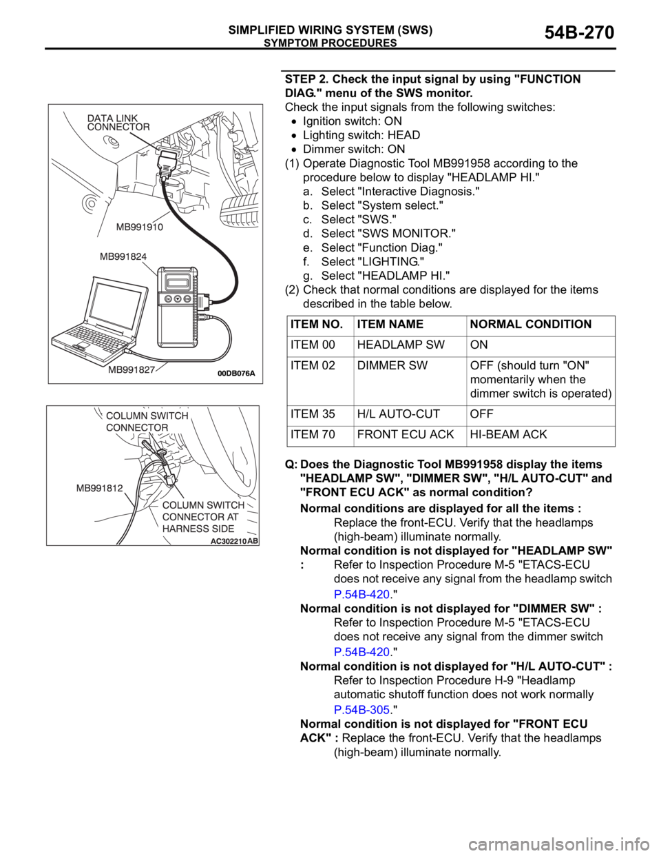
(1) Operate Diagnostic Tool MB991958 according to the
procedure below to display "HEADLAMP HI."
a. Select "Interactive Diagnosis."
b. Select "System select."
c. Select "SWS."
d. Select "SWS MONITOR."
e. Select "Function Diag."
f. Select "LIGHTING."
g. Select "HEADLAMP HI."
(2) Check that normal conditions are displayed for the items
described in the table below.
Q: Does the Diagnostic Tool MB991958 display the items
"HEADLAMP SW", "DIMMER SW", "H/L AUTO-CUT" and
"FRONT ECU ACK" as normal condition?
Normal conditions are displayed for all the items :
Replace the front-ECU. Verify that the headlamps
(high-beam) illuminate normally.
Normal condition is not displayed for "HEADLAMP SW"
: Refer to Inspection Procedure M-5 "ETACS-ECU
does not receive any signal from the headlamp switch
P.54B-420."
Normal condition is not displayed for "DIMMER SW" :
Refer to Inspection Procedure M-5 "ETACS-ECU
does not receive any signal from the dimmer switch
P.54B-420."
Normal condition is not displayed for "H/L AUTO-CUT" :
Refer to Inspection Procedure H-9 "Headlamp
automatic shutoff function does not work normally
P.54B-305."
Normal condition is not displayed for "FRONT ECU
ACK" : Replace the front-ECU. Verify that the headlamps
(high-beam) illuminate normally. ITEM NO. ITEM NAME NORMAL CONDITION
ITEM 00 HEADLAMP SW ON
ITEM 02 DIMMER SW OFF (should turn "ON"
momentarily when the
dimmer switch is operated)
ITEM 35 H/L AUTO-CUT OFF
ITEM 70 FRONT ECU ACK HI-BEAM ACK
Page 272 of 1500
SYMPTOM PROCEDURES
SIMPLIFIED WIRING SYSTEM (SWS)54B-272
STEP 2. Check the input signal by using "DATA LIST"
menu of the SWS monitor.
Turn the passing switch to the "ON" position before checking
input signals from the passing switch.
To prevent damage to Diagnostic Tool MB991958, always
turn the ignition switch to the "LOCK" (OFF) position
before connecting or disconnecting Diagnostic Tool
MB991958. Connect special tool MB991910 before con-
necting special tool MB991812. Be sure to connect special
tool MB991806 after turning on special tool MB991824.
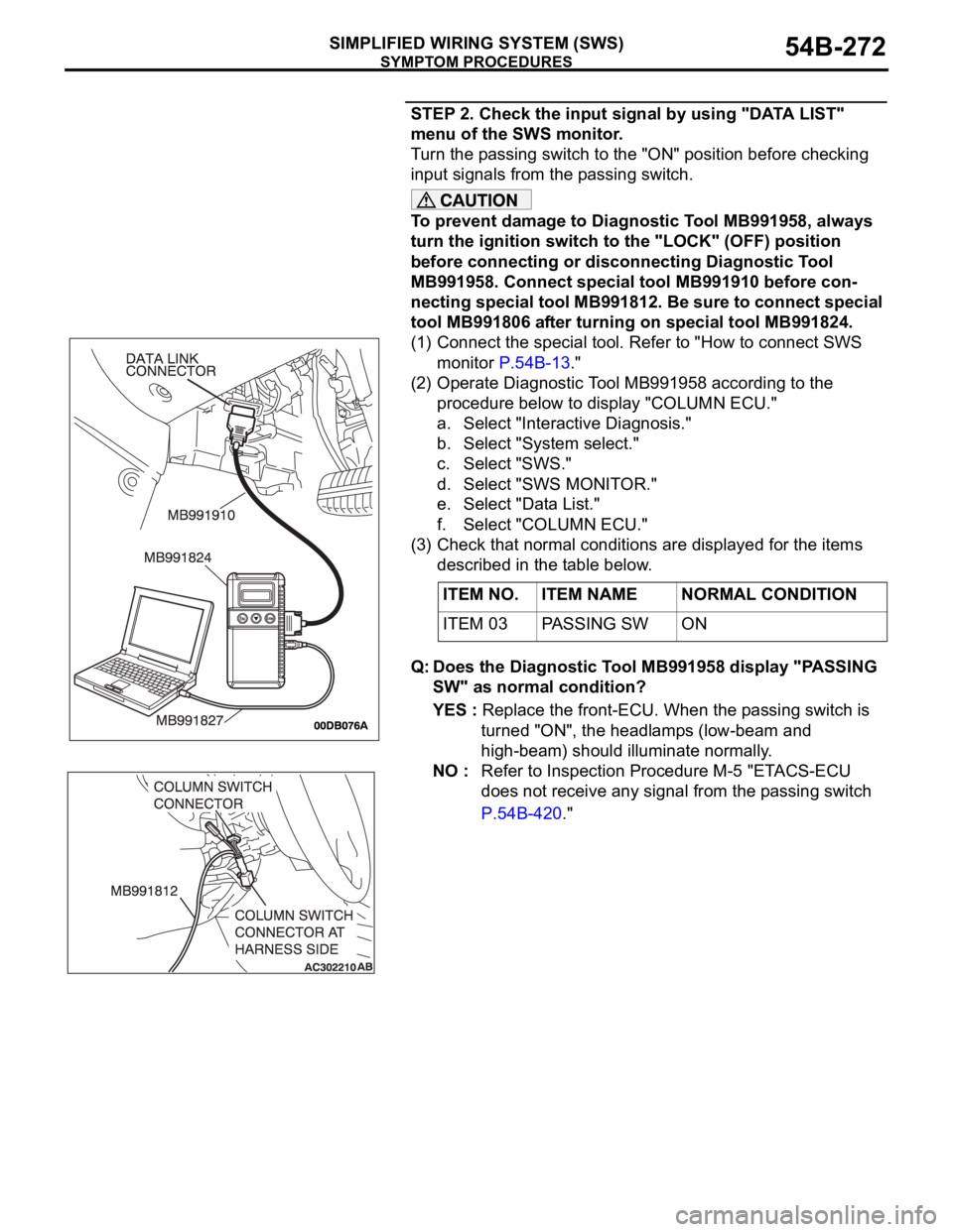
(1) Connect the special tool. Refer to "How to connect SWS
monitor P.54B-13."
(2) Operate Diagnostic Tool MB991958 according to the
procedure below to display "COLUMN ECU."
a. Select "Interactive Diagnosis."
b. Select "System select."
c. Select "SWS."
d. Select "SWS MONITOR."
e. Select "Data List."
f. Select "COLUMN ECU."
(3) Check that normal conditions are displayed for the items
described in the table below.
Q: Does the Diagnostic Tool MB991958 display "PASSING
SW" as normal condition?
YES : Replace the front-ECU. When the passing switch is
turned "ON", the headlamps (low-beam and
high-beam) should illuminate normally.
NO : Refer to Inspection Procedure M-5 "ETACS-ECU
does not receive any signal from the passing switch
P.54B-420." ITEM NO. ITEM NAME NORMAL CONDITION
ITEM 03 PASSING SW ON
Page 274 of 1500
SYMPTOM PROCEDURES
SIMPLIFIED WIRING SYSTEM (SWS)54B-274
Use Diagnostic Tool MB991958 to select "ECU COMM
Check" on the SWS monitor display.
Check the following ECUs:
ETACS-ECU
Column-ECU
Front-ECU
To prevent damage to Diagnostic Tool MB991958, always
turn the ignition switch to the "LOCK" (OFF) position
before connecting or disconnecting Diagnostic Tool
MB991958. Connect special tool MB991910 before con-
necting special tool MB991812. Be sure to connect special
tool MB991806 after turning on special tool MB991824.
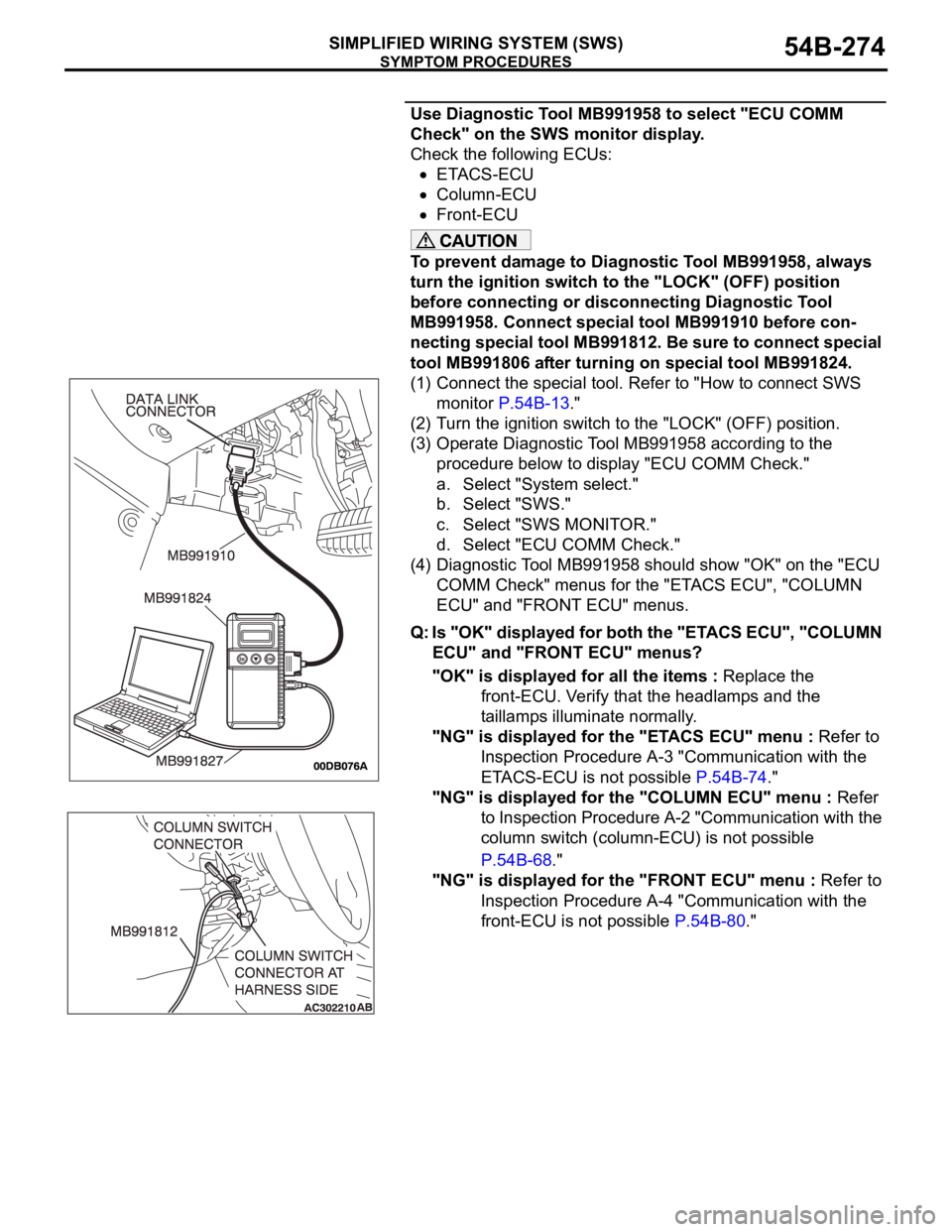
(1) Connect the special tool. Refer to "How to connect SWS
monitor P.54B-13."
(2) Turn the ignition switch to the "LOCK" (OFF) position.
(3) Operate Diagnostic Tool MB991958 according to the
procedure below to display "ECU COMM Check."
a. Select "System select."
b. Select "SWS."
c. Select "SWS MONITOR."
d. Select "ECU COMM Check."
(4) Diagnostic Tool MB991958 should show "OK" on the "ECU
COMM Check" menus for the "ETACS ECU", "COLUMN
ECU" and "FRONT ECU" menus.
Q: Is "OK" displayed for both the "ETACS ECU", "COLUMN
ECU" and "FRONT ECU" menus?
"OK" is displayed for all the items : Replace the
front-ECU. Verify that the headlamps and the
taillamps illuminate normally.
"NG" is displayed for the "ETACS ECU" menu : Refer to
Inspection Procedure A-3 "Communication with the
ETACS-ECU is not possible P.54B-74."
"NG" is displayed for the "COLUMN ECU" menu : Refer
to Inspection Procedure A-2 "Communication with the
column switch (column-ECU) is not possible
P.54B-68."
"NG" is displayed for the "FRONT ECU" menu : Refer to
Inspection Procedure A-4 "Communication with the
front-ECU is not possible P.54B-80."