sensor MITSUBISHI 380 2005 Workshop Manual
[x] Cancel search | Manufacturer: MITSUBISHI, Model Year: 2005, Model line: 380, Model: MITSUBISHI 380 2005Pages: 1500, PDF Size: 47.87 MB
Page 1398 of 1500
AUTO-CRUISE CONTROL
ENGINE AND EMISSION CONTROL17-67
ENGINE ECU TERMINAL VOLTAGE REFERENCE CHART FOR AUTO-CRUISE
CONTROL SYSTEM OPERATION
M1172004800055
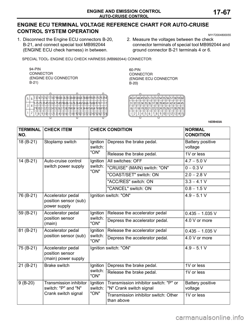
1. Disconnect the Engine ECU connectors B-20,
B-21, and connect special tool MB992044
(ENGINE ECU check harness) in between.2. Measure the voltages between the check
connector terminals of special tool MB992044 and
ground connector B-21 terminals 4 or 6.
TERMINAL
NO.CHECK ITEM CHECK CONDITION NORMAL
CONDITION
18 (B-21) Stoplamp switch Ignition
switch:
"ON"Depress the brake pedal. Battery positive
voltage
Release the brake pedal. 1V or less
14 (B-21) Auto-cruise control
switch power supplyIgnition
switch:
"ON"All switches: OFF 4.7
5.0 V
"CRUISE" (MAIN) switch: "ON" 0
0.3 V
"COAST/SET" switch: ON 2.0
2.8 V
"ACC/RES" switch: ON 3.3
4.1 V
"CANCEL" switch: ON 0.8
1.5 V
76 (B-21) Accelerator pedal
position sensor (sub)
power supplyIgnition switch: "ON" 4.9
5.1 V
59 (B-21) Accelerator pedal
position sensor
(main)Ignition
switch:
"ON"Release the accelerator pedal
0.435
1.035 V
Depress the accelerator pedal. 4.0 V or more
81 (B-21) Accelerator pedal
position sensor (sub)Ignition
switch:
"ON"Release the accelerator pedal
0.435
1.035 V
Depress the accelerator pedal. 4.0 V or more
75 (B-21) Accelerator pedal
position sensor
(main) power supplyIgnition switch: "ON" 4.9
5.1 V
21 (B-21) Brake switch Ignition
switch:
"ON"Depress the brake pedal. 1V or less
Release the brake pedal. 1V or less
9 (B-20) Transmission inhibitor
switch: "P" and "N"
Crank switch signalIgnition
switch:
"ON"Transmission inhibitor switch: "P" or
"N" Crank switch signalBattery positive
voltage
Transmission inhibitor switch: Other
than above1V or less
Page 1399 of 1500

AUTO-CRUISE CONTROL
ENGINE AND EMISSION CONTROL17-68
If the air intake duct is removed from the throttle body take great care to keep fingers away
from the throttle plate. The drive motor has very high torque and is capable of random move-
ment at any time. Do not under any circumstances activate the throttle plate by hand.
When removing the throttle body from the intake manifold disconnect the wiring first. During
replacement connect the wiring last.
Do not activate the throttle body using a DC suppy to test the motor,as permanent damage to
the throttle body will result.
10 (B-20) Throttle position
sensor power supplyIgnition switch: "ON" 4.9 5.1 V
57 (B-20) Throttle position
sensor (sub)(1) Accelerator pedal:
Released
(2) Accelerator pedal:
Depressed(1) Throttle
valve fully
closed1035
1250 mV
(2) Throttle
valve fully open4000 mV or more
42 (B-20) Throttle position
sensor (main)(1) Accelerator pedal:
Released
(2) Accelerator pedal:
Depressed(1) Throttle
valve fully
closed1035
1250 mV
(2) Throttle
valve fully open4000 mV or more
49 (B-20) Throttle actuator
control motor (
)
Ignition switch: "ON"
Accelerator pedal: fully closed to fully
openedDecreases slightly
(approx. 2 V) from
battery voltage.
50 (B-20) Throttle actuator
control motor (+)
Ignition switch: "ON"
Accelerator pedal: fully opened to fully
closedDecreases slightly
(approx. 2 V) from
battery voltage. TERMINAL
NO.CHECK ITEM CHECK CONDITION NORMAL
CONDITION
Page 1405 of 1500
AUTO-CRUISE CONTROL
ENGINE AND EMISSION CONTROL17-74
THROTTLE POSITION SENSOR
Refer to GROUP 13A, On-vehicle Service Throttle Actuator
Control Motor Check 13A-671 (3.8L engine).
If the air intake duct is removed from the throttle
body take great care to keep fingers away from the
throttle plate. The drive motor has very high torque
and is capable of random movement at any time. Do
not under any circumstance activate the throttle plate
by hand.
When removing the throttle body from the intake
manifold disconnect the wiring first.During replace-
ment connect the wiring last.
Do not activate the throttle body using a DC supply to
test the motor, as permanent damage to the throttle
body will result.
TRANSMISSION INHIBITOR SWITCH ("N"
POSITION)
Refer to GROUP 23A, On-vehicle Service Essential Service
P.23A-294.
Page 1406 of 1500
AUTO-CRUISE CONTROL
ENGINE AND EMISSION CONTROL17-75
AUTO-CRUISE CONTROL
REMOVAL AND INSTALLATIONM1172001400467
Before removal of the air bag module, refer to GROUP 52B, SRS Service Precautions
P.52B-16 and GROUP 52B, Air Bag Module and Clock Spring P.52B-237.
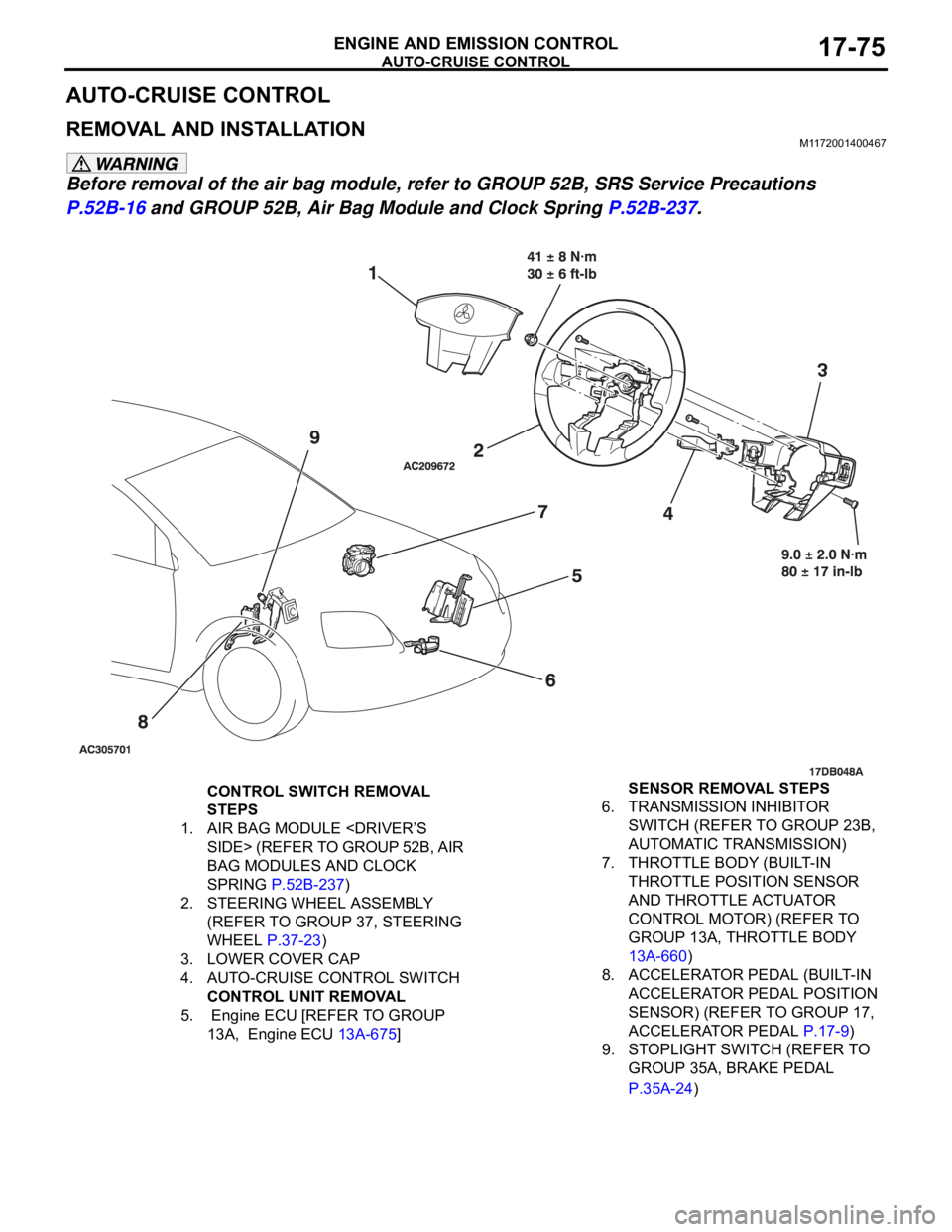
CONTROL SWITCH REMOVAL
STEPS
1. AIR BAG MODULE
BAG MODULES AND CLOCK
SPRING P.52B-237)
2. STEERING WHEEL ASSEMBLY
(REFER TO GROUP 37, STEERING
WHEEL P.37-23)
3. LOWER COVER CAP
4. AUTO-CRUISE CONTROL SWITCH
CONTROL UNIT REMOVAL
5. Engine ECU [REFER TO GROUP
13A, Engine ECU 13A-675] SENSOR REMOVAL STEPS
6. TRANSMISSION INHIBITOR
SWITCH (REFER TO GROUP 23B,
AUTOMATIC TRANSMISSION)
7. THROTTLE BODY (BUILT-IN
THROTTLE POSITION SENSOR
AND THROTTLE ACTUATOR
CONTROL MOTOR) (REFER TO
GROUP 13A, THROTTLE BODY
13A-660)
8. ACCELERATOR PEDAL (BUILT-IN
ACCELERATOR PEDAL POSITION
SENSOR) (REFER TO GROUP 17,
ACCELERATOR PEDAL P.17-9)
9. STOPLIGHT SWITCH (REFER TO
GROUP 35A, BRAKE PEDAL
P.35A-24)
Page 1407 of 1500
EMISSION CONTROL
ENGINE AND EMISSION CONTROL17-76
EMISSION CONTROL
GENERAL DESCRIPTIONM1173000100314
The emission control system consists of the fol-
lowing subsystems:
Positive crankcase ventilation system
Evaporative emission system
Exhaust emission control system
DIAGNOSISM1173000700112
SPECIAL TOOLSM1173000600193
SYMPTOM PROBABLE CAUSE REMEDY
Engine will not start or hard
to startVacuum hose disconnected or damaged Repair or replace
Malfunction of the evaporative emission
purge solenoidRepair or replace
Rough idle or engine stalls
Vacuum hose disconnected or damaged. Repair or replace
Malfunction of the positive crankcase
ventilation valveReplace
Malfunction of the purge control system Check the system; If there is a
problem, check its component
parts.
Excessive oil consumption Positive crankcase ventilation line
cloggedCheck positive crankcase
ventilation system
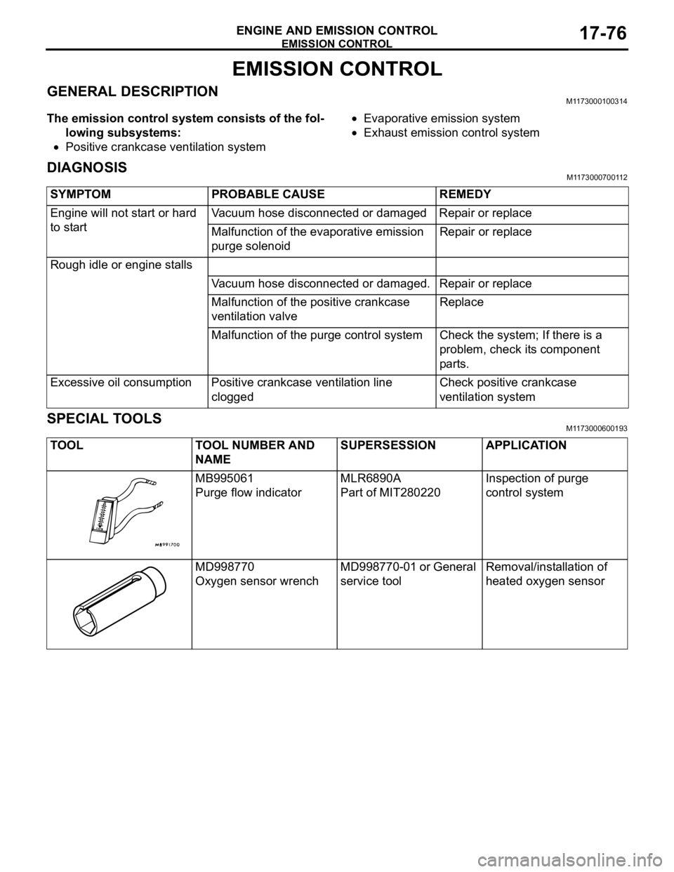
TOOL TOOL NUMBER AND
NAMESUPERSESSION APPLICATION
MB995061
Purge flow indicatorMLR6890A
Part of MIT280220Inspection of purge
control system
MD998770
Oxygen sensor wrenchMD998770-01 or General
service toolRemoval/installation of
heated oxygen sensor
Page 1415 of 1500
![MITSUBISHI 380 2005 Workshop Manual EMISSION CONTROL
ENGINE AND EMISSION CONTROL17-84
5. Measure the resistance between the terminals of the EVAP
purge solenoid.
Standard value: 16
[at 20C )]
6. Replace the solenoid if resistance is MITSUBISHI 380 2005 Workshop Manual EMISSION CONTROL
ENGINE AND EMISSION CONTROL17-84
5. Measure the resistance between the terminals of the EVAP
purge solenoid.
Standard value: 16
[at 20C )]
6. Replace the solenoid if resistance is](/img/19/57086/w960_57086-1414.png)
EMISSION CONTROL
ENGINE AND EMISSION CONTROL17-84
5. Measure the resistance between the terminals of the EVAP
purge solenoid.
Standard value: 16
[at 20C )]
6. Replace the solenoid if resistance is out of specification.
MASS AIRFLOW SENSOR CHECKM1173050400053
To inspect these parts, refer to GROUP 13A, Multipoint Fuel
Injection (MPI)
Multipoint Fuel Injection (MPI) Diagnosis
Diagnostic Trouble Code Chart 13A-17.
ENGINE COOLANT TEMPERATURE SENSOR
CHECK
M1173008100523
To inspect the sensor, refer to GROUP 13A, Multipoint Fuel
Injection (MPI)
Multipoint Fuel Injection (MPI) Diagnosis
Diagnostic Trouble Code Chart 13A-17.
INTAKE AIR TEMPERATURE SENSOR CHECKM1173008200263
To inspect the sensor, refer to GROUP 13A, Multipoint Fuel
Injection (MPI)
Multipoint Fuel Injection (MPI) Diagnosis
Diagnostic Trouble Code Chart 13A-17.
CATALYTIC CONVERTER
GENERAL DESCRIPTION (CATALYTIC CONVERTER)M1173005300131
The three way catalytic converter, together with the
closed loop air-fuel ratio control based on the oxygen
sensor signal, oxidizes carbon monoxides (CO) and
hydrocarbons (HC), also reduces nitrogen oxides
(NOx). When the mixture is controlled at stoichiometric
air-fuel ratio, the three way catalytic converter pro-
vides the highest purification against the three con-
stituents, namely, CO, HC and NOx.
Page 1426 of 1500
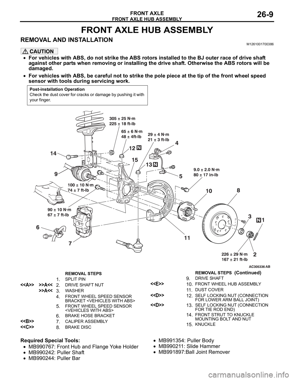
FRONT AXLE HUB ASSEMBLY
FRONT AXLE26-9
FRONT AXLE HUB ASSEMBLY
REMOVAL AND INSTALLATIONM1261001700386
For vehicles with ABS, do not strike the ABS rotors installed to the BJ outer race of drive shaft
against other parts when removing or installing the drive shaft. Otherwise the ABS rotors will be
damaged.
For vehicles with ABS, be careful not to strike the pole piece at the tip of the front wheel speed
sensor with tools during servicing work.
Required Special Tools:
MB990767: Front Hub and Flange Yoke Holder
MB990242: Puller Shaft
MB990244: Puller Bar
MB991354: Puller Body
MB990211: Slide Hammer
MB991897:Ball Joint Remover
Post-installation Operation
Check the dust cover for cracks or damage by pushing it with
your finger.
REMOVAL STEPS
1. SPLIT PIN
<> >>A<<2. DRIVE SHAFT NUT
>>A<<3. WASHER
4. FRONT WHEEL SPEED SENSOR
BRACKET
5. FRONT WHEEL SPEED SENSOR
6. BRAKE HOSE BRACKET
<> 7. CALIPER ASSEMBLY
<
9. DRIVE SHAFT
<
11 .DUST COVER
<
FOR LOWER ARM BALL JOINT)
<
FOR TIE ROD END)
14.FRONT STRUT TO KNUCKLE
MOUNTING BOLT AND NUT
15.KNUCKLE
REMOVAL STEPS (Continued)
Page 1430 of 1500
DRIVE SHAFT ASSEMBLY
FRONT AXLE26-13
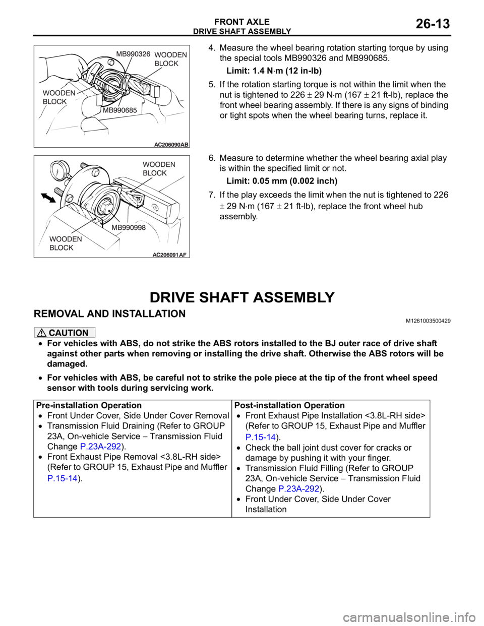
4. Measure the wheel bearing rotation starting torque by using
the special tools MB990326 and MB990685.
Limit: 1.4 N
m (12 in-lb)
5. If the rotation starting torque is not within the limit when the
nut is tightened to 226
29 Nm (167 21 ft-lb), replace the
front wheel bearing assembly. If there is any signs of binding
or tight spots when the wheel bearing turns, replace it.
6. Measure to determine whether the wheel bearing axial play
is within the specified limit or not.
Limit: 0.05 mm (0.002 inch)
7. If the play exceeds the limit when the nut is tightened to 226
29 Nm (167 21 ft-lb), replace the front wheel hub
assembly.
DRIVE SHAFT ASSEMBLY
REMOVAL AND INSTALLATIONM1261003500429
For vehicles with ABS, do not strike the ABS rotors installed to the BJ outer race of drive shaft
against other parts when removing or installing the drive shaft. Otherwise the ABS rotors will be
damaged.
For vehicles with ABS, be careful not to strike the pole piece at the tip of the front wheel speed
sensor with tools during servicing work.
Pre-installation Operation
Front Under Cover, Side Under Cover Removal
Transmission Fluid Draining (Refer to GROUP
23A, On-vehicle Service
Transmission Fluid
Change P.23A-292).
Front Exhaust Pipe Removal <3.8L-RH side>
(Refer to GROUP 15, Exhaust Pipe and Muffler
P.15-14).Post-installation Operation
Front Exhaust Pipe Installation <3.8L-RH side>
(Refer to GROUP 15, Exhaust Pipe and Muffler
P.15-14).
Check the ball joint dust cover for cracks or
damage by pushing it with your finger.
Transmission Fluid Filling (Refer to GROUP
23A, On-vehicle Service
Transmission Fluid
Change P.23A-292).
Front Under Cover, Side Under Cover
Installation
Page 1431 of 1500

DRIVE SHAFT ASSEMBLY
FRONT AXLE26-14
Required Special Tools:
MB990767: Front Hub and Flange Yoke Holder
MB991897: Ball Joint Remover
MB990242: Puller Shaft Puller
MB990244: Puller Bar
MB991354: Puller Body
MB990998: Front Hub Remover and Installer
MB991000: Spacer
REMOVAL STEPS
1. SPLIT PIN
<> >>B<<2. DRIVE SHAFT NUT
3. WASHER
4. FRONT WHEEL SPEED SENSOR
BRACKET
5. FRONT WHEEL SPEED SENSOR
6. BRAKE HOSE BRACKET
<>7. SELF LOCKING NUT (LOWER
ARM BALL JOINT CONNECTION)
<>8. SELF LOCKING NUT (TIE ROD
END CONNECTION)
<
<
SHAFT ASSEMBLY RH
11. CIRCLIPREMOVAL STEPS (Continued)
Page 1453 of 1500
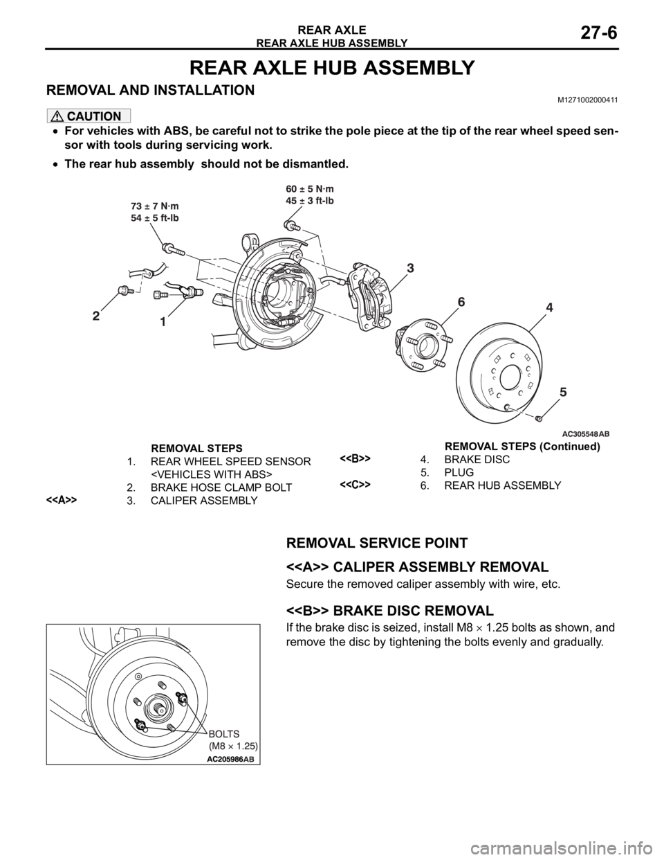
REAR AXLE HUB ASSEMBLY
REAR AXLE27-6
REAR AXLE HUB ASSEMBLY
REMOVAL AND INSTALLATIONM1271002000411
For vehicles with ABS, be careful not to strike the pole piece at the tip of the rear wheel speed sen-
sor with tools during servicing work.
The rear hub assembly should not be dismantled.
REMOVAL SERVICE POINT
.
<> CALIPER ASSEMBLY REMOVAL
Secure the removed caliper assembly with wire, etc.
.
<> BRAKE DISC REMOVAL
If the brake disc is seized, install M8 1.25 bolts as shown, and
remove the disc by tightening the bolts evenly and gradually.
.
REMOVAL STEPS
1. REAR WHEEL SPEED SENSOR
2. BRAKE HOSE CLAMP BOLT
<>3. CALIPER ASSEMBLY
<>4. BRAKE DISC
5. PLUG
<