fuse box MITSUBISHI 380 2005 Workshop Manual
[x] Cancel search | Manufacturer: MITSUBISHI, Model Year: 2005, Model line: 380, Model: MITSUBISHI 380 2005Pages: 1500, PDF Size: 47.87 MB
Page 10 of 1500

SWS DIAGNOSIS
SIMPLIFIED WIRING SYSTEM (SWS)54B-10
SWS DIAGNOSIS
GENERAL DESCRIPTION
BEFORE CARRYING OUT TROUBLESHOOTINGM1549014700710
Before carrying out troubleshooting, check the fol-
lowing two items.
Make sure that the ETACS-ECU, the junction
block (J/B), the front-ECU and the engine com-
partment relay box are connected securely.
Make sure that fuses and fusible links related to
relevant systems are not blown.
Refer to circuit diagrams GROUP-90
Refer to configuration diagrams GROUP-80
DIAGNOSTIC FUNCTIONM1549028900245
ON-BOARD DIAGNOSTICS
If an error occurs in the ECU or the SWS or CAN
communication line which performs the SWS or CAN
communication, the DTC is memorized in
ETACS-ECU. The DTCs have 11 items. The DTCs
are checked to connect diagnostic tool MB991958
(MUT-III sub assembly). The memorised DTCs are
not erased even if the ignition switch is turned to the
LOCK (OFF) position. The DTCs are erased to oper-
ate diagnostic tool MB991958 (MUT-III sub assem-
bly).NOTE:
*1: For vehicles that do not have a sunroof,
the diagnosis code is always sent but it does not indi-
cate a problem.
NOTE:
*2: The diagnosis code for the current prob-
lem is not sent.
NOTE:
*3: For vehicles that do not have a multi cen-
ter display (middle grade type), the diagnosis code is
always sent but it does not indicate a problem.
HOW TO CONNECT THE DIAGNOSTIC TOOL
(MUT-III)
Required Special Tools:
MB991958: DIAGNOSTIC TOOL (MUT-III Sub Assembly)
MB991824: Vehicle Communication Interface (V.C.I.)
MB991827: MUT-III USB Cable
MB991910: MUT-III Main Harness A DTC CODE TROUBLE CONTENT
001 or U1700 Malfunction of SWS communication line or ETACS-ECU
002 or U1701 Malfunction of column switch
003 or U1702 Malfunction of front-ECU
004
*1 or U1073Malfunction of sunroof-ECU
010
*2 or U1073Bus Off
011 or U1100 Engine ECU time-out
012 or U1101 A/T ECU time-out
013 or U1110 A/C-ECU time-out
014 or U1108 Combination meter time-out
015
*3 or U1111Multi center display unit time-out
021 or U1128 Failure information on combination meter
Page 590 of 1500

CENTRALISED JUNCTION
CIRCUIT DIAGRAMS90-13
19 Front-ECU (Field
effect transistor for
headlamp: Low)Fuse 10 Red Headlamp (LH) and headlamp (Low:
LH)
20 Front-ECU (Taillamp
relay)7.5 Brown A/C-ECU, A/T selector lever position
illumination lamp, combination meter,
fog lamp switch, headlamp (RH),
glove box lamp, hazard warning lamp
switch, multi-center display unit,
radio, CD player, rear combination
lamp (RH), rheostat and TCL switch
21 7.5 Brown Headlamp (LH), license plate lamp
and rear combination lamp (LH)
22 Battery/Alternator
(Fusible link No.27)15 Blue A/C-ECU, column switch,
combination meter, ETACS-ECU,
front-ECU, key reminder switch, multi-
center display unit, radio, CD player,
and vanity mirror lamp
23 Ignition switch (ACC) 10 Red A/C-ECU, accessory socket relay,
ETACS-ECU, multi-center display
unit, radio, CD player.
24 Battery/Alternator
(Fusible link No.27)15 Blue Fuel pump module
25 Ignition switch (ACC) 30 Green Front-ECU and windshield wiper
motor
26 Battery/Alternator
(Fusible link No.27)Fusible
link20 Light blue Anti-lock braking system(solenoid
valve)
27
Alternator120
Battery, front-ECU, fusible link Nos.1,
2, 3, 4, 5 and 26 and fuse Nos.6, 7, 8,
9, 10, 11, 13, 14, 15, 22 and 24 (in
relay box) NO. POWER SUPPLY
CIRCUITNAME RATED
CAPACITY (A)HOUSING
COLOURLOAD CIRCUIT
Page 1372 of 1500

AUTO-CRUISE CONTROL
ENGINE AND EMISSION CONTROL17-41
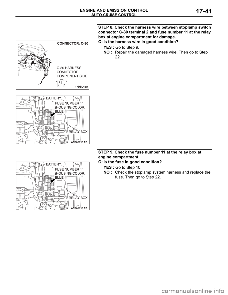
STEP 8. Check the harness wire between stoplamp switch
connector C-30 terminal 2 and fuse number 11 at the relay
box at engine compartment for damage.
Q: Is the harness wire in good condition?
YES : Go to Step 9.
NO : Repair the damaged harness wire. Then go to Step
22.
STEP 9. Check the fuse number 11 at the relay box at
engine compartment.
Q: Is the fuse in good condition?
YES : Go to Step 10.
NO : Check the stoplamp system harness and replace the
fuse. Then go to Step 22.