service MITSUBISHI 380 2005 Workshop Manual
[x] Cancel search | Manufacturer: MITSUBISHI, Model Year: 2005, Model line: 380, Model: MITSUBISHI 380 2005Pages: 1500, PDF Size: 47.87 MB
Page 1151 of 1500
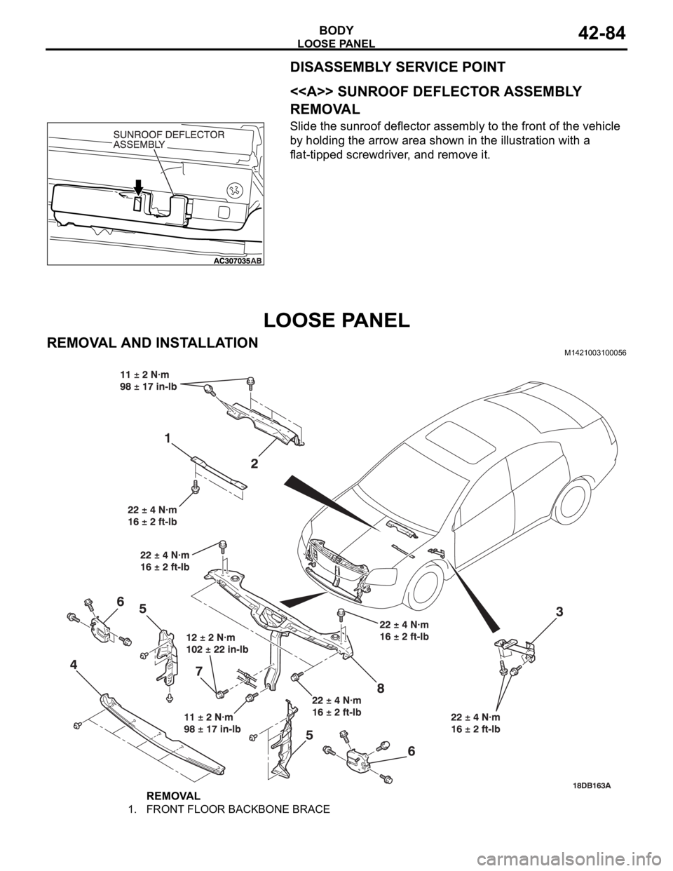
LOOSE PANEL
BODY42-84
DISASSEMBLY SERVICE POINT
.
<> SUNROOF DEFLECTOR ASSEMBLY
REMOVAL
Slide the sunroof deflector assembly to the front of the vehicle
by holding the arrow area shown in the illustration with a
flat-tipped screwdriver, and remove it.
LOOSE PANEL
REMOVAL AND INSTALLATIONM1421003100056
REMOVAL
1. FRONT FLOOR BACKBONE BRACE
Page 1154 of 1500

SPECIFICATIONS
BODY42-87
SERVICE SPECIFICATIONSM1421000300299
SEALANT AND ADHESIVESM1421000500204
Door inside handle knob play mm
(in)Front 26.1 - 58.1 (1.028 - 2.287) [Target
value 41 (1.61)]
Rear 30.3 - 58.1 (1.193 - 2.287) [Target
value 41 (1.61)]
Door inside handle lock knob stroke mm (in) 21.6 (0.850)
Door outside handle play mm (in) Front 10
3.5 (0.39 0.138)
Rear 11.2
4 (0.441 0.16)
Power window operation current A 5
1 [Power supply voltage 14.5
0.5V 25
C (77F)]
ITEM STANDARD VALUE
Roof lid glass operation current A 7 or less [at 20
C(68F)]
ITEM SPECIFIED ADHESIVE
Rear window glass 3 M
AAD part No. 8609 super fast urethane and 3 M AAD part No.
8608 super fast urethane primer or equivalent
Windshield
ITEM SPECIFIED SEALANT REMARK
Waterproof film 3 M
AAD Part No. 8633 or equivalent Ribbon sealer
ITEM SPECIFIED ADHESIVE TAPE
Front door opening outer
weatherstripAdhesive tape: Double-sided tape [7 mm (0.28 in) width, 85 mm (3.35
in) length and 0.8 mm (0.03 in) thickness]
Rear door opening outer
weatherstripAdhesive tape: Double-sided tape [7 mm (0.28 in) width, 50 mm (1.97
in) length and 0.8 mm (0.031 in) thickness]
ITEM SPECIFIED SEALANT REMARK
Trunk lid hinge 3 M
AAD part No. 8531 Heavy drip check sealer,
3 M
AAD part No. 8646 Automotive joint and
seam sealer or equivalentBody sealer
Page 1156 of 1500

21A-1
GROUP 21A
CLUTCH
CONTENTS
GENERAL INFORMATION . . . . . . . .21A-2
SERVICE SPECIFICATIONS . . . . . . .21A-2
LUBRICANTS . . . . . . . . . . . . . . . . . .21A-2
ON-VEHICLE SERVICE . . . . . . . . . . .21A-2
CLUTCH PEDAL CHECK AND
ADJUSTMENT . . . . . . . . . . . . . . . . . . . . . . 21A-2
CLUTCH BLEEDING . . . . . . . . . . . . . . . . . 21A-3
CLUTCH PEDAL. . . . . . . . . . . . . . . . .21A-4
REMOVAL AND INSTALLATION . . . . . . . . 21A-4
CLUTCH CONTROL . . . . . . . . . . . . . .21A-5
REMOVAL AND INSTALLATION . . . . . . . . 21A-5
INSPECTION. . . . . . . . . . . . . . . . . . . . . . . . 21A-6
DISASSEMBLY AND REASSEMBLY . . . . . 21A-7
INSPECTION. . . . . . . . . . . . . . . . . . . . . . . . 21A-8
Page 1157 of 1500
GENERAL INFORMATION
CLUTCH21A-2
GENERAL INFORMATION
M1211000100234
The clutch is a dry single-disc, diaphragm type;
hydraulic pressure is used for the clutch control. The
clutch shares a brake fluid reservoir with the brake
system.
SERVICE SPECIFICATIONS
M1211000300227
LUBRICANTS
M1211000400183
ON-VEHICLE SERVICE
CLUTCH PEDAL CHECK AND
ADJUSTMENT
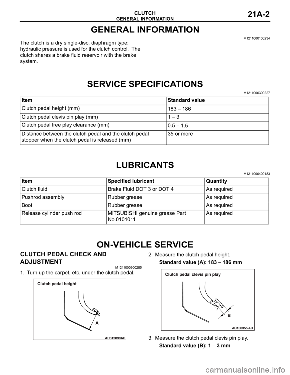
M1211000900285
1. Turn up the carpet, etc. under the clutch pedal.2. Measure the clutch pedal height.
Standard value (A): 183
186 mm
3. Measure the clutch pedal clevis pin play.
Standard value (B): 1
3 mm Item Standard value
Clutch pedal height (mm)
183
186
Clutch pedal clevis pin play (mm) 1
3
Clutch pedal free play clearance (mm)
0.5
1.5
Distance between the clutch pedal and the clutch pedal
stopper when the clutch pedal is released (mm)35 or more
Item Specified lubricant Quantity
Clutch fluid Brake Fluid DOT 3 or DOT 4 As required
Pushrod assembly Rubber grease As required
Boot Rubber grease As required
Release cylinder push rod MITSUBISHI genuine grease Part
No.0101011As required
Page 1158 of 1500
ON-VEHICLE SERVICE
CLUTCH21A-3
Do not push in the master cylinder pushrod at
this time, otherwise the clutch will not operate
properly.
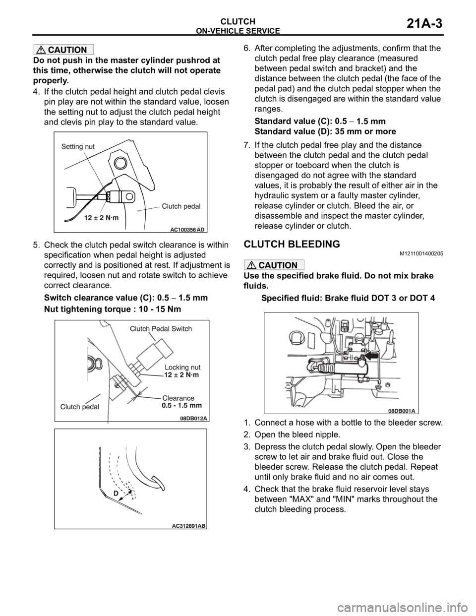
4. If the clutch pedal height and clutch pedal clevis
pin play are not within the standard value, loosen
the setting nut to adjust the clutch pedal height
and clevis pin play to the standard value.
5. Check the clutch pedal switch clearance is within
specification when pedal height is adjusted
correctly and is positioned at rest. If adjustment is
required, loosen nut and rotate switch to achieve
correct clearance.
Switch clearance value (C): 0.5
1.5 mm
Nut tightening torque : 10 - 15 Nm6. After completing the adjustments, confirm that the
clutch pedal free play clearance (measured
between pedal switch and bracket) and the
distance between the clutch pedal (the face of the
pedal pad) and the clutch pedal stopper when the
clutch is disengaged are within the standard value
ranges.
Standard value (C): 0.5
1.5 mm
Standard value (D): 35 mm or more
7. If the clutch pedal free play and the distance
between the clutch pedal and the clutch pedal
stopper or toeboard when the clutch is
disengaged do not agree with the standard
values, it is probably the result of either air in the
hydraulic system or a faulty master cylinder,
release cylinder or clutch. Bleed the air, or
disassemble and inspect the master cylinder,
release cylinder or clutch.
CLUTCH BLEEDINGM1211001400205
Use the specified brake fluid. Do not mix brake
fluids.
Specified fluid: Brake fluid DOT 3 or DOT 4
1. Connect a hose with a bottle to the bleeder screw.
2. Open the bleed nipple.
3. Depress the clutch pedal slowly. Open the bleeder
screw to let air and brake fluid out. Close the
bleeder screw. Release the clutch pedal. Repeat
until only brake fluid and no air comes out.
4. Check that the brake fluid reservoir level stays
between "MAX" and "MIN" marks throughout the
clutch bleeding process.
Page 1161 of 1500
Page 1163 of 1500
CLUTCH CONTROL
CLUTCH21A-8
REASSEMBLY SERVICE POINT
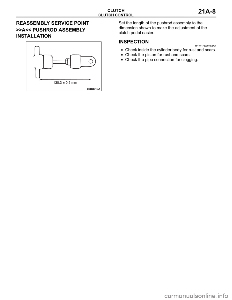
>>A<< PUSHROD ASSEMBLY
INSTALLATIONSet the length of the pushrod assembly to the
dimension shown to make the adjustment of the
clutch pedal easier.
INSPECTIONM1211002200152
Check inside the cylinder body for rust and scars.
Check the piston for rust and scars.
Check the pipe connection for clogging.
Page 1164 of 1500

35-1
GROUP 35
SERVICE BRAKES
CONTENTS
BASIC BRAKE SYSTEM . . . . . . . . . . . . . . . . . . . . . . . . . . . . . .35A
ANTI-LOCK BRAKING SYSTEM (ABS). . . . . . . . . . . . . . . . . . .35B
Page 1166 of 1500
35A-1
GROUP 35A
BASIC BRAKE
SYSTEM
CONTENTS
GENERAL DESCRIPTION. . . . . . . . .35A-2
BASIC BRAKE SYSTEM DIAGNOSIS35A-3
INTRODUCTION TO BASIC BRAKE
SYSTEM DIAGNOSIS . . . . . . . . . . . . . . . . 35A-3
BASIC BRAKE SYSTEM DIAGNOSTIC
TROUBLESHOOTING STRATEGY . . . . . . 35A-3
SYMPTOM CHART. . . . . . . . . . . . . . . . . . . 35A-3
SYMPTOM PROCEDURES . . . . . . . . . . . . 35A-3
SPECIAL TOOLS . . . . . . . . . . . . . . . .35A-12
ON-VEHICLE SERVICE . . . . . . . . . . .35A-13
BRAKE PEDAL CHECK AND
ADJUSTMENT . . . . . . . . . . . . . . . . . . . . . . 35A-13
BRAKE BOOSTER OPERATING TEST . . . 35A-14
CHECK VALVE OPERATION CHECK . . . . 35A-15
BLEEDING . . . . . . . . . . . . . . . . . . . . . . . . . 35A-16
BRAKE FLUID LEVEL SENSOR CHECK. . 35A-17
DISC BRAKE PAD CHECK AND
REPLACEMENT . . . . . . . . . . . . . . . . . . . . . 35A-17
DISC BRAKE ROTOR CHECK . . . . . . . . . . 35A-19
MASTER CYLINDER FUNCTION CHECK . 35A-23
BRAKE PEDAL. . . . . . . . . . . . . . . . . .35A-24
REMOVAL AND INSTALLATION . . . . . . . . 35A-24
INSPECTION. . . . . . . . . . . . . . . . . . . . . . . . 35A-25
MASTER CYLINDER ASSEMBLY
AND BRAKE BOOSTER . . . . . . . . . .35A-26
REMOVAL AND INSTALLATION . . . . . . . . 35A-26
MASTER CYLINDER . . . . . . . . . . . . . . . . . 35A-28
INSPECTION. . . . . . . . . . . . . . . . . . . . . . . . 35A-29
DISC BRAKE ASSEMBLY . . . . . . . . .35A-30
REMOVAL AND INSTALLATION . . . . . . . . 35A-30
INSPECTION. . . . . . . . . . . . . . . . . . . . . . . . 35A-32
DISASSEMBLY AND ASSEMBLY
DISASSEMBLY AND ASSEMBLY
INSPECTION. . . . . . . . . . . . . . . . . . . . . . . . 35A-38
SPECIFICATIONS . . . . . . . . . . . . . . .35A-40
FASTENER TIGHTENING
SPECIFICATIONS. . . . . . . . . . . . . . . . . . . . 35A-40
GENERAL SPECIFICATIONS . . . . . . . . . . 35A-40
SERVICE SPECIFICATIONS . . . . . . . . . . . 35A-41
LUBRICANTS . . . . . . . . . . . . . . . . . . . . . . . 35A-41
Page 1167 of 1500
GENERAL DESCRIPTION
BASIC BRAKE SYSTEM35A-2
GENERAL DESCRIPTIONM1351000100440
The brake system has been designed to give greater
reliability and durability and to provide excellent brak-
ing performance.
FEATURES
.
Improved braking performance
1. An 8+9 inch tandem brake booster provides suffi-
cient braking force in sudden braking range.
2. 296mm front ventilated disc brakes provide sta-
ble braking force and improved braking feel.
3. 303mm rear ventillated disc brakes are used.
.
Improved stability
1. A 4-wheel anti-lock braking system (4ABS) pre-
vents slipping caused by the vehicle wheels lock-
ing up, in order to maintain a stable vehicle
posture and steering performance.
2. An electronic brake-force distribution (EBD)
makes it possible to maintain the maximum
amount of braking force even when the vehicle's
load is unevenly distributed. 3. Front- and rear-wheel X-type brake line layout
are used.
4. Ventilated discs brakes improve anti-fading per-
formance.
.
Improved serviceability
1. A diagnosis function for the ABS system makes
inspection easier.
2. An outer disc separated hub and rotor make
removal and installation easier.
3. The master cylinder reservoir is utilised for both
brake and clutch fluid on manual transmission
vehicles.
4. The master cylinder filter is coloured black for
improved viewing.
5. The ABS-ECU and hydraulic unit are integrated
to make them more compact and light weight.
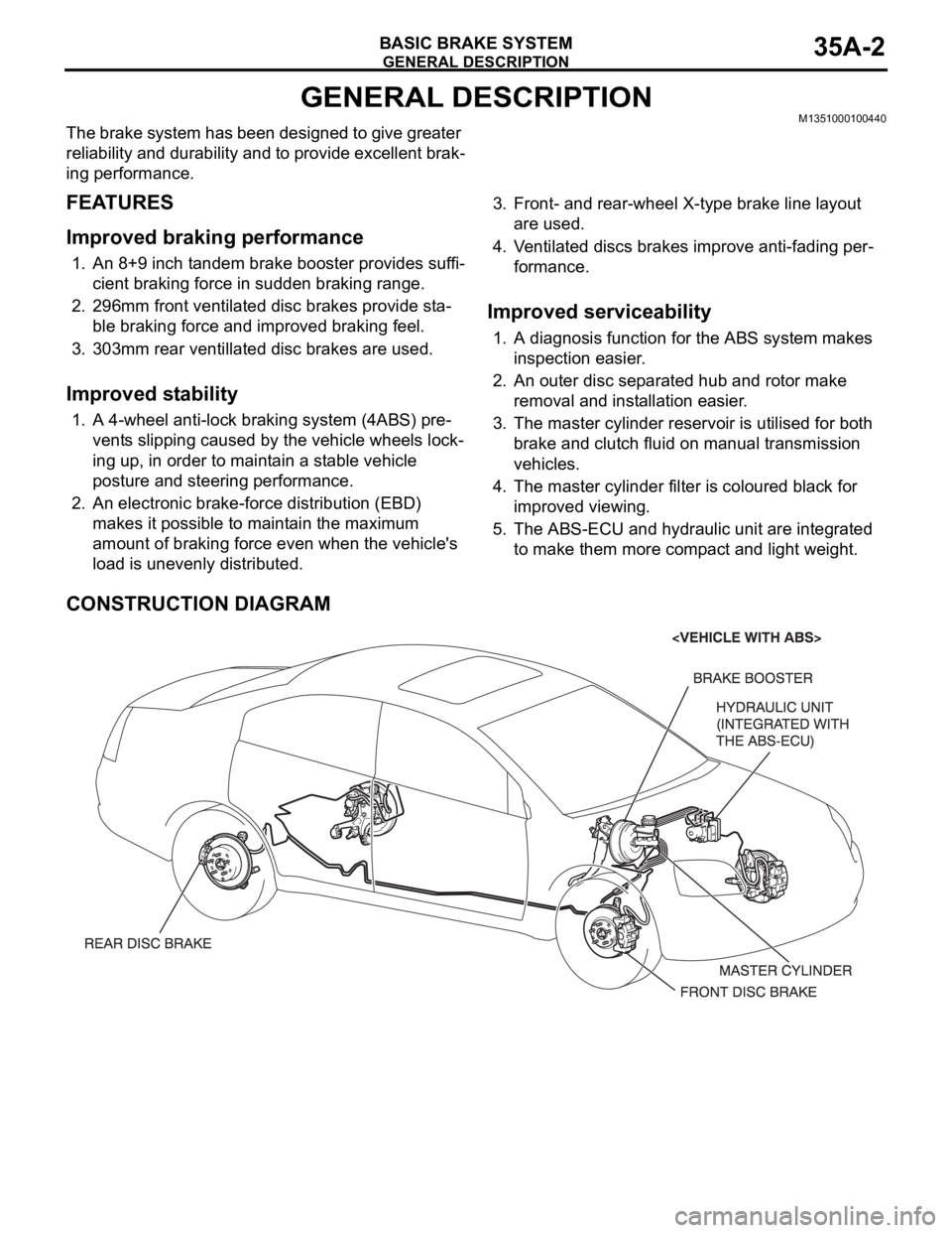
CONSTRUCTION DIAGRAM