service MITSUBISHI 380 2005 Workshop Manual
[x] Cancel search | Manufacturer: MITSUBISHI, Model Year: 2005, Model line: 380, Model: MITSUBISHI 380 2005Pages: 1500, PDF Size: 47.87 MB
Page 1020 of 1500
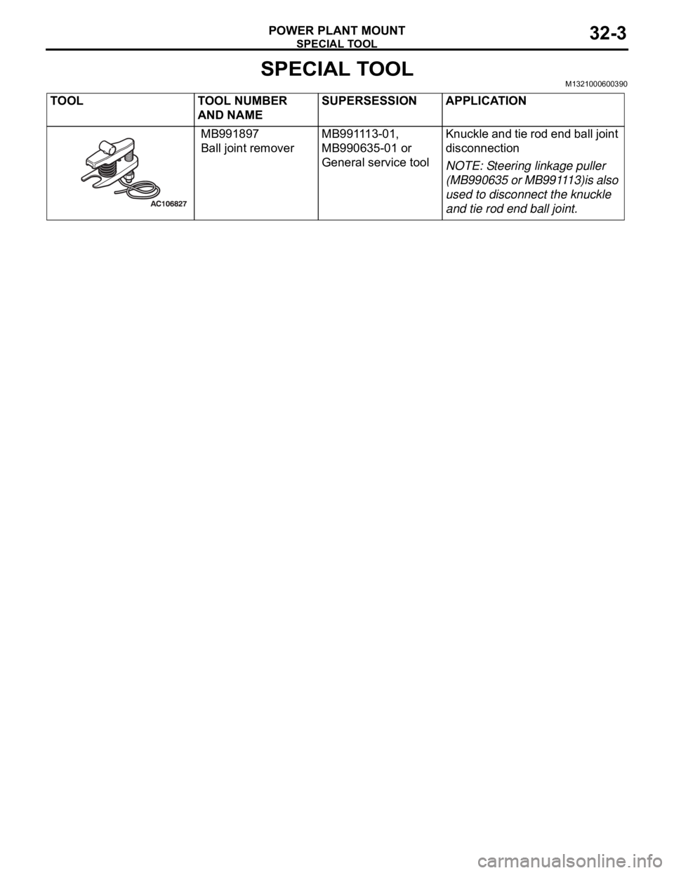
SPECIAL TOOL
POWER PLANT MOUNT32-3
SPECIAL TOOLM1321000600390
TOOL TOOL NUMBER
AND NAMESUPERSESSION APPLICATION
MB991897
Ball joint removerMB991113-01,
MB990635-01 or
General service tool Knuckle and tie rod end ball joint
disconnection
NOTE: Steering linkage puller
(MB990635 or MB991113)is also
used to disconnect the knuckle
and tie rod end ball joint.
Page 1023 of 1500
TRANSAXLE MOUNTING
POWER PLANT MOUNT32-6
INSTALLATION SERVICE POINT
.
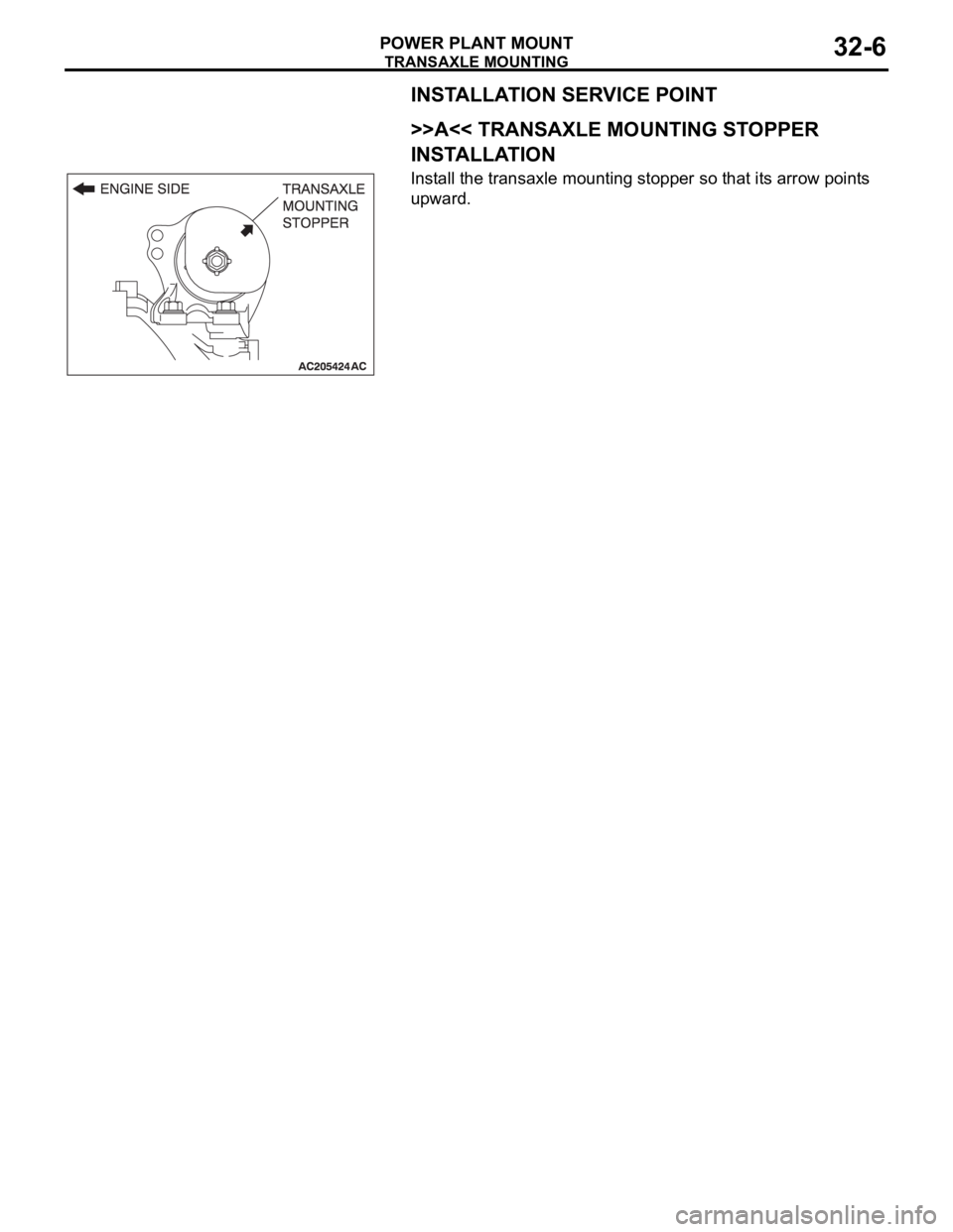
>>A<< TRANSAXLE MOUNTING STOPPER
INSTALLATION
Install the transaxle mounting stopper so that its arrow points
upward.
Page 1025 of 1500
ENGINE ROLL STOPPER AND CENTREMEMBER
POWER PLANT MOUNT32-8
INSTALLATION SERVICE POINTS
.
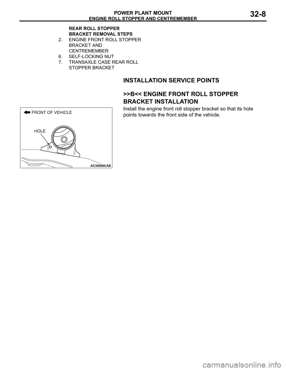
>>B<< ENGINE FRONT ROLL STOPPER
BRACKET INSTALLATION
Install the engine front roll stopper bracket so that its hole
points towards the front side of the vehicle.
2. ENGINE FRONT ROLL STOPPER
BRACKET AND
CENTREMEMBER
6. SELF-LOCKING NUT
7. TRANSAXLE CASE REAR ROLL
STOPPER BRACKET REAR ROLL STOPPER
BRACKET REMOVAL STEPS
Page 1026 of 1500
CROSSMEMBER
POWER PLANT MOUNT32-9
CROSSMEMBER
REMOVAL AND INSTALLATIONM1321003200551
Before removing the steering wheel and air bag module assembly, always refer to GROUP 52B -
Service Precautions (P.52B-16), Air bag Module and Clock Spring (P.52B-237). Also, set the front
wheels so that they are facing straight forward, and remove the ignition key. If you fail to do this,
the SRS clock spring will be damaged, causing the SRS air bag to be inoperative and serious
injury.
*1: Indicates parts which should be initially tightened, and then fully tightened after placing the
vehicle horizontally and loading the full weight of the engine on the vehicle body.
*2: Indicates parts which should be temporarily tightened, and then fully tightened with the vehicle
on the ground in the unladen condition.
Pre-removal Operation
Power Steering Fluid Draining (Refer to GROUP 37,
On-vehicle Service Fluid Replacement P.37-18).
Power Steering Hoses Removal and Installation (Refer to
GROUP 37, Power Steering Hoses P.37A-57).
Air Bag Module and Steering Wheel Assembly Removal
(Refer to GROUP 37, Steering Wheel P.37-23).
Clock Spring Removal (Refer to GROUP 52B, Air Bag
Module and Clock Spring P.52B-237).
Floor Console Assembly Removal (Refer to GROUP 52A,
Floor Console Assembly P.52A-10).
Front Scuff Plate (LH) and Cowl Side Trim (LH) Removal
(Refer to GROUP 52A, Trims P.52A-11).
Trunk Lid Release Handle Cover Removal (Refer to
GROUP 42, Trunk Lid P.42-63).
Accelerator Stopper Removal (Refer to GROUP 17,
Accelerator Pedal P.17-9).
Front Floor Carpet Removal
Centremember Removal (Refer to P.32-7).Post-installation Operation
Centremember Installation (Refer to P.32-7).
Front Floor Carpet Installation
Accelerator Stopper Installation (Refer to GROUP 17,
Accelerator Pedal P.17-9).
Trunk Lid Release Handle Cover Installation (Refer to
GROUP 42, Trunk Lid P.42-63).
Front Scuff Plate (LH) and Cowl Side Trim (LH) Installa-
tion (Refer to GROUP 52A, Trims P.52A-11).
Floor Console Assembly Installation (Refer to GROUP
52A, Floor Console Assembly P.52A-10).
Clock Spring Installation (Refer to GROUP 52B, Air Bag
Module and Clock Spring P.52B-237).
Steering Wheel Assembly and Air Bag Module Installation
(Refer to P.37-23).
Check the dust cover for cracks or damage by pushing it
with your finger.
Power Steering Fluid Supplying (Refer to GROUP 37,
On-vehicle Service Fluid Replacement P.37-18).
Power Steering Fluid Line Bleeding (Refer to P.37-18).
Checking Steering Wheel Position with Wheels Straight
Ahead.
Front Wheel Alignment Adjustment (Refer to GROUP 33,
On-vehicle Service
Front Wheel Alignment Check and
Adjustment P.33-6).
Page 1028 of 1500
CROSSMEMBER
POWER PLANT MOUNT32-11
Required Special Tool:
MB991897: Ball Joint Remover
REMOVAL SERVICE POINTS
.
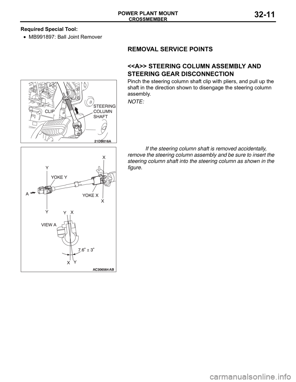
<> STEERING COLUMN ASSEMBLY AND
STEERING GEAR DISCONNECTION
Pinch the steering column shaft clip with pliers, and pull up the
shaft in the direction shown to disengage the steering column
assembly.
NOTE:
If the steering column shaft is removed accidentally,
remove the steering column assembly and be sure to insert the
steering column shaft into the steering column as shown in the
figure.
.
Page 1030 of 1500
CROSSMEMBER
POWER PLANT MOUNT32-13
<
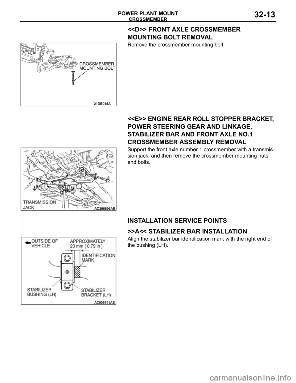
MOUNTING BOLT REMOVAL
Remove the crossmember mounting bolt.
.
<
POWER STEERING GEAR AND LINKAGE,
STABILIZER BAR AND FRONT AXLE NO.1
CROSSMEMBER ASSEMBLY REMOVAL
Support the front axle number 1 crossmember with a transmis-
sion jack, and then remove the crossmember mounting nuts
and bolts.
INSTALLATION SERVICE POINTS
.
>>A<< STABILIZER BAR INSTALLATION
Align the stabilizer bar identification mark with the right end of
the bushing (LH).
.
Page 1034 of 1500
51-1
GROUP 51
EXTERIOR
CONTENTS
FRONT BUMPER ASSEMBLY . . . . .51-2
REMOVAL AND INSTALLATION . . . . . . . . 51-2
DISASSEMBLY AND ASSEMBLY . . . . . . . 51-3
REAR BUMPER ASSEMBLY . . . . . .51-5
REMOVAL AND INSTALLATION . . . . . . . . 51-5
RADIATOR GRILLE. . . . . . . . . . . . . .51-6
REMOVAL AND INSTALLATION . . . . . . . . 51-6
GARNISHES AND MOLDINGS . . . . .51-7
SPECIAL TOOLS . . . . . . . . . . . . . . . . . . . . 51-7
MOLDINGS . . . . . . . . . . . . . . . . . . . . . . . . . 51-8
REMOVAL AND INSTALLATION . . . . . . . . 51-8
REAR SPOILER . . . . . . . . . . . . . . . . .51-11
REMOVAL AND INSTALLATION . . . . . . . . 51-11
MUD GUARD . . . . . . . . . . . . . . . . . . .51-12
REMOVAL AND INSTALLATION . . . . . . . . 51-12
UNDER COVER . . . . . . . . . . . . . . . . .51-13
REMOVAL AND INSTALLATION . . . . . . . . 51-13
WINDSHIELD WIPER AND WASHER51-14
GENERAL DESCRIPTION . . . . . . . . . . . . . 51-14
WINDSHIELD WIPER AND WASHER DIAGNOSIS . . . . . . . . . . . . . . . . . . . . . . . . . 51-14
SPECIAL TOOLS . . . . . . . . . . . . . . . . . . . . 51-15
ON-VEHICLE SERVICE . . . . . . . . . . . . . . . 51-15
WINDSHIELD INTERMITTENT WIPER
VOLUME CHECK . . . . . . . . . . . . . . . . . . . . 51-15
WINDSHIELD WASHER FLUID EJECTION
CHECK . . . . . . . . . . . . . . . . . . . . . . . . . . . . 51-16
WINDSHIELD WIPER . . . . . . . . . . . . . . . . . 51-17
REMOVAL AND INSTALLATION . . . . . . . . 51-17
INSPECTION. . . . . . . . . . . . . . . . . . . . . . . . 51-20
WINDSHIELD WASHER . . . . . . . . . . . . . . . 51-23
REMOVAL AND INSTALLATION . . . . . . . . 51-23
INSPECTION. . . . . . . . . . . . . . . . . . . . . . . . 51-24
MARK . . . . . . . . . . . . . . . . . . . . . . . . .51-25
REMOVAL AND INSTALLATION . . . . . . . . 51-25
DOOR MIRROR . . . . . . . . . . . . . . . . .51-27
GENERAL DESCRIPTION . . . . . . . . . . . . . 51-27
DOOR MIRROR . . . . . . . . . . . . . . . . . . . . . 51-28
REMOVAL AND INSTALLATION . . . . . . . . 51-28
INSPECTION. . . . . . . . . . . . . . . . . . . . . . . . 51-29
SPECIFICATIONS . . . . . . . . . . . . . . .51-31
FASTENER TIGHTENING SPECIFICATIONS51-31
SERVICE SPECIFICATIONS . . . . . . . . . . . 51-31
ADHESIVE . . . . . . . . . . . . . . . . . . . . . . . . . 51-31
Page 1036 of 1500
FRONT BUMPER ASSEMBLY
EXTERIOR51-3
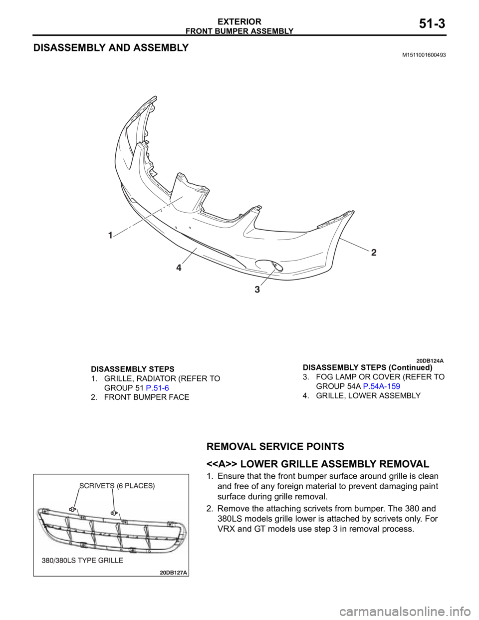
DISASSEMBLY AND ASSEMBLYM1511001600493
REMOVAL SERVICE POINTS
.
<> LOWER GRILLE ASSEMBLY REMOVAL
1. Ensure that the front bumper surface around grille is clean
and free of any foreign material to prevent damaging paint
surface during grille removal.
2. Remove the attaching scrivets from bumper. The 380 and
380LS models grille lower is attached by scrivets only. For
VRX and GT models use step 3 in removal process.
DISASSEMBLY STEPS
1. GRILLE, RADIATOR (REFER TO
GROUP 51 P.51-6
2. FRONT BUMPER FACE3. FOG LAMP OR COVER (REFER TO
GROUP 54A P.54A-159
4. GRILLE, LOWER ASSEMBLY DISASSEMBLY STEPS (Continued)
Page 1039 of 1500
RADIATOR GRILLE
EXTERIOR51-6
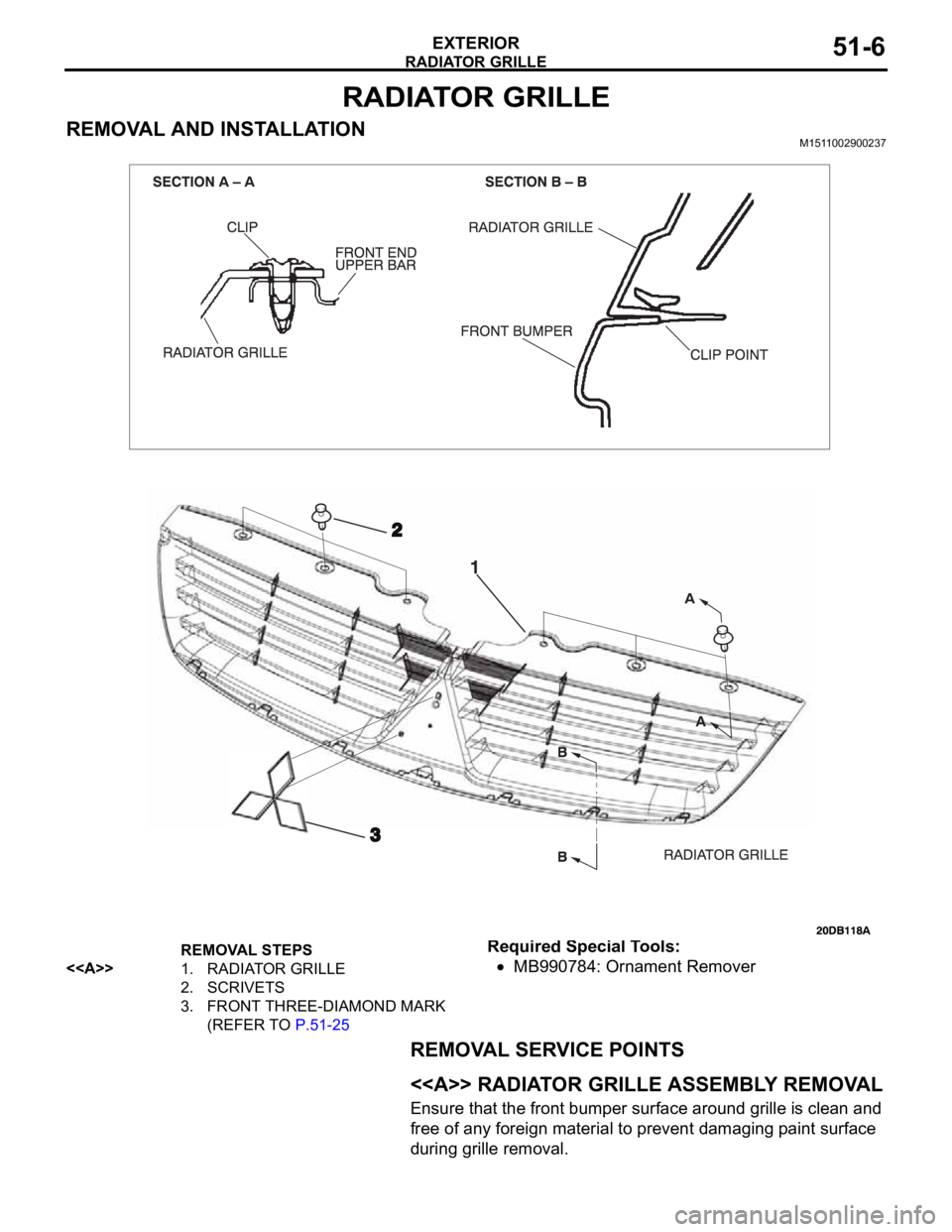
RADIATOR GRILLE
REMOVAL AND INSTALLATIONM1511002900237
Required Special Tools:
MB990784: Ornament Remover
REMOVAL SERVICE POINTS
.
<> RADIATOR GRILLE ASSEMBLY REMOVAL
Ensure that the front bumper surface around grille is clean and
free of any foreign material to prevent damaging paint surface
during grille removal.
REMOVAL STEPS
<>
1. RADIATOR GRILLE
2. SCRIVETS
3. FRONT THREE-DIAMOND MARK
(REFER TO P.51-25
Page 1040 of 1500
GARNISHES AND MOLDINGS
EXTERIOR51-7
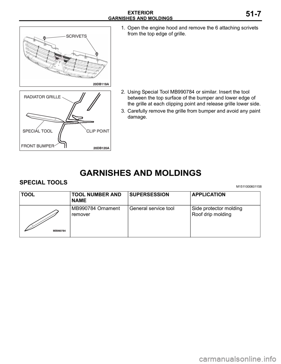
1. Open the engine hood and remove the 6 attaching scrivets
from the top edge of grille.
2. Using Special Tool MB990784 or similar. Insert the tool
between the top surface of the bumper and lower edge of
the grille at each clipping point and release grille lower side.
3. Carefully remove the grille from bumper and avoid any paint
damage.
GARNISHES AND MOLDINGS
SPECIAL TOOLSM1511000601158
TOOL TOOL NUMBER AND
NAMESUPERSESSION APPLICATION
MB990784 Ornament
removerGeneral service tool Side protector molding
Roof drip molding