service MITSUBISHI 380 2005 Workshop Manual
[x] Cancel search | Manufacturer: MITSUBISHI, Model Year: 2005, Model line: 380, Model: MITSUBISHI 380 2005Pages: 1500, PDF Size: 47.87 MB
Page 1042 of 1500
GARNISHES AND MOLDINGS
EXTERIOR51-9
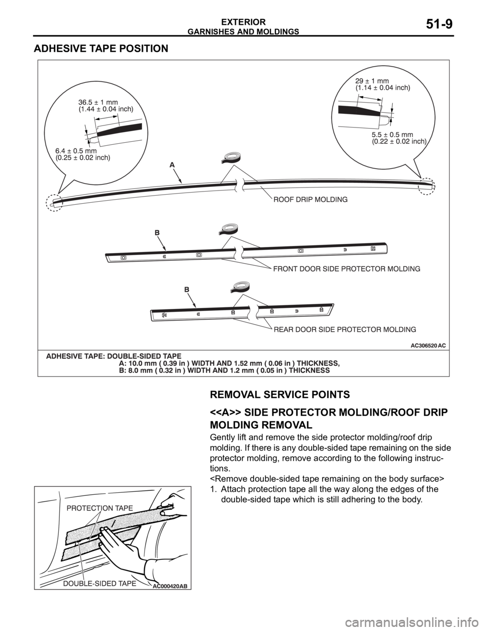
ADHESIVE TAPE POSITION
REMOVAL SERVICE POINTS
.
<> SIDE PROTECTOR MOLDING/ROOF DRIP
MOLDING REMOVAL
Gently lift and remove the side protector molding/roof drip
molding. If there is any double-sided tape remaining on the side
protector molding, remove according to the following instruc-
tions.
1. Attach protection tape all the way along the edges of the
double-sided tape which is still adhering to the body.
Page 1043 of 1500
GARNISHES AND MOLDINGS
EXTERIOR51-10
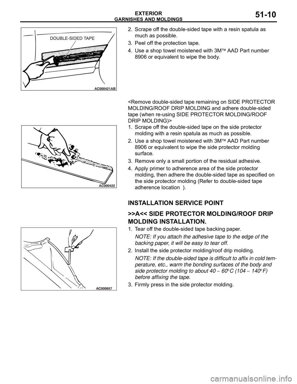
2. Scrape off the double-sided tape with a resin spatula as
much as possible.
3. Peel off the protection tape.
4. Use a shop towel moistened with 3M
AAD Part number
8906 or equivalent to wipe the body.
.
tape (when re-using SIDE PROTECTOR MOLDING/ROOF
DRIP MOLDING)>
1. Scrape off the double-sided tape on the side protector
molding with a resin spatula as much as possible.
2. Use a shop towel moistened with 3M
AAD Part number
8906 or equivalent to wipe the side protector molding
surface.
3. Remove only a small portion of the residual adhesive.
4. Apply primer to adherence area of the side protector
molding, then adhere the double-sided tape as specified on
the side protector molding (Refer to double-sided tape
adherence location ).
INSTALLATION SERVICE POINT
.
>>A<< SIDE PROTECTOR MOLDING/ROOF DRIP
MOLDING INSTALLATION.
1. Tear off the double-sided tape backing paper.
NOTE: If you attach the adhesive tape to the edge of the
backing paper, it will be easy to tear off.
2. Install the side protector molding/roof drip molding.
NOTE: If the double-sided tape is difficult to affix in cold tem-
perature, etc., warm the bonding surfaces of the body and
side protector molding to about 40
60C (104 140F)
before affixing the tape.
3. Firmly press in the side protector molding.
Page 1048 of 1500
WINDSHIELD WIPER AND WASHER
EXTERIOR51-15
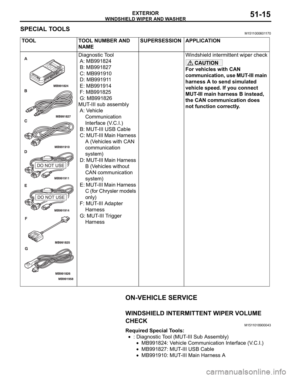
SPECIAL TOOLSM1511000601170
ON-VEHICLE SERVICE
WINDSHIELD INTERMITTENT WIPER VOLUME
CHECK
M1511018900043
Required Special Tools:
: Diagnostic Tool (MUT-III Sub Assembly)
MB991824: Vehicle Communication Interface (V.C.I.)
MB991827: MUT-III USB Cable
MB991910: MUT-III Main Harness A TOOL TOOL NUMBER AND
NAMESUPERSESSION APPLICATION
Diagnostic Tool
A: MB991824
B: MB991827
C: MB991910
D: MB991911
E: MB991914
F: MB991825
G: MB991826
MUT-III sub assembly
A: Vehicle
Communication
Interface (V.C.I.)
B: MUT-III USB Cable
C: MUT-III Main Harness
A (Vehicles with CAN
communication
system)
D: MUT-III Main Harness
B (Vehicles without
CAN communication
system)
E: MUT-III Main Harness
C (for Chrysler models
only)
F: MUT-III Adapter
Harness
G: MUT-III Trigger
HarnessWindshield intermittent wiper check
For vehicles with CAN
communication, use MUT-III main
harness A to send simulated
vehicle speed. If you connect
MUT-III main harness B instead,
the CAN communication does
not function correctly.
Page 1052 of 1500
WINDSHIELD WIPER AND WASHER
EXTERIOR51-19
INSTALLATION SERVICE POINTS
.
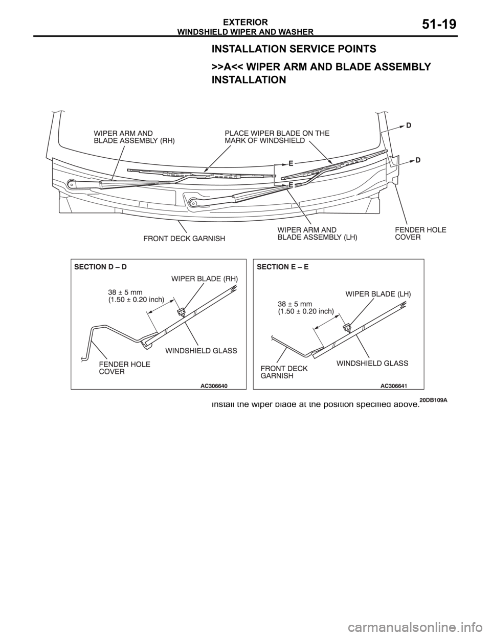
>>A<< WIPER ARM AND BLADE ASSEMBLY
INSTALLATION
Install the wiper blade at the position specified above.
.
Page 1059 of 1500
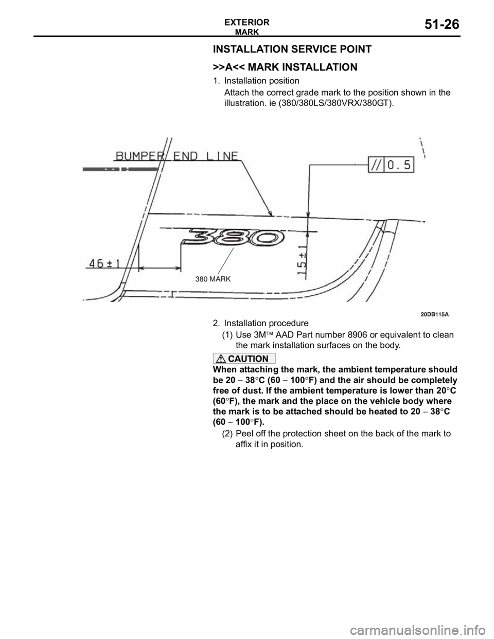
MARK
EXTERIOR51-26
INSTALLATION SERVICE POINT
.
>>A<< MARK INSTALLATION
1. Installation position
Attach the correct grade mark to the position shown in the
illustration. ie (380/380LS/380VRX/380GT).
2. Installation procedure
(1) Use 3M
AAD Part number 8906 or equivalent to clean
the mark installation surfaces on the body.
When attaching the mark, the ambient temperature should
be 20
38C (60 100F) and the air should be completely
free of dust. If the ambient temperature is lower than 20
C
(60
F), the mark and the place on the vehicle body where
the mark is to be attached should be heated to 20
38C
(60
100F).
(2) Peel off the protection sheet on the back of the mark to
affix it in position.
Page 1062 of 1500
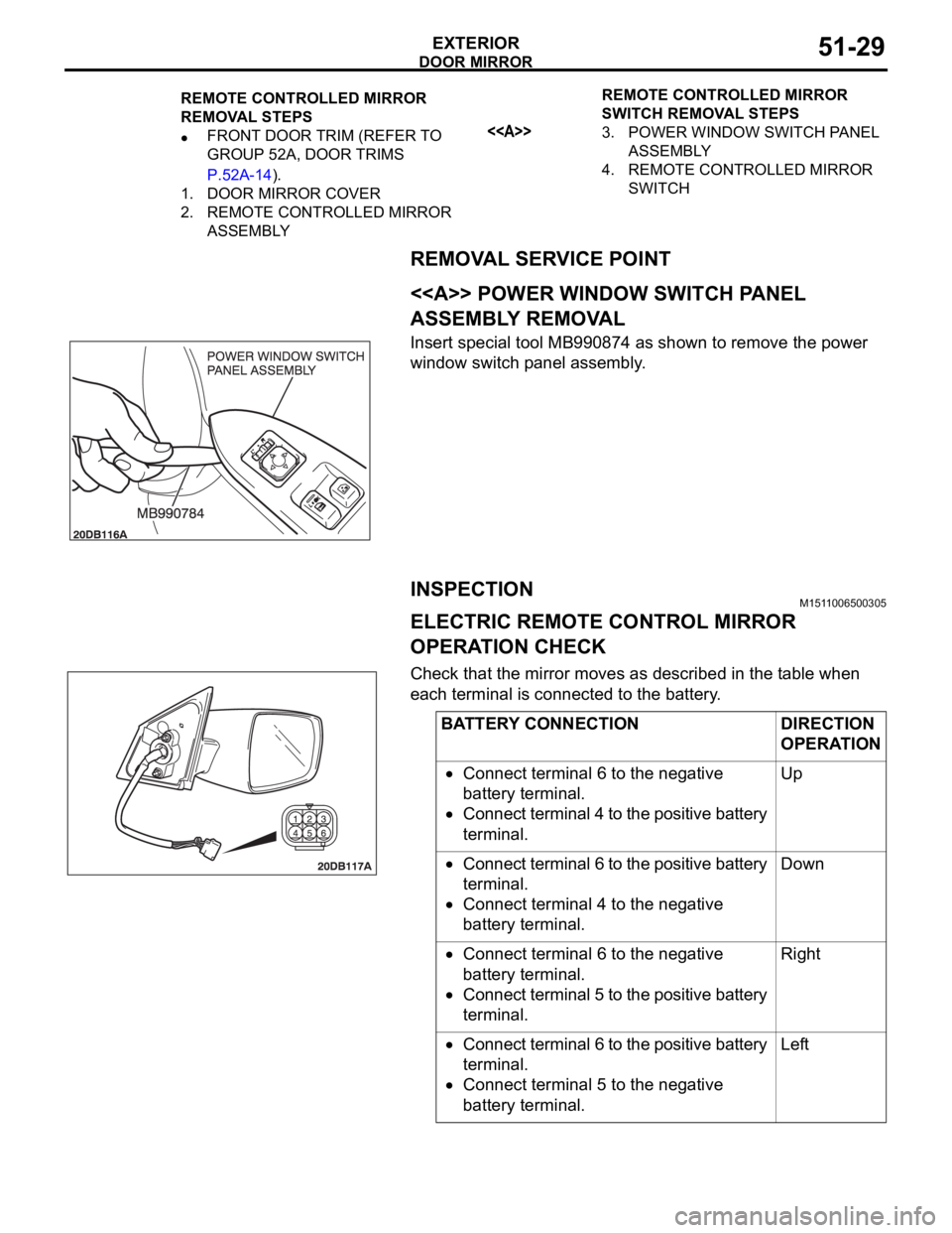
DOOR MIRROR
EXTERIOR51-29
REMOVAL SERVICE POINT
.
<> POWER WINDOW SWITCH PANEL
ASSEMBLY REMOVAL
Insert special tool MB990874 as shown to remove the power
window switch panel assembly.
INSPECTIONM1511006500305
ELECTRIC REMOTE CONTROL MIRROR
OPERATION CHECK
Check that the mirror moves as described in the table when
each terminal is connected to the battery.
REMOTE CONTROLLED MIRROR
REMOVAL STEPS
FRONT DOOR TRIM (REFER TO
GROUP 52A, DOOR TRIMS
P.52A-14).
1. DOOR MIRROR COVER
2. REMOTE CONTROLLED MIRROR
ASSEMBLYREMOTE CONTROLLED MIRROR
SWITCH REMOVAL STEPS<>3. POWER WINDOW SWITCH PANEL
ASSEMBLY
4. REMOTE CONTROLLED MIRROR
SWITCH
BATTERY CONNECTION DIRECTION
OPERATION
Connect terminal 6 to the negative
battery terminal.
Connect terminal 4 to the positive battery
terminal.Up
Connect terminal 6 to the positive battery
terminal.
Connect terminal 4 to the negative
battery terminal.Down
Connect terminal 6 to the negative
battery terminal.
Connect terminal 5 to the positive battery
terminal.Right
Connect terminal 6 to the positive battery
terminal.
Connect terminal 5 to the negative
battery terminal.Left
Page 1064 of 1500

SPECIFICATIONS
EXTERIOR51-31
SPECIFICATIONS
FASTENER TIGHTENING SPECIFICATIONSM1511015300279
SERVICE SPECIFICATIONSM1511000300358
ADHESIVEM1511000500448
ITEM SPECIFICATION
Front bumper
License plate screw 0.9
0.1 Nm (8 1 in-lb)
Windshield wiper and washer
Wiper arm and blade assembly nut 37
3.0 Nm (27 1 ft-lb)
Wiper link assembly to Body bolt 8.0
2.0 Nm
Wiper motor to link assembly screw 7.5
1.0 Nm (66 13 in-lb)
Washer tank bolt 12
1.0 Nm (102 15 in-lb)
Door mirror
Remote controlled mirror assembly bolt 5.0
1.0 Nm (44 9 in-lb)
ITEM STANDARD VALUE
Windshield wiper blade (RH) park position 38
5 mm (1.50 0.20 inches)
Windshield wiper blade (LH) park position 38
5 mm (1.50 0.20 inches)
ITEM SPECIFICATION
Door side protector molding Adhesive tape: Double-sided tape
8.0 mm (0.32 inch) width and 1.2 mm (0.05 inch)
thickness
Roof drip molding Adhesive tape: Double-sided tape
10.0 mm (0.39 inch) width and 1.52 mm (0.06 inch)
thickness
Page 1068 of 1500
42-1
GROUP 42
BODY
CONTENTS
HOOD . . . . . . . . . . . . . . . . . . . . .
42-4
BODY DIAGNOSIS . . . . . . . . . . . .
42-4
INTRODUCTION TO HOOD DIAGNOSIS42-4
HOOD DIAGNOSTIC TROUBLESHOOTING
STRATEGY . . . . . . . . . . . . . . . . . . . . . . 42-4
SYMPTOM CHART . . . . . . . . . . . . . . . . 42-4
SYMPTOM PROCEDURES . . . . . . . . . 42-4
ON-VEHICLE SERVICE. . . . . . . . .42-6
ADJUSTMENT OF CLEARANCE
AROUND HOOD . . . . . . . . . . . . . . . . . . 42-6
ALIGNMENT OF HOOD LATCH AND
STRIKER . . . . . . . . . . . . . . . . . . . . . . . . 42-6
ADJUSTMENT OF HOOD HEIGHT . . . 42-7
HOOD . . . . . . . . . . . . . . . . . . . . . . .42-8
REMOVAL AND INSTALLATION . . . . . 42-8
FENDER . . . . . . . . . . . . . . . . . . .42-10
REMOVAL AND INSTALLATION .
42-10
FUEL FILLER LID . . . . . . . . . . .42-11
REMOVAL AND INSTALLATION .
42-11
STRUT TOWER BAR . . . . . . . . 42-12
REMOVAL AND INSTALLATION .
42-12
WINDOW GLASS . . . . . . . . . . . 42-12
GENERAL . . . . . . . . . . . . . . . . . . . .
42-12
WINDOW GLASS DIAGNOSIS . . .42-14
INTRODUCTION TO WINDOW GLASS
DIAGNOSIS . . . . . . . . . . . . . . . . . . . . . . 42-14
WINDOW GLASS DIAGNOSTIC
TROUBLESHOOTING STRATEGY . . . . 42-14
WINDOW GLASS DIAGNOSTIC TROUBLE
SYMPTOM CHART . . . . . . . . . . . . . . . . 42-14
SYMPTOM PROCEDURES . . . . . . . . . . 42-14
SPECIAL TOOL . . . . . . . . . . . . . . .42-14
WINDSHIELD . . . . . . . . . . . . . . . . .42-15
REMOVAL AND INSTALLATION . . . . . . 42-15
REAR WINDOW GLASS . . . . . . . .42-20
REMOVAL AND INSTALLATION . . . . . . 42-20
Continued on next page
Page 1069 of 1500
BODY42-2
DOOR . . . . . . . . . . . . . . . . . . . . . . . . .42-23
GENERAL DESCRIPTION . . . . . .
42-23
CENTRAL DOOR LOCKING SYSTEM
DIAGNOSIS . . . . . . . . . . . . . . . . . . . . . . 42-23
POWER WINDOW DIAGNOSIS . . . . . . 42-23
DOOR DIAGNOSIS . . . . . . . . . . . . . . . . 42-23
INTRODUCTION TO GLASS AND DOOR
DIAGNOSIS . . . . . . . . . . . . . . . . . . . . . . 42-23
GLASS AND DOOR DIAGNOSTIC
TROUBLESHOOTING STRATEGY . . . 42-23
SYMPTOM CHART . . . . . . . . . . . . . . . . 42-24
SYMPTOM PROCEDURES . . . . . . . . . 42-24
HOW TO LOCATE WIND NOISE . . . . . 42-27
SPECIAL TOOLS. . . . . . . . . . . . . .42-28
ON-VEHICLE SERVICE. . . . . . . . .42-30
DOOR FIT ADJUSTMENT. . . . . . . . . . . 42-30
DOOR WINDOW GLASS ADJUSTMENT42-31
GLASS SLIDING MECHANISM CHECK
AND ADJUSTMENT . . . . . . . . . . . . . . . 42-32
POWER WINDOW TIMER FUNCTION
CHECK . . . . . . . . . . . . . . . . . . . . . . . . . 42-32
POWER WINDOW OPERATING
CURRENT CHECK . . . . . . . . . . . . . . . . 42-33
POWER WINDOW RELAY CHECK . . . 42-33
CIRCUIT BREAKER (INCORPORATED IN
THE POWER WINDOW MOTOR)
INSPECTION . . . . . . . . . . . . . . . . . . . . . 42-34
POWER WINDOW CHECK . . . . . . . . . . 42-34
CENTRAL DOOR LOCKING SYSTEM
INSPECTION . . . . . . . . . . . . . . . . . . . . . 42-34
DOOR OUTSIDE HANDLE PLAY CHECK42-35
DOOR INSIDE HANDLE PLAY CHECK 42-35
DOOR ASSEMBLY . . . . . . . . . . . .42-37
REMOVAL AND INSTALLATION . . . . . 42-37
INSPECTION . . . . . . . . . . . . . . . . . . . . . 42-38
DOOR GLASS AND REGULATOR42-39
REMOVAL AND INSTALLATION . . . . . 42-39
INSPECTION . . . . . . . . . . . . . . . . . . . . . 42-43
DOOR HANDLE AND LATCH . . . .42-46
REMOVAL AND INSTALLATION . . . . . 42-46
INSPECTION . . . . . . . . . . . . . . . . . . . . . 42-49
WINDOW GLASS RUNCHANNEL
AND DOOR OPENING
WEATHERSTRIP . . . . . . . . . . . . . .
42-52
REMOVAL AND INSTALLATION . . . . . . 42-52
TRUNK LID. . . . . . . . . . . . . . . . 42-60
TRUNK LID DIAGNOSIS . . . . . . . .
42-60
INTRODUCTION TO TRUNK LID
DIAGNOSIS . . . . . . . . . . . . . . . . . . . . . . 42-60
TRUNK LID DIAGNOSTIC
TROUBLESHOOTING STRATEGY . . . . 42-60
SYMPTOM CHART . . . . . . . . . . . . . . . . 42-60
SYMPTOM PROCEDURES . . . . . . . . . . 42-60
ON-VEHICLE SERVICE . . . . . . . . .42-61
ADJUSTMENT OF CLEARANCE
AROUND TRUNK LID . . . . . . . . . . . . . . 42-61
TRUNK LID LATCH ADJUSTMENT. . . . 42-61
TRUNK LID HEIGHT ADJUSTMENT . . . 42-62
TRUNK LID . . . . . . . . . . . . . . . . . . .42-63
REMOVAL AND INSTALLATION . . . . . . 42-63
INSPECTION . . . . . . . . . . . . . . . . . . . . . 42-65
KEYLESS ENTRY SYSTEM 42-67
GENERAL DESCRIPTION . . . . . . .
42-67
KEYLESS ENTRY SYSTEM
DIAGNOSIS . . . . . . . . . . . . . . . . . .
42-68
SPECIAL TOOL . . . . . . . . . . . . . . .42-68
ON-VEHICLE SERVICE . . . . . . . . .42-69
TRANSMITTER BATTERY CHECK . . . . 42-69
HOW TO REPLACE THE TRANSMITTER
BATTERY . . . . . . . . . . . . . . . . . . . . . . . . 42-70
KEYLESS ENTRY SYSTEM INSPECTION42-71
KEYLESS ENTRY SYSTEM TIMER LOCK
FUNCTION INSPECTION . . . . . . . . . . . 42-71
ENABLING/DISABLING THE
ANSWERBACK FUNCTION . . . . . . . . . 42-72
HOW TO REGISTER SECRET CODE . 42-73
Continued on next page
Page 1070 of 1500
42-3
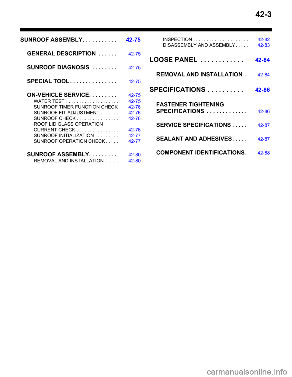
SUNROOF ASSEMBLY . . . . . . . . . . .42-75
GENERAL DESCRIPTION . . . . . .
42-75
SUNROOF DIAGNOSIS . . . . . . . .42-75
SPECIAL TOOL . . . . . . . . . . . . . . .42-75
ON-VEHICLE SERVICE. . . . . . . . .42-75
WATER TEST . . . . . . . . . . . . . . . . . . . . 42-75
SUNROOF TIMER FUNCTION CHECK 42-76
SUNROOF FIT ADJUSTMENT . . . . . . . 42-76
SUNROOF CHECK . . . . . . . . . . . . . . . . 42-76
ROOF LID GLASS OPERATION
CURRENT CHECK . . . . . . . . . . . . . . . . 42-76
SUNROOF INITIALIZATION . . . . . . . . . 42-77
SUNROOF OPERATION CHECK . . . . . 42-77
SUNROOF ASSEMBLY. . . . . . . . .42-80
REMOVAL AND INSTALLATION . . . . . 42-80INSPECTION . . . . . . . . . . . . . . . . . . . . . 42-82
DISASSEMBLY AND ASSEMBLY . . . . . 42-83
LOOSE PANEL . . . . . . . . . . . . 42-84
REMOVAL AND INSTALLATION .
42-84
SPECIFICATIONS . . . . . . . . . . 42-86
FASTENER TIGHTENING
SPECIFICATIONS . . . . . . . . . . . . .
42-86
SERVICE SPECIFICATIONS . . . . .42-87
SEALANT AND ADHESIVES . . . . .42-87
COMPONENT IDENTIFICATIONS .42-88