Gauge MITSUBISHI 380 2005 User Guide
[x] Cancel search | Manufacturer: MITSUBISHI, Model Year: 2005, Model line: 380, Model: MITSUBISHI 380 2005Pages: 1500, PDF Size: 47.87 MB
Page 942 of 1500
ON-VEHICLE SERVICE
ENGINE COOLING14-27
RADIATOR CAP PRESSURE CHECKM1141001300419
NOTE: Be sure that the cap is clean before testing. Rust or
other foreign material on the cap seal will cause an improper
reading.
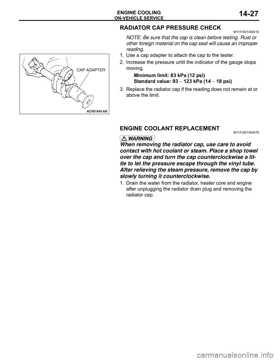
1. Use a cap adapter to attach the cap to the tester.
2. Increase the pressure until the indicator of the gauge stops
moving.
Minimum limit: 83 kPa (12 psi)
Standard value: 93
123 kPa (14 18 psi)
3. Replace the radiator cap if the reading does not remain at or
above the limit.
ENGINE COOLANT REPLACEMENTM1141001200478
When removing the radiator cap, use care to avoid
contact with hot coolant or steam. Place a shop towel
over the cap and turn the cap counterclockwise a lit-
tle to let the pressure escape through the vinyl tube.
After relieving the steam pressure, remove the cap by
slowly turning it counterclockwise.
1. Drain the water from the radiator, heater core and engine
after unplugging the radiator drain plug and removing the
radiator cap.
Page 968 of 1500
INTAKE MANIFOLD
INTAKE AND EXHAUST15-9
>>C<< FUEL HIGH-PRESSURE HOSE
INSTALLATION
Be careful not to allow any engine oil to enter the fuel
rail.
Be careful not to bend the fuel high-pressure hose as it
is made of plastics.
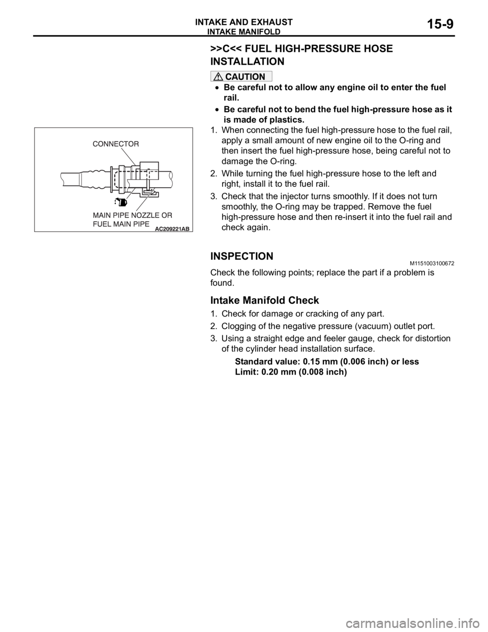
1. When connecting the fuel high-pressure hose to the fuel rail,
apply a small amount of new engine oil to the O-ring and
then insert the fuel high-pressure hose, being careful not to
damage the O-ring.
2. While turning the fuel high-pressure hose to the left and
right, install it to the fuel rail.
3. Check that the injector turns smoothly. If it does not turn
smoothly, the O-ring may be trapped. Remove the fuel
high-pressure hose and then re-insert it into the fuel rail and
check again.
INSPECTIONM1151003100672
Check the following points; replace the part if a problem is
found.
.
Intake Manifold Check
1. Check for damage or cracking of any part.
2. Clogging of the negative pressure (vacuum) outlet port.
3. Using a straight edge and feeler gauge, check for distortion
of the cylinder head installation surface.
Standard value: 0.15 mm (0.006 inch) or less
Limit: 0.20 mm (0.008 inch)
Page 972 of 1500
EXHAUST MANIFOLD
INTAKE AND EXHAUST15-13
>>B<< LEFT BANK HEATED OXYGEN SENSOR
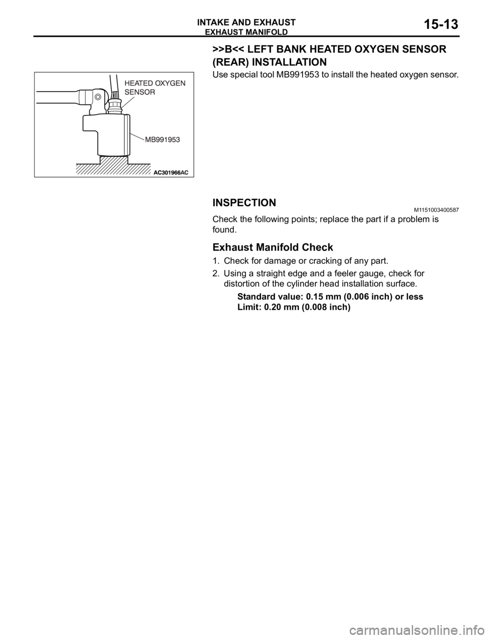
(REAR) INSTALLATION
Use special tool MB991953 to install the heated oxygen sensor.
INSPECTIONM1151003400587
Check the following points; replace the part if a problem is
found.
.
Exhaust Manifold Check
1. Check for damage or cracking of any part.
2. Using a straight edge and a feeler gauge, check for
distortion of the cylinder head installation surface.
Standard value: 0.15 mm (0.006 inch) or less
Limit: 0.20 mm (0.008 inch)
Page 1001 of 1500
Page 1005 of 1500
STARTING SYSTEM
ENGINE ELECTRICAL16-28
INSPECTIONM1162001300102.
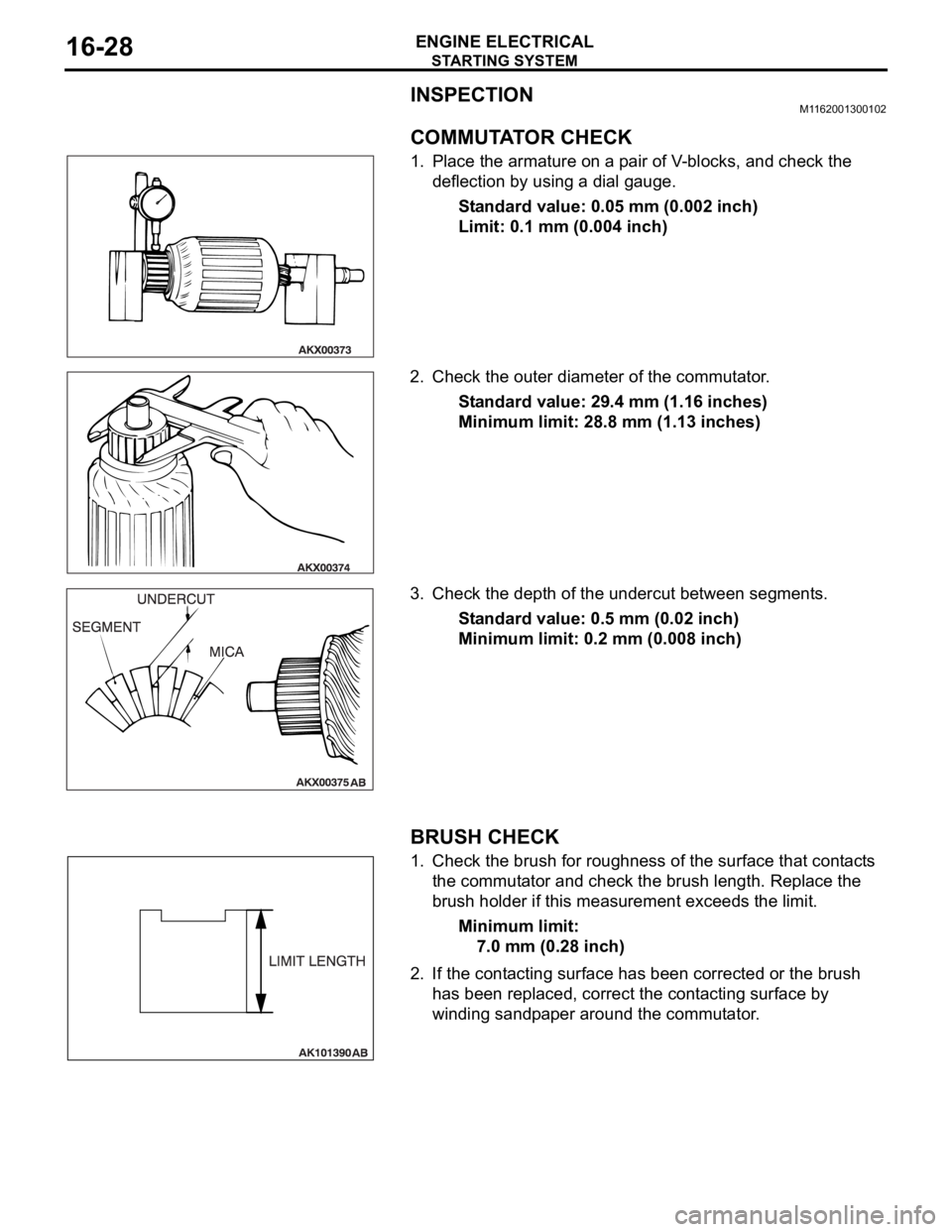
COMMUTATOR CHECK
1. Place the armature on a pair of V-blocks, and check the
deflection by using a dial gauge.
Standard value: 0.05 mm (0.002 inch)
Limit: 0.1 mm (0.004 inch)
2. Check the outer diameter of the commutator.
Standard value: 29.4 mm (1.16 inches)
Minimum limit: 28.8 mm (1.13 inches)
3. Check the depth of the undercut between segments.
Standard value: 0.5 mm (0.02 inch)
Minimum limit: 0.2 mm (0.008 inch)
.
BRUSH CHECK
1. Check the brush for roughness of the surface that contacts
the commutator and check the brush length. Replace the
brush holder if this measurement exceeds the limit.
Minimum limit:
7.0 mm (0.28 inch)
2. If the contacting surface has been corrected or the brush
has been replaced, correct the contacting surface by
winding sandpaper around the commutator.
.
Page 1175 of 1500
BASIC BRAKE SYSTEM DIAGNOSIS
BASIC BRAKE SYSTEM35A-10
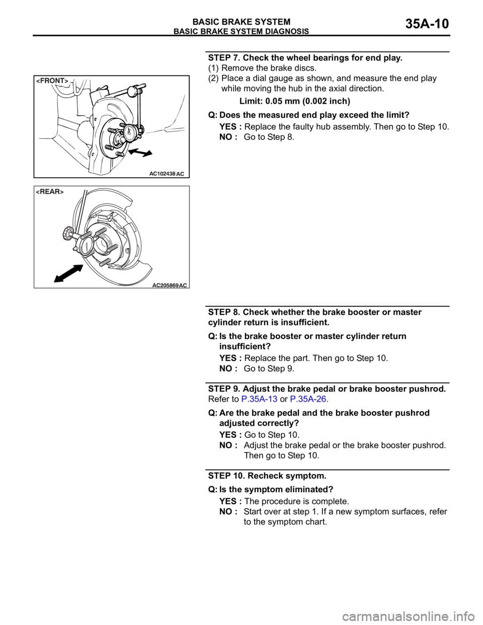
STEP 7. Check the wheel bearings for end play.
(1) Remove the brake discs.
(2) Place a dial gauge as shown, and measure the end play
while moving the hub in the axial direction.
Limit: 0.05 mm (0.002 inch)
Q: Does the measured end play exceed the limit?
YES : Replace the faulty hub assembly. Then go to Step 10.
NO : Go to Step 8.
STEP 8. Check whether the brake booster or master
cylinder return is insufficient.
Q: Is the brake booster or master cylinder return
insufficient?
YES : Replace the part. Then go to Step 10.
NO : Go to Step 9.
STEP 9. Adjust the brake pedal or brake booster pushrod.
Refer to P.35A-13 or P.35A-26.
Q: Are the brake pedal and the brake booster pushrod
adjusted correctly?
YES : Go to Step 10.
NO : Adjust the brake pedal or the brake booster pushrod.
Then go to Step 10.
STEP 10. Recheck symptom.
Q: Is the symptom eliminated?
YES : The procedure is complete.
NO : Start over at step 1. If a new symptom surfaces, refer
to the symptom chart.
Page 1177 of 1500
SPECIAL TOOLS
BASIC BRAKE SYSTEM35A-12
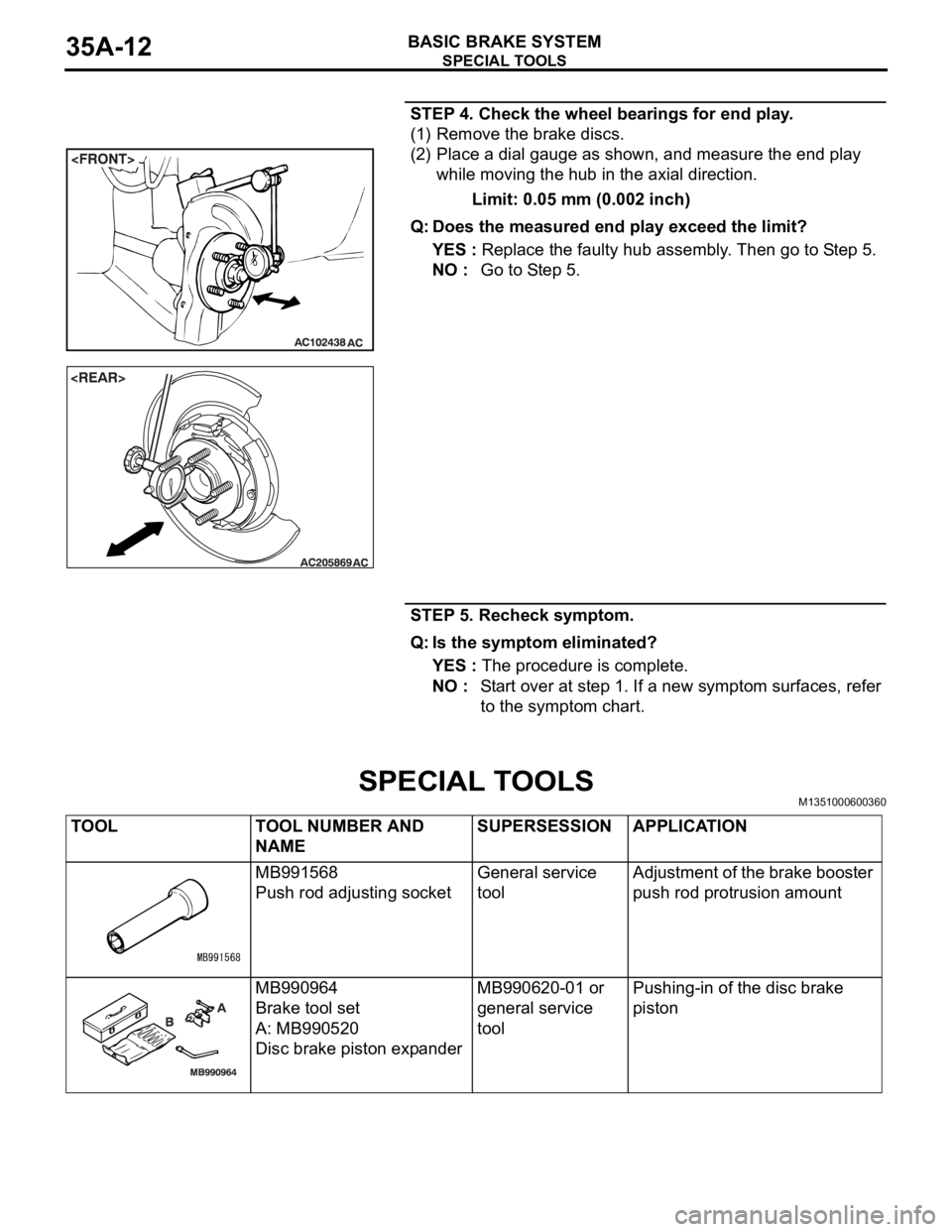
STEP 4. Check the wheel bearings for end play.
(1) Remove the brake discs.
(2) Place a dial gauge as shown, and measure the end play
while moving the hub in the axial direction.
Limit: 0.05 mm (0.002 inch)
Q: Does the measured end play exceed the limit?
YES : Replace the faulty hub assembly. Then go to Step 5.
NO : Go to Step 5.
STEP 5. Recheck symptom.
Q: Is the symptom eliminated?
YES : The procedure is complete.
NO : Start over at step 1. If a new symptom surfaces, refer
to the symptom chart.
SPECIAL TOOLSM1351000600360
TOOL TOOL NUMBER AND
NAMESUPERSESSION APPLICATION
MB991568
Push rod adjusting socketGeneral service
toolAdjustment of the brake booster
push rod protrusion amount
MB990964
Brake tool set
A: MB990520
Disc brake piston expanderMB990620-01 or
general service
toolPushing-in of the disc brake
piston
Page 1187 of 1500
ON-VEHICLE SERVICE
BASIC BRAKE SYSTEM35A-22
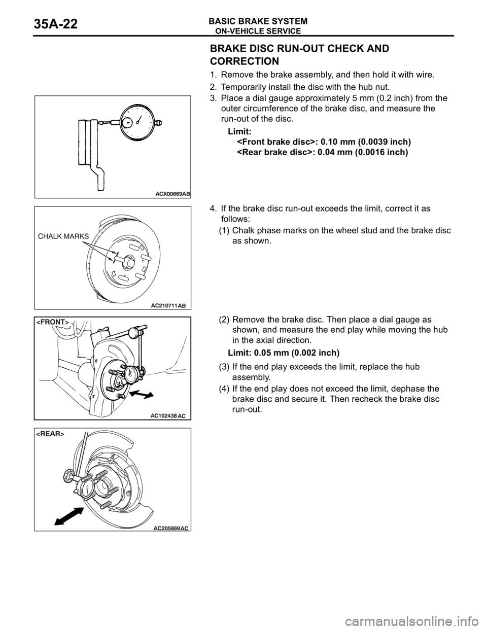
BRAKE DISC RUN-OUT CHECK AND
CORRECTION
1. Remove the brake assembly, and then hold it with wire.
2. Temporarily install the disc with the hub nut.
3. Place a dial gauge approximately 5 mm (0.2 inch) from the
outer circumference of the brake disc, and measure the
run-out of the disc.
Limit:
4. If the brake disc run-out exceeds the limit, correct it as
follows:
(1) Chalk phase marks on the wheel stud and the brake disc
as shown.
(2) Remove the brake disc. Then place a dial gauge as
shown, and measure the end play while moving the hub
in the axial direction.
Limit: 0.05 mm (0.002 inch)
(3) If the end play exceeds the limit, replace the hub
assembly.
(4) If the end play does not exceed the limit, dephase the
brake disc and secure it. Then recheck the brake disc
run-out.
Page 1262 of 1500
MAINTENANCE SERVICE
GENERAL00-41
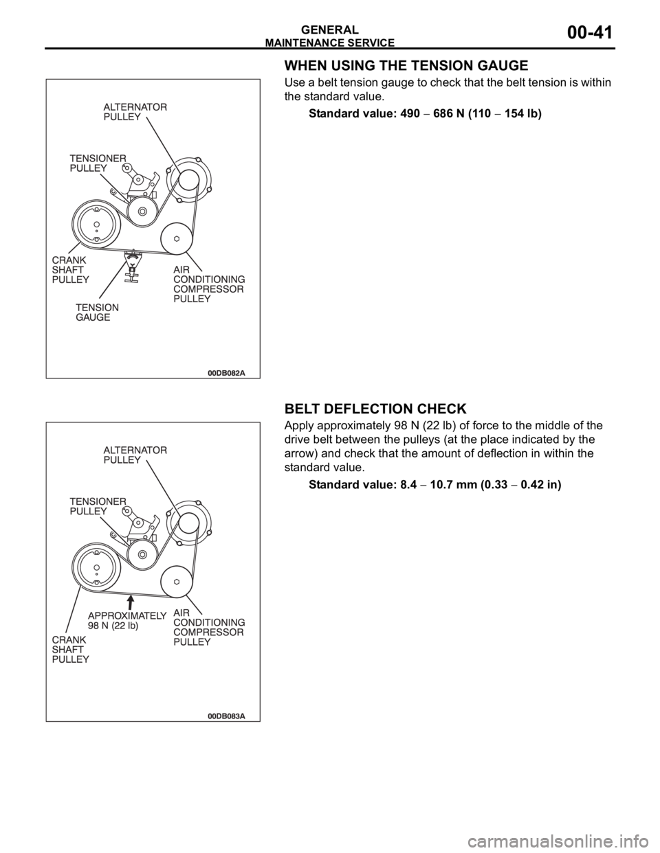
WHEN USING THE TENSION GAUGE
Use a belt tension gauge to check that the belt tension is within
the standard value.
Standard value: 490
686 N (110 154 lb)
.
BELT DEFLECTION CHECK
Apply approximately 98 N (22 lb) of force to the middle of the
drive belt between the pulleys (at the place indicated by the
arrow) and check that the amount of deflection in within the
standard value.
Standard value: 8.4
10.7 mm (0.33 0.42 in)
Page 1264 of 1500
MAINTENANCE SERVICE
GENERAL00-43
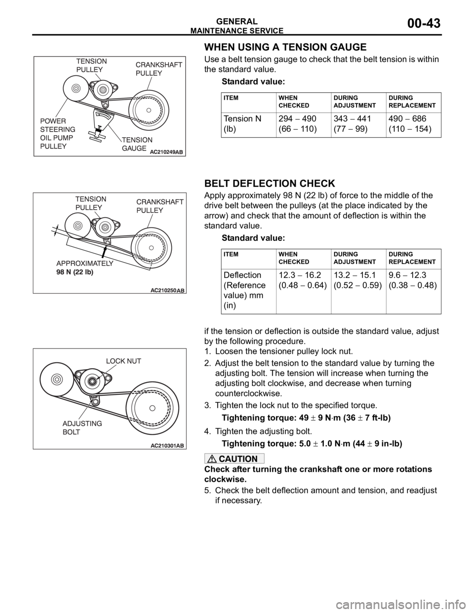
WHEN USING A TENSION GAUGE
Use a belt tension gauge to check that the belt tension is within
the standard value.
Standard value:
.
BELT DEFLECTION CHECK
Apply approximately 98 N (22 lb) of force to the middle of the
drive belt between the pulleys (at the place indicated by the
arrow) and check that the amount of deflection is within the
standard value.
Standard value:
.if the tension or deflection is outside the standard value, adjust
by the following procedure.
1. Loosen the tensioner pulley lock nut.
2. Adjust the belt tension to the standard value by turning the
adjusting bolt. The tension will increase when turning the
adjusting bolt clockwise, and decrease when turning
counterclockwise.
3. Tighten the lock nut to the specified torque.
Tightening torque: 49
9 Nm (36 7 ft-lb)
4. Tighten the adjusting bolt.
Tightening torque: 5.0
1.0 Nm (44 9 in-lb)
Check after turning the crankshaft one or more rotations
clockwise.
5. Check the belt deflection amount and tension, and readjust
if necessary.
ITEM WHEN
CHECKEDDURING
ADJUSTMENTDURING
REPLACEMENT
Te n s i o n N
(lb)294 490
(66
110)343
441
(77
99)490
686
(110
154)
ITEM WHEN
CHECKEDDURING
ADJUSTMENTDURING
REPLACEMENT
Deflection
(Reference
value) mm
(in)12.3 16.2
(0.48
0.64)13.2
15.1
(0.52
0.59)9.6
12.3
(0.38
0.48)