Gauge MITSUBISHI 380 2005 Owner's Manual
[x] Cancel search | Manufacturer: MITSUBISHI, Model Year: 2005, Model line: 380, Model: MITSUBISHI 380 2005Pages: 1500, PDF Size: 47.87 MB
Page 1420 of 1500

FRONT AXLE DIAGNOSIS
FRONT AXLE26-3
2. Verify that the condition described by the
customer exists.3. Find the malfunction by following the Symptom
Chart.
4. Verify malfunction is eliminated.
SYMPTOM CHARTM1261005700269
SYMPTOM PROCEDURES
INSPECTION PROCEDURE 1: Noise during Wheel Rotation
DIAGNOSIS
STEP 1. Check the wheel bearing end play.
(1) Remove the caliper assembly and suspend it with a wire.
(2) Remove the brake disc from the front hub.
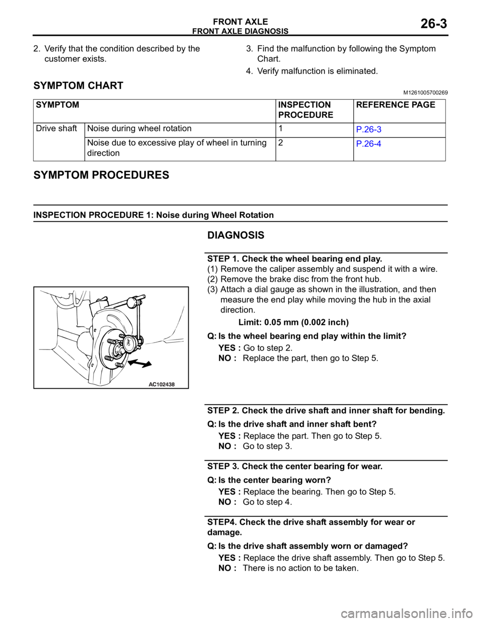
(3) Attach a dial gauge as shown in the illustration, and then
measure the end play while moving the hub in the axial
direction.
Limit: 0.05 mm (0.002 inch)
Q: Is the wheel bearing end play within the limit?
YES : Go to step 2.
NO : Replace the part, then go to Step 5.
STEP 2. Check the drive shaft and inner shaft for bending.
Q: Is the drive shaft and inner shaft bent?
YES : Replace the part. Then go to Step 5.
NO : Go to step 3.
STEP 3. Check the center bearing for wear.
Q: Is the center bearing worn?
YES : Replace the bearing. Then go to Step 5.
NO : Go to step 4.
STEP4. Check the drive shaft assembly for wear or
damage.
Q: Is the drive shaft assembly worn or damaged?
YES : Replace the drive shaft assembly. Then go to Step 5.
NO : There is no action to be taken. SYMPTOM INSPECTION
PROCEDUREREFERENCE PAGE
Drive shaft Noise during wheel rotation 1
P.26-3
Noise due to excessive play of wheel in turning
direction2
P.26-4
Page 1425 of 1500

ON-VEHICLE SERVICE
FRONT AXLE26-8
ON-VEHICLE SERVICE
WHEEL BEARING END PLAY CHECKM1261000900246
1. Remove the caliper assembly and suspend it with a wire.
2. Remove the brake disc from the front hub.
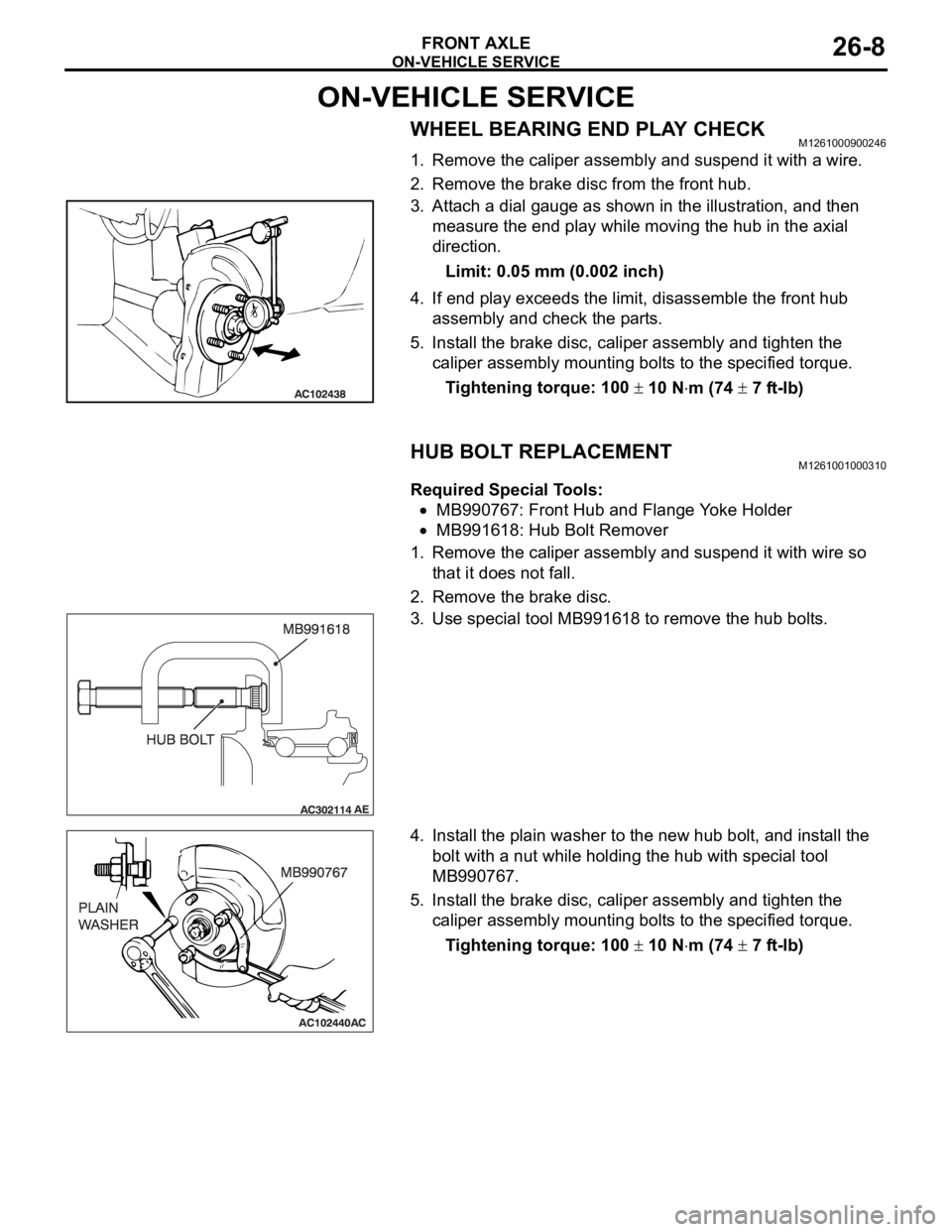
3. Attach a dial gauge as shown in the illustration, and then
measure the end play while moving the hub in the axial
direction.
Limit: 0.05 mm (0.002 inch)
4. If end play exceeds the limit, disassemble the front hub
assembly and check the parts.
5. Install the brake disc, caliper assembly and tighten the
caliper assembly mounting bolts to the specified torque.
Tightening torque: 100
10 Nm (74 7 ft-lb)
HUB BOLT REPLACEMENTM1261001000310
Required Special Tools:
MB990767: Front Hub and Flange Yoke Holder
MB991618: Hub Bolt Remover
1. Remove the caliper assembly and suspend it with wire so
that it does not fall.
2. Remove the brake disc.
3. Use special tool MB991618 to remove the hub bolts.
4. Install the plain washer to the new hub bolt, and install the
bolt with a nut while holding the hub with special tool
MB990767.
5. Install the brake disc, caliper assembly and tighten the
caliper assembly mounting bolts to the specified torque.
Tightening torque: 100
10 Nm (74 7 ft-lb)
Page 1450 of 1500

REAR AXLE DIAGNOSIS
REAR AXLE27-3
SYMPTOM PROCEDURESM1271004400222
INSPECTION PROCEDURE 1: Abnormal Noise
DIAGNOSIS
STEP 1. Check the rear hub assembly installation bolts for
looseness.
Q: Are the rear hub assembly installation bolts loosened?
YES : Tighten the rear hub assembly installation bolts to the
specified torque 73
7 Nm (54 5 ft-lb). Then go to
St e p 4 .
NO : Go to Step 2.
STEP 2. Check the wheel bearing end play.
(1) Remove the caliper assembly, and suspend the caliper
assembly with a wire and remove the brake disc.
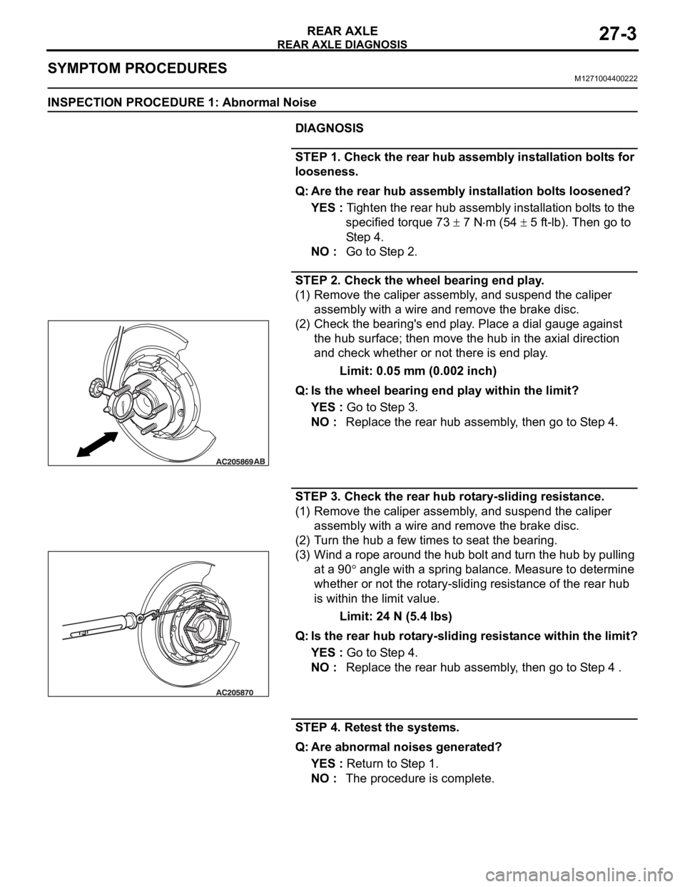
(2) Check the bearing's end play. Place a dial gauge against
the hub surface; then move the hub in the axial direction
and check whether or not there is end play.
Limit: 0.05 mm (0.002 inch)
Q: Is the wheel bearing end play within the limit?
YES : Go to Step 3.
NO : Replace the rear hub assembly, then go to Step 4.
STEP 3. Check the rear hub rotary-sliding resistance.
(1) Remove the caliper assembly, and suspend the caliper
assembly with a wire and remove the brake disc.
(2) Turn the hub a few times to seat the bearing.
(3) Wind a rope around the hub bolt and turn the hub by pulling
at a 90
angle with a spring balance. Measure to determine
whether or not the rotary-sliding resistance of the rear hub
is within the limit value.
Limit: 24 N (5.4 lbs)
Q: Is the rear hub rotary-sliding resistance within the limit?
YES : Go to Step 4.
NO : Replace the rear hub assembly, then go to Step 4 .
STEP 4. Retest the systems.
Q: Are abnormal noises generated?
YES : Return to Step 1.
NO : The procedure is complete.
Page 1451 of 1500

SPECIAL TOOLS
REAR AXLE27-4
SPECIAL TOOLSM1271000600525
ON-VEHICLE SERVICE
WHEEL BEARING END PLAY CHECKM1271000900474
1. Remove the caliper assembly, and suspend the caliper
assembly with a wire and remove the brake disc.
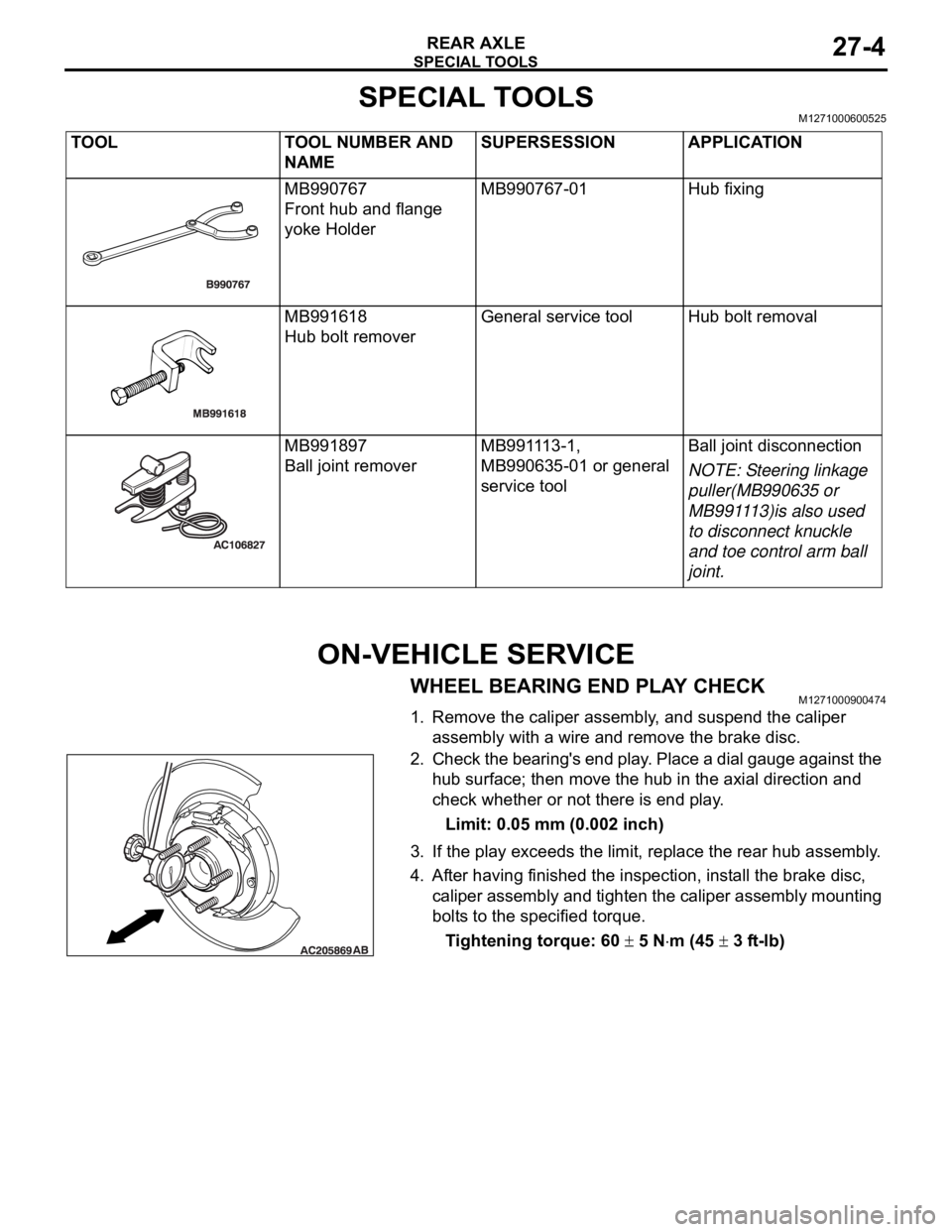
2. Check the bearing's end play. Place a dial gauge against the
hub surface; then move the hub in the axial direction and
check whether or not there is end play.
Limit: 0.05 mm (0.002 inch)
3. If the play exceeds the limit, replace the rear hub assembly.
4. After having finished the inspection, install the brake disc,
caliper assembly and tighten the caliper assembly mounting
bolts to the specified torque.
Tightening torque: 60
5 Nm (45 3 ft-lb) TOOL TOOL NUMBER AND
NAMESUPERSESSION APPLICATION
MB990767
Front hub and flange
yoke HolderMB990767-01 Hub fixing
MB991618
Hub bolt removerGeneral service tool Hub bolt removal
MB991897
Ball joint removerMB991113-1,
MB990635-01 or general
service toolBall joint disconnection
NOTE: Steering linkage
puller(MB990635 or
MB991113)is also used
to disconnect knuckle
and toe control arm ball
joint.
Page 1486 of 1500
![MITSUBISHI 380 2005 Owners Manual AUTOMATIC TRANSMISSION DIAGNOSIS
AUTOMATIC TRANSMISSION23A-27
3. Connect the special tools (3.0 MPa (427 psi) oil pressure
gauge [MD998330] and adapters [MD998332, MD998900])
to each pressure discha MITSUBISHI 380 2005 Owners Manual AUTOMATIC TRANSMISSION DIAGNOSIS
AUTOMATIC TRANSMISSION23A-27
3. Connect the special tools (3.0 MPa (427 psi) oil pressure
gauge [MD998330] and adapters [MD998332, MD998900])
to each pressure discha](/img/19/57086/w960_57086-1485.png)
AUTOMATIC TRANSMISSION DIAGNOSIS
AUTOMATIC TRANSMISSION23A-27
3. Connect the special tools (3.0 MPa (427 psi) oil pressure
gauge [MD998330] and adapters [MD998332, MD998900])
to each pressure discharge port.
NOTE: .
2ND: Second brake pressure port
UD: Underdrive clutch pressure port
LR: Low-reverse brake pressure port
DR: Torque converter release pressure port
DA: Torque converter apply pressure port
RV: Reverse clutch pressure port
OD: Overdrive clutch pressure port
DIR: Direct clutch pressure port
RED: Reduction clutch pressure port
4. Restart the engine.
5. Check that there are no leaks around the special tool port
adapters.
6. Measure the hydraulic pressure at each port under the
conditions given in the standard hydraulic pressure table,
and check that the measured values are within the standard
value ranges.
7. If the pressure is not within the standard value, stop the
engine and refer to the hydraulic pressure test diagnosis
table.
8. Remove the O-ring from the port plug and replace it.
9. Remove the special tool, and install the plugs to the
hydraulic pressure ports.
10.Start the engine and check that there are no leaks around
the plugs.