Transmitter MITSUBISHI 380 2005 User Guide
[x] Cancel search | Manufacturer: MITSUBISHI, Model Year: 2005, Model line: 380, Model: MITSUBISHI 380 2005Pages: 1500, PDF Size: 47.87 MB
Page 202 of 1500
SYMPTOM PROCEDURES
SIMPLIFIED WIRING SYSTEM (SWS)54B-202
INSPECTION PROCEDURE E-3: Keyless Entry System: Encrypted code cannot be registered.
.
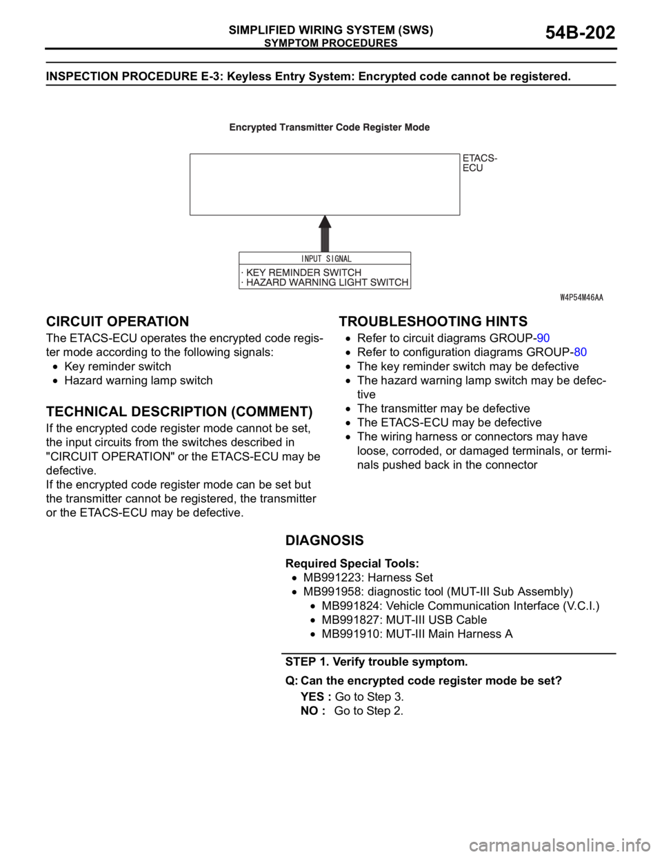
CIRCUIT OPERATION
The ETACS-ECU operates the encrypted code regis-
ter mode according to the following signals:
Key reminder switch
Hazard warning lamp switch
.
TECHNICAL DESCRIPTION (COMMENT)
If the encrypted code register mode cannot be set,
the input circuits from the switches described in
"CIRCUIT OPERATION" or the ETACS-ECU may be
defective.
If the encrypted code register mode can be set but
the transmitter cannot be registered, the transmitter
or the ETACS-ECU may be defective.
.
TROUBLESHOOTING HINTS
Refer to circuit diagrams GROUP-90
Refer to configuration diagrams GROUP-80
The key reminder switch may be defective
The hazard warning lamp switch may be defec-
tive
The transmitter may be defective
The ETACS-ECU may be defective
The wiring harness or connectors may have
loose, corroded, or damaged terminals, or termi-
nals pushed back in the connector
DIAGNOSIS
Required Special Tools:
MB991223: Harness Set
MB991958: diagnostic tool (MUT-III Sub Assembly)
MB991824: Vehicle Communication Interface (V.C.I.)
MB991827: MUT-III USB Cable
MB991910: MUT-III Main Harness A
STEP 1. Verify trouble symptom.
Q: Can the encrypted code register mode be set?
YES : Go to Step 3.
NO : Go to Step 2.
Page 203 of 1500

SYMPTOM PROCEDURES
SIMPLIFIED WIRING SYSTEM (SWS)54B-203
STEP 2. Check the input signal (by using the pulse check
mode of the monitor).
Check the input signals from the following switches:
Key reminder switch
Hazard warning lamp switch
To prevent damage to diagnostic tool MB991958, always
turn the ignition switch to the "LOCK" (OFF) position
before connecting or disconnecting diagnostic tool
MB991958.
(1) Connect diagnostic tool MB991958.Refer to "How to
connect SWS monitor P.54B-13."
(2) Operate diagnostic tool MB991958 according to the
procedure below to display "Pulse check."
a. Select "Interactive Diagnosis."
b. Select "System select."
c. Select "SWS."
d. Select "Pulse Checking."
(3) Check the switches (see table below) applicable for the
input signal check are operated.
(4) Check diagnostic tool MB991958 sounds or not.
Q: When the key reminder switch and the hazard warning
lamp switch are operated, does diagnostic tool
MB991958 sound in each case?
Buzzer of diagnostic tool MB991958 sounds normally. :
Replace the ETACS-ECU. Verify that the encrypted
code can be registered in the transmitter.
diagnostic tool MB991958 does not sound when the
ignition key is removed and reinserted : Refer to
Inspection Procedure N-1 "ETACS-ECU does not
receive any signal from the key reminder switch
P.54B-432."
diagnostic tool MB991958 does not sound when the
hazard warning lamp switch is turned from "OFF" to
"ON" : Refer to Inspection Procedure N-2 "ETACS-ECU
does not receive any signal from the hazard warning
lamp switch P.54B-436." ITEM NAME CHECK CONDITION
Key reminder switch Remove and reinsert the
ignition key
Hazard warning lamp switch Turn the hazard warning lamp
switch from "OFF" to "ON"
position.
Page 204 of 1500

SYMPTOM PROCEDURES
SIMPLIFIED WIRING SYSTEM (SWS)54B-204
STEP 3. Check the transmitter.
Q: When the transmitter's battery is replaced, can the
encrypted code be registered?
YES : No action is necessary and testing is complete.
NO : Replace the transmitter. If the encrypted code cannot
be registered using the new transmitter, replace the
ETACS-ECU. Verify that the encrypted code can be
registered in the transmitter.
Page 205 of 1500
SYMPTOM PROCEDURES
SIMPLIFIED WIRING SYSTEM (SWS)54B-205
INSPECTION PROCEDURE E-4: Keyless Entry System: The trunk is not opened when the keyless
entry transmitter "TRUNK" button is operated.
.
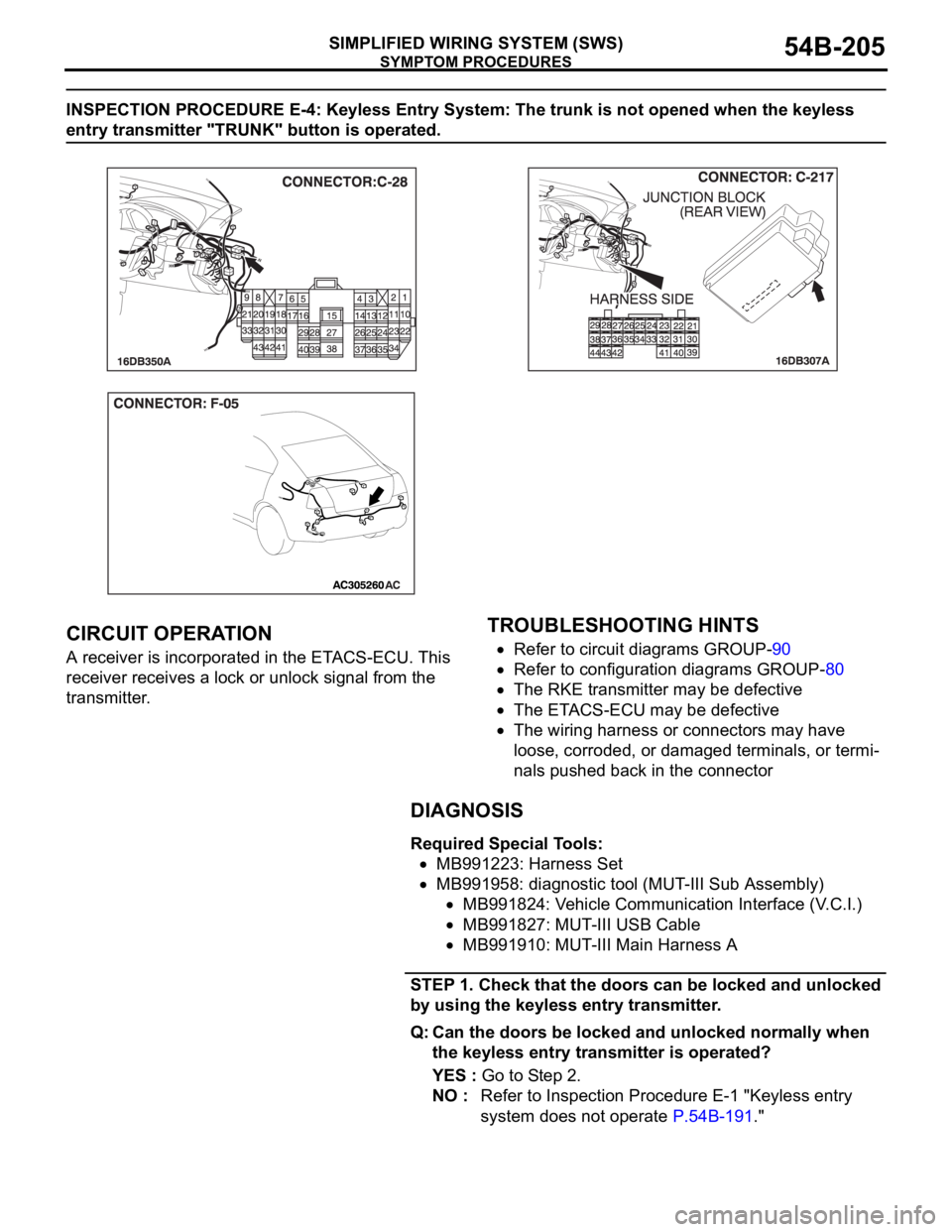
CIRCUIT OPERATION
A receiver is incorporated in the ETACS-ECU. This
receiver receives a lock or unlock signal from the
transmitter.
.
TROUBLESHOOTING HINTS
Refer to circuit diagrams GROUP-90
Refer to configuration diagrams GROUP-80
The RKE transmitter may be defective
The ETACS-ECU may be defective
The wiring harness or connectors may have
loose, corroded, or damaged terminals, or termi-
nals pushed back in the connector
DIAGNOSIS
Required Special Tools:
MB991223: Harness Set
MB991958: diagnostic tool (MUT-III Sub Assembly)
MB991824: Vehicle Communication Interface (V.C.I.)
MB991827: MUT-III USB Cable
MB991910: MUT-III Main Harness A
STEP 1. Check that the doors can be locked and unlocked
by using the keyless entry transmitter.
Q: Can the doors be locked and unlocked normally when
the keyless entry transmitter is operated?
YES : Go to Step 2.
NO : Refer to Inspection Procedure E-1 "Keyless entry
system does not operate P.54B-191."
Page 206 of 1500
SYMPTOM PROCEDURES
SIMPLIFIED WIRING SYSTEM (SWS)54B-206
STEP 2. Check the input signal (by using the pulse check
mode of the monitor).
Check input signals from the transmitter.
To prevent damage to diagnostic tool MB991958, always
turn the ignition switch to the "LOCK" (OFF) position
before connecting or disconnecting diagnostic tool
MB991958.
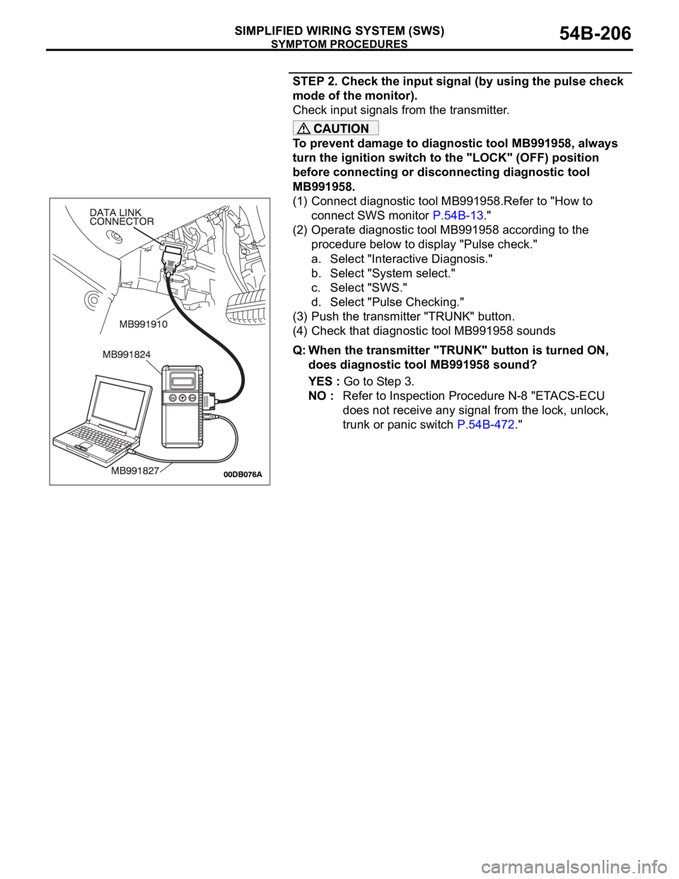
(1) Connect diagnostic tool MB991958.Refer to "How to
connect SWS monitor P.54B-13."
(2) Operate diagnostic tool MB991958 according to the
procedure below to display "Pulse check."
a. Select "Interactive Diagnosis."
b. Select "System select."
c. Select "SWS."
d. Select "Pulse Checking."
(3) Push the transmitter "TRUNK" button.
(4) Check that diagnostic tool MB991958 sounds
Q: When the transmitter "TRUNK" button is turned ON,
does diagnostic tool MB991958 sound?
YES : Go to Step 3.
NO : Refer to Inspection Procedure N-8 "ETACS-ECU
does not receive any signal from the lock, unlock,
trunk or panic switch P.54B-472."
Page 208 of 1500
SYMPTOM PROCEDURES
SIMPLIFIED WIRING SYSTEM (SWS)54B-208
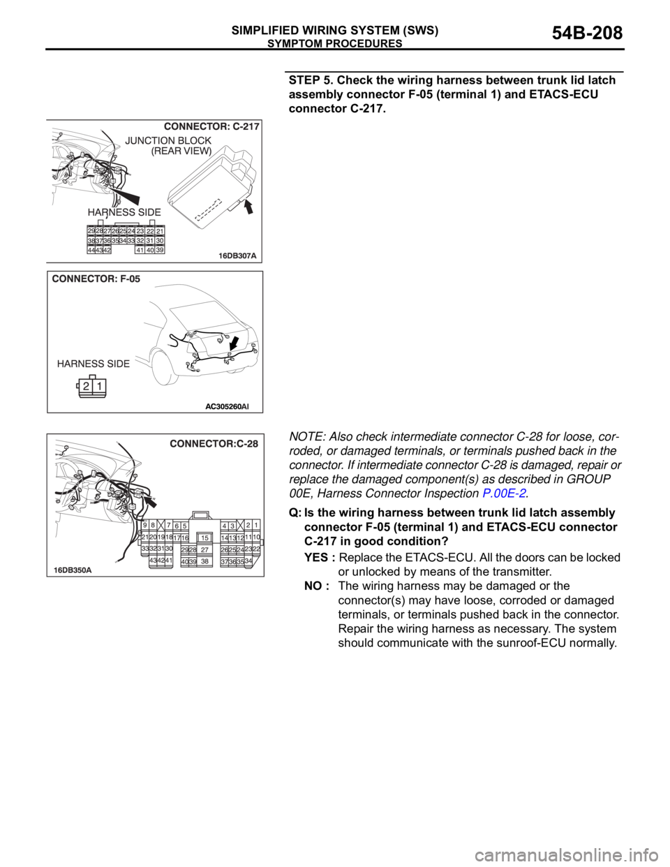
STEP 5. Check the wiring harness between trunk lid latch
assembly connector F-05 (terminal 1) and ETACS-ECU
connector C-217.
NOTE: Also check intermediate connector C-28 for loose, cor-
roded, or damaged terminals, or terminals pushed back in the
connector. If intermediate connector C-28 is damaged, repair or
replace the damaged component(s) as described in GROUP
00E, Harness Connector Inspection P.00E-2.
Q: Is the wiring harness between trunk lid latch assembly
connector F-05 (terminal 1) and ETACS-ECU connector
C-217 in good condition?
YES : Replace the ETACS-ECU. All the doors can be locked
or unlocked by means of the transmitter.
NO : The wiring harness may be damaged or the
connector(s) may have loose, corroded or damaged
terminals, or terminals pushed back in the connector.
Repair the wiring harness as necessary. The system
should communicate with the sunroof-ECU normally.
Page 472 of 1500
INPUT SIGNAL PROCEDURES
SIMPLIFIED WIRING SYSTEM (SWS)54B-472
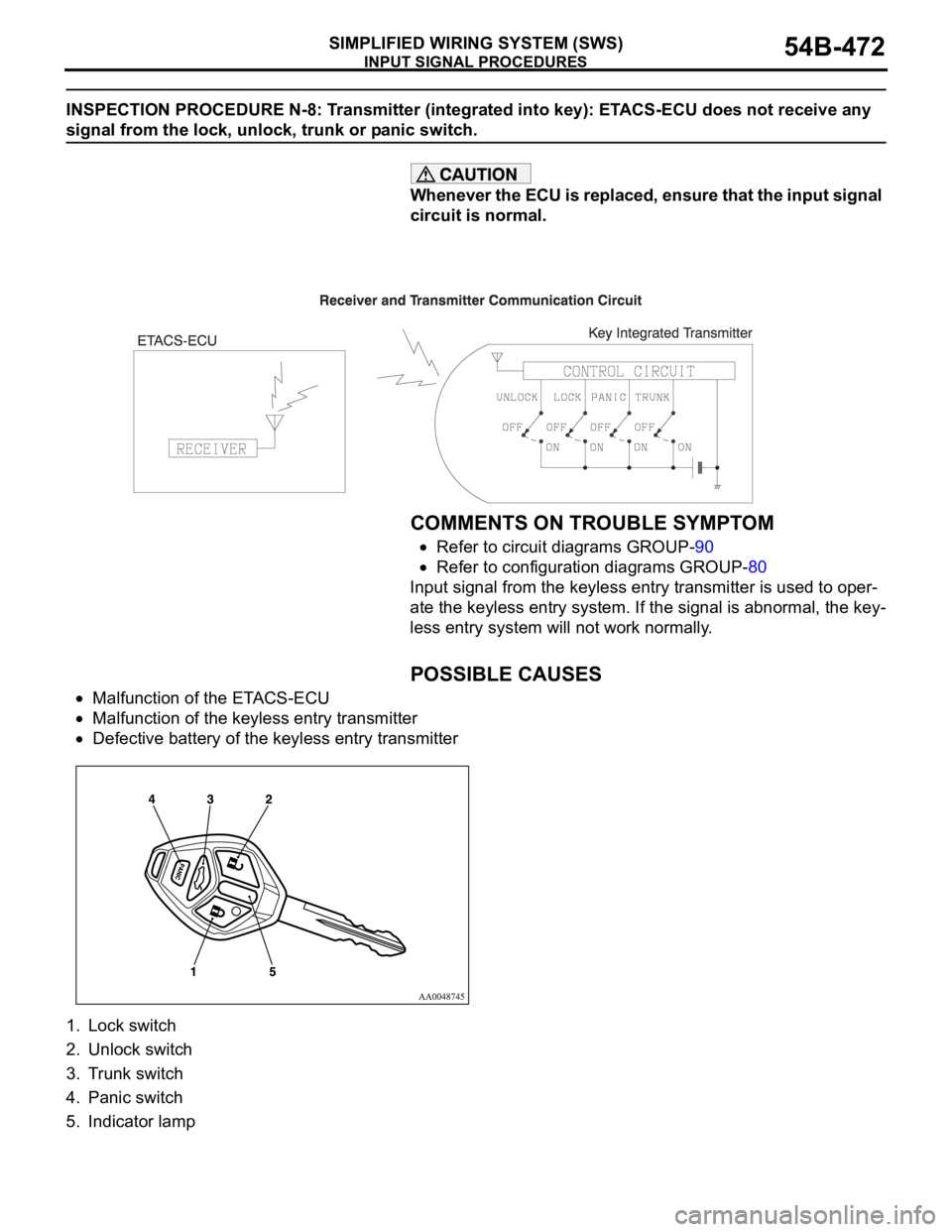
INSPECTION PROCEDURE N-8: Transmitter (integrated into key): ETACS-ECU does not receive any
signal from the lock, unlock, trunk or panic switch.
Whenever the ECU is replaced, ensure that the input signal
circuit is normal.
.
COMMENTS ON TROUBLE SYMPTOM
Refer to circuit diagrams GROUP-90
Refer to configuration diagrams GROUP-80
Input signal from the keyless entry transmitter is used to oper-
ate the keyless entry system. If the signal is abnormal, the key-
less entry system will not work normally.
.
POSSIBLE CAUSES
Malfunction of the ETACS-ECU
Malfunction of the keyless entry transmitter
Defective battery of the keyless entry transmitter
1. Lock switch
2. Unlock switch
3. Trunk switch
4. Panic switch
5. Indicator lamp
Page 473 of 1500

INPUT SIGNAL PROCEDURES
SIMPLIFIED WIRING SYSTEM (SWS)54B-473
DIAGNOSTIC PROCEDURE
Step 1. Pulse check
Check whether the ETACS-ECU receives signal from a trans-
mitter or not. For this check, you should use the 4-button-type
transmitter (integrated with a key), which has already been reg-
istered.
NOTE: For how to register the keyless entry transmitter
encrypted code, refer to GROUP 42
On-vehicle Service
P.42-73.
OK: The MUT-III sounds or the voltmeter needle fluctu-
ates.
Q: Is the check result normal?
YES : Go to Step 2.
NO : Go to Step 4.
Step 2. Check the transmitter battery.
Refer to GROUP 42
Keyless entry system P.42-70.
Q: Is the check result normal?
YES : Go to Step 3.
NO : Replace the keyless entry key integrated transmitter
battery.
Step 3. Register the encrypted code, and then retest the
system.
(1) Register the keyless entry transmitter again.
(2) Check that each signal is received from the keyless entry
transmitter.
Q: Is the check result normal?
YES : The trouble can be an intermittent malfunction (Refer
to GROUP 00
How to Cope with Intermittent
Malfunction P.00-14).
NO : Replace the keyless entry transmitter.
Step 4. Retest the system.
Check that each signal is received from the keyless entry key
integrated transmitter.
Q: Is the check result normal?
YES : The trouble can be an intermittent malfunction (Refer
to GROUP 00
How to Cope with Intermittent
Malfunction P.00-14).
NO : Replace the ETACS-ECU. System switch Check condition
Keyless entry transmitter
"LOCK/UNLOCK" switchWhen the switch is
turned from off to on
Keyless entry transmitter
"Panic" switchWhen the switch is
turned from off to on
Keyless entry transmitter
"Trunk" switchWhen the switch is
turned from off to on
Page 489 of 1500

ON-VEHICLE SERVICE
SIMPLIFIED WIRING SYSTEM (SWS)54B-489
Keyless entry and
power door lock
systemKeyless entry system confirmation
by hornThe horn answerback honking conditions can
be set in the following ways.
a. Horn sounds
b. Horn sounds if doors are already locked
c. Horn does not sound (default)
Keyless entry system confirmation
by turn-signal lampsThe hazard answerback flashing conditions
can be set in the following ways.
a. Locking and unlocking (default)
b. Locking only
c. Unlocking only
d. No indication
Time until automatic relocking after
unlock operation using keyless
entry systemThe timed lock period after unlocking with the
keyless entry transmitter can be set to the
following times.
a. 30 seconds (default)
b. 60 seconds
c. 120 seconds
d. 180 seconds
Unlock operation using keyless
entry system or door keyThe unlocking operations after unlocking with
or without a key can be set in the following
ways.
a. Unlock driver's door on first unlock
operation, and unlock all doors on second
unlock operation (default)
b. Unlock all doors on first unlock operation
Buzzers Turn-signal buzzer The turn-signal buzzer function can be
activated or deactivated. (OFF by default)
Door-ajar warning buzzer The door ajar warning buzzer function can be
activated or deactivated (ON by default).
Default Initialization of above mentioned functions ITEM (multi-center display) ADJUSTMENT DETAILS
Page 1069 of 1500
BODY42-2
DOOR . . . . . . . . . . . . . . . . . . . . . . . . .42-23
GENERAL DESCRIPTION . . . . . .
42-23
CENTRAL DOOR LOCKING SYSTEM
DIAGNOSIS . . . . . . . . . . . . . . . . . . . . . . 42-23
POWER WINDOW DIAGNOSIS . . . . . . 42-23
DOOR DIAGNOSIS . . . . . . . . . . . . . . . . 42-23
INTRODUCTION TO GLASS AND DOOR
DIAGNOSIS . . . . . . . . . . . . . . . . . . . . . . 42-23
GLASS AND DOOR DIAGNOSTIC
TROUBLESHOOTING STRATEGY . . . 42-23
SYMPTOM CHART . . . . . . . . . . . . . . . . 42-24
SYMPTOM PROCEDURES . . . . . . . . . 42-24
HOW TO LOCATE WIND NOISE . . . . . 42-27
SPECIAL TOOLS. . . . . . . . . . . . . .42-28
ON-VEHICLE SERVICE. . . . . . . . .42-30
DOOR FIT ADJUSTMENT. . . . . . . . . . . 42-30
DOOR WINDOW GLASS ADJUSTMENT42-31
GLASS SLIDING MECHANISM CHECK
AND ADJUSTMENT . . . . . . . . . . . . . . . 42-32
POWER WINDOW TIMER FUNCTION
CHECK . . . . . . . . . . . . . . . . . . . . . . . . . 42-32
POWER WINDOW OPERATING
CURRENT CHECK . . . . . . . . . . . . . . . . 42-33
POWER WINDOW RELAY CHECK . . . 42-33
CIRCUIT BREAKER (INCORPORATED IN
THE POWER WINDOW MOTOR)
INSPECTION . . . . . . . . . . . . . . . . . . . . . 42-34
POWER WINDOW CHECK . . . . . . . . . . 42-34
CENTRAL DOOR LOCKING SYSTEM
INSPECTION . . . . . . . . . . . . . . . . . . . . . 42-34
DOOR OUTSIDE HANDLE PLAY CHECK42-35
DOOR INSIDE HANDLE PLAY CHECK 42-35
DOOR ASSEMBLY . . . . . . . . . . . .42-37
REMOVAL AND INSTALLATION . . . . . 42-37
INSPECTION . . . . . . . . . . . . . . . . . . . . . 42-38
DOOR GLASS AND REGULATOR42-39
REMOVAL AND INSTALLATION . . . . . 42-39
INSPECTION . . . . . . . . . . . . . . . . . . . . . 42-43
DOOR HANDLE AND LATCH . . . .42-46
REMOVAL AND INSTALLATION . . . . . 42-46
INSPECTION . . . . . . . . . . . . . . . . . . . . . 42-49
WINDOW GLASS RUNCHANNEL
AND DOOR OPENING
WEATHERSTRIP . . . . . . . . . . . . . .
42-52
REMOVAL AND INSTALLATION . . . . . . 42-52
TRUNK LID. . . . . . . . . . . . . . . . 42-60
TRUNK LID DIAGNOSIS . . . . . . . .
42-60
INTRODUCTION TO TRUNK LID
DIAGNOSIS . . . . . . . . . . . . . . . . . . . . . . 42-60
TRUNK LID DIAGNOSTIC
TROUBLESHOOTING STRATEGY . . . . 42-60
SYMPTOM CHART . . . . . . . . . . . . . . . . 42-60
SYMPTOM PROCEDURES . . . . . . . . . . 42-60
ON-VEHICLE SERVICE . . . . . . . . .42-61
ADJUSTMENT OF CLEARANCE
AROUND TRUNK LID . . . . . . . . . . . . . . 42-61
TRUNK LID LATCH ADJUSTMENT. . . . 42-61
TRUNK LID HEIGHT ADJUSTMENT . . . 42-62
TRUNK LID . . . . . . . . . . . . . . . . . . .42-63
REMOVAL AND INSTALLATION . . . . . . 42-63
INSPECTION . . . . . . . . . . . . . . . . . . . . . 42-65
KEYLESS ENTRY SYSTEM 42-67
GENERAL DESCRIPTION . . . . . . .
42-67
KEYLESS ENTRY SYSTEM
DIAGNOSIS . . . . . . . . . . . . . . . . . .
42-68
SPECIAL TOOL . . . . . . . . . . . . . . .42-68
ON-VEHICLE SERVICE . . . . . . . . .42-69
TRANSMITTER BATTERY CHECK . . . . 42-69
HOW TO REPLACE THE TRANSMITTER
BATTERY . . . . . . . . . . . . . . . . . . . . . . . . 42-70
KEYLESS ENTRY SYSTEM INSPECTION42-71
KEYLESS ENTRY SYSTEM TIMER LOCK
FUNCTION INSPECTION . . . . . . . . . . . 42-71
ENABLING/DISABLING THE
ANSWERBACK FUNCTION . . . . . . . . . 42-72
HOW TO REGISTER SECRET CODE . 42-73
Continued on next page