ad blue MITSUBISHI 380 2005 Workshop Manual
[x] Cancel search | Manufacturer: MITSUBISHI, Model Year: 2005, Model line: 380, Model: MITSUBISHI 380 2005Pages: 1500, PDF Size: 47.87 MB
Page 532 of 1500
FRONT SEAT TRIM COVER
INTERIOR52A-43
FRONT SEAT TRIM COVER
REMOVAL AND FITMENT
REMOVAL
.
1. Remove seat from vehicle and cushion or seat back
assembly as required. Remove all seat plastic covers etc.
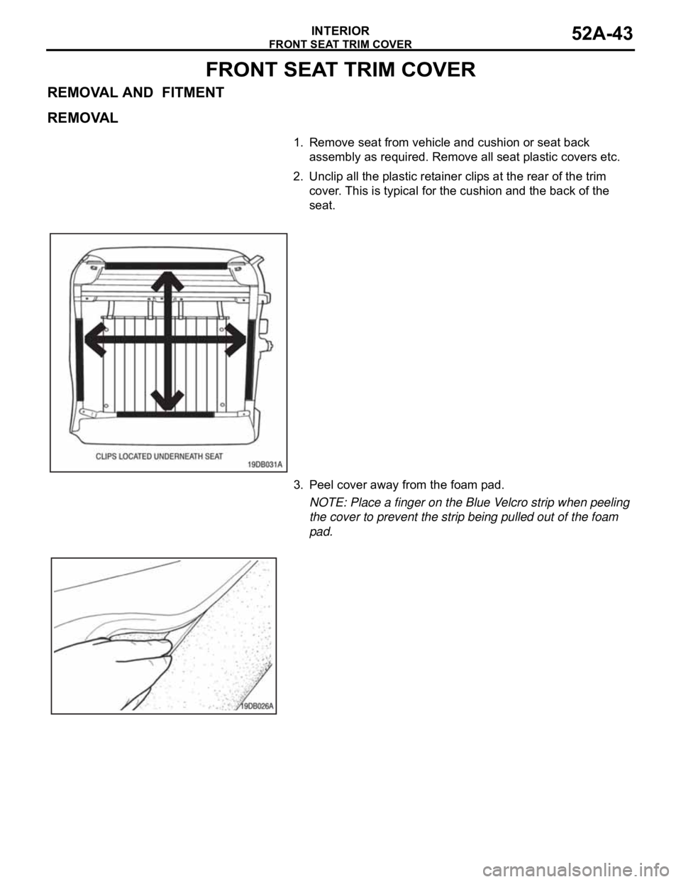
2. Unclip all the plastic retainer clips at the rear of the trim
cover. This is typical for the cushion and the back of the
seat.
3. Peel cover away from the foam pad.
NOTE: Place a finger on the Blue Velcro strip when peeling
the cover to prevent the strip being pulled out of the foam
pad.
Page 535 of 1500
REAR SEAT CUSHION TRIM COVER
INTERIOR52A-46
REAR SEAT CUSHION TRIM COVER
REMOVAL AND FITMENT
REAR SEAT CUSHION TRIM REMOVAL
.
1. Remove rear seat cushion from vehicle.
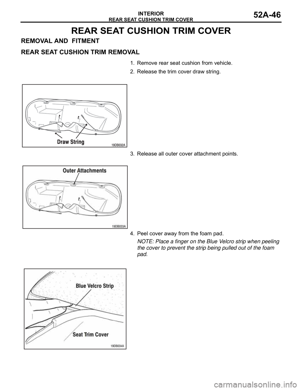
2. Release the trim cover draw string.
3. Release all outer cover attachment points.
4. Peel cover away from the foam pad.
NOTE: Place a finger on the Blue Velcro strip when peeling
the cover to prevent the strip being pulled out of the foam
pad.
Page 539 of 1500
REAR SEAT BACK TRIM COVER
INTERIOR52A-50
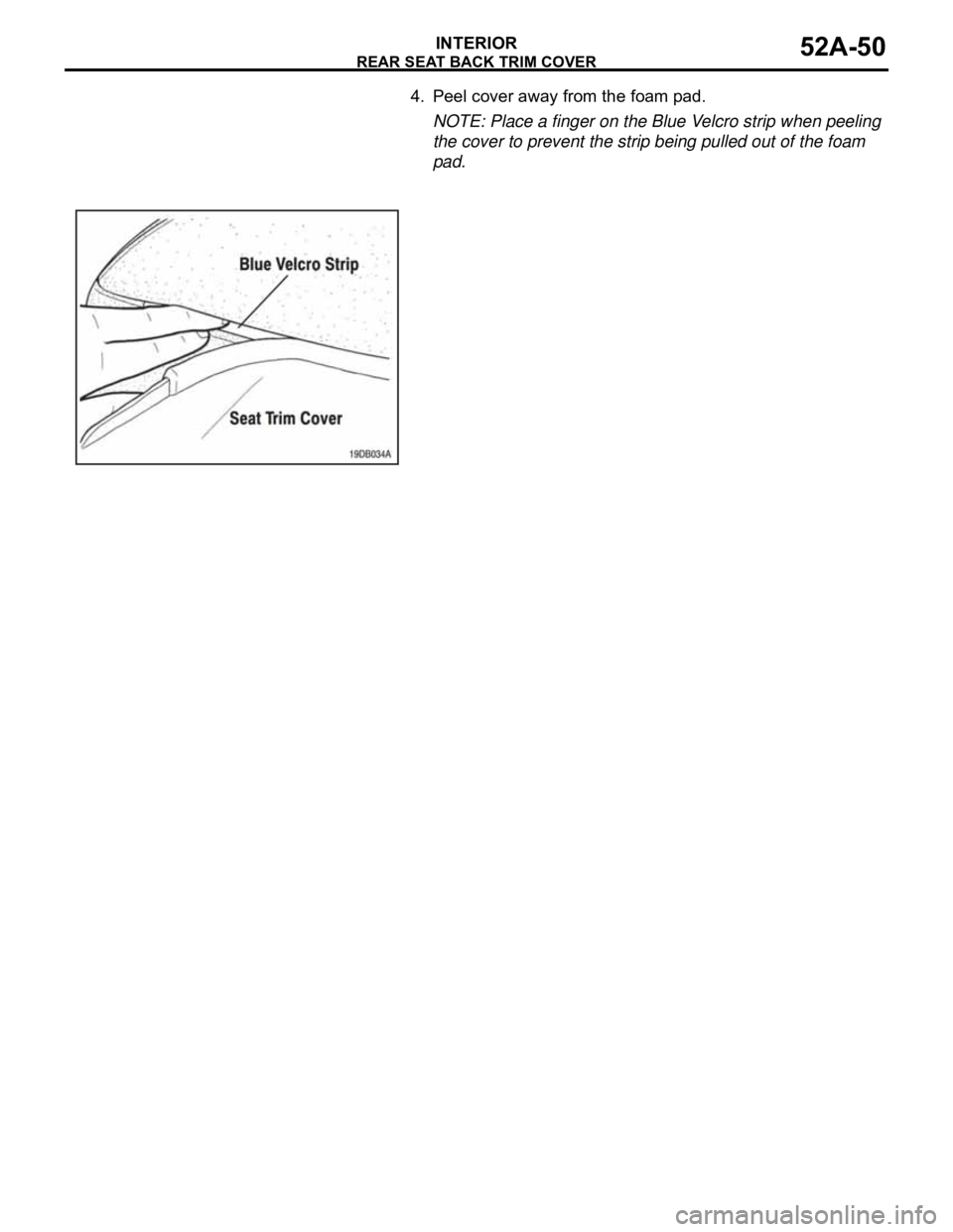
4. Peel cover away from the foam pad.
NOTE: Place a finger on the Blue Velcro strip when peeling
the cover to prevent the strip being pulled out of the foam
pad.
Page 585 of 1500
HOW TO READ CIRCUIT DIAGRAMS
CIRCUIT DIAGRAMS90-8
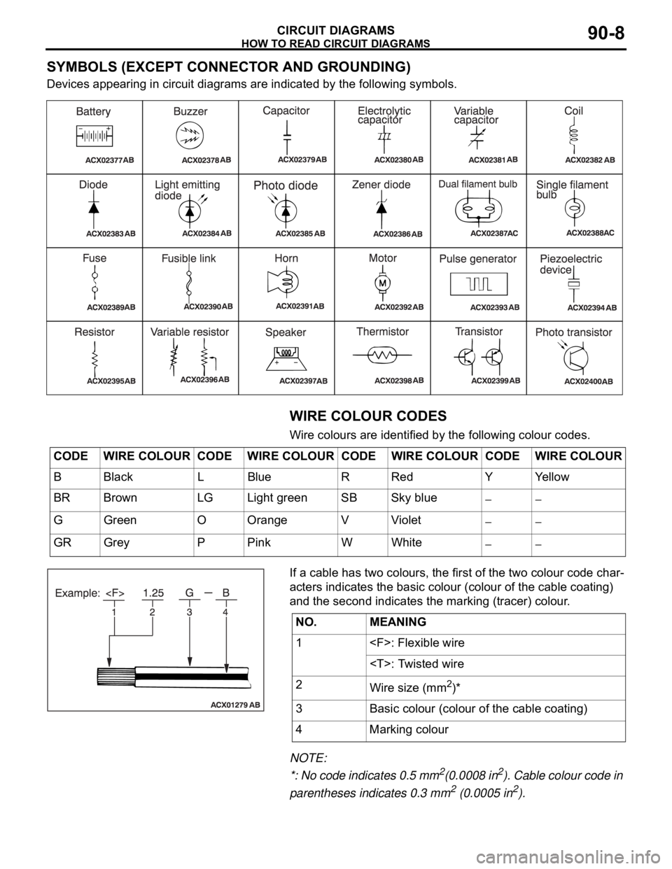
SYMBOLS (EXCEPT CONNECTOR AND GROUNDING)
Devices appearing in circuit diagrams are indicated by the following symbols.
WIRE COLOUR CODES
Wire colours are identified by the following colour codes.
If a cable has two colours, the first of the two colour code char-
acters indicates the basic colour (colour of the cable coating)
and the second indicates the marking (tracer) colour.
NOTE:
*: No code indicates 0.5 mm
2(0.0008 in2). Cable colour code in
parentheses indicates 0.3 mm
2 (0.0005 in2).
CODE WIRE COLOUR CODE WIRE COLOUR CODE WIRE COLOUR CODE WIRE COLOUR
B Black L Blue R Red Y Yellow
BR Brown LG Light green SB Sky blue
G Green O Orange V Violet
GR Grey P Pink W White
NO. MEANING
1
2
Wire size (mm
2)*
3 Basic colour (colour of the cable coating)
4 Marking colour
Page 589 of 1500

CENTRALISED JUNCTION
CIRCUIT DIAGRAMS90-12
CENTRALISED JUNCTIONM1901000301013
FUSIBLE LINK AND FUSE
ENGINE COMPARTMENT
NO. POWER SUPPLY
CIRCUITNAME RATED
CAPACITY (A)HOUSING
COLOURLOAD CIRCUIT
1 Battery/Alternator
(Fusible link No.27)Fusible
link80 Black Fuse Nos.5, 6, 9 and 10 (in junction
block) circuit
2 50 Blue Radiator fan motor
3 30 Pink ABS-ECU and ABS/TCL-ECU (motor
power supply)
4 40 Green Ignition switch circuit
5 40 Green Fuse Nos.3 and 4 (in junction block
circuit), front power window regulator
motor, power seat assembly, power
window main switch and rear power
window regulator motor
6 Fuse 15 Blue Fog lamp and fog lamp relay
720Yellow
8 15 Red Horn (High), horn (Low) and horn
relay
9 20 Yellow Camshaft position sensor, crankshaft
position sensor, engine oil control
valve, evaporative emission purge
solenoid, evaporative emission
ventilation solenoid, heated oxygen
sensor,ETACS-ECU, injector, mass
airflow sensor, MPI relay, Engine
ECU, A/T ECU, throttle actuator
control motor relay and fan control
relay
10 10 Red A/C compressor assembly and
A/C-ECU
11 15 Blue ABS-ECU, ABS/TCL-ECU,
high-mounted stoplamp, Engine ECU
and rear combination lamp
12
13 7.5 Brown
Alternator
14 10 Red ETACS-ECU, Hazard lamps
15 20 Yellow A/T control solenoid valve and Engine
ECU
16 Front-ECU
(Headlamp relay:
High)15 Blue Headlamp (RH) and headlamp (High:
RH)
17 15 Blue Headlamp (LH) and headlamp (High:
LH)
18 Front-ECU (Field
effect transistor for
headlamp: Low)10 Red Headlamp (RH) and headlamp (Low:
RH)
Page 590 of 1500

CENTRALISED JUNCTION
CIRCUIT DIAGRAMS90-13
19 Front-ECU (Field
effect transistor for
headlamp: Low)Fuse 10 Red Headlamp (LH) and headlamp (Low:
LH)
20 Front-ECU (Taillamp
relay)7.5 Brown A/C-ECU, A/T selector lever position
illumination lamp, combination meter,
fog lamp switch, headlamp (RH),
glove box lamp, hazard warning lamp
switch, multi-center display unit,
radio, CD player, rear combination
lamp (RH), rheostat and TCL switch
21 7.5 Brown Headlamp (LH), license plate lamp
and rear combination lamp (LH)
22 Battery/Alternator
(Fusible link No.27)15 Blue A/C-ECU, column switch,
combination meter, ETACS-ECU,
front-ECU, key reminder switch, multi-
center display unit, radio, CD player,
and vanity mirror lamp
23 Ignition switch (ACC) 10 Red A/C-ECU, accessory socket relay,
ETACS-ECU, multi-center display
unit, radio, CD player.
24 Battery/Alternator
(Fusible link No.27)15 Blue Fuel pump module
25 Ignition switch (ACC) 30 Green Front-ECU and windshield wiper
motor
26 Battery/Alternator
(Fusible link No.27)Fusible
link20 Light blue Anti-lock braking system(solenoid
valve)
27
Alternator120
Battery, front-ECU, fusible link Nos.1,
2, 3, 4, 5 and 26 and fuse Nos.6, 7, 8,
9, 10, 11, 13, 14, 15, 22 and 24 (in
relay box) NO. POWER SUPPLY
CIRCUITNAME RATED
CAPACITY (A)HOUSING
COLOURLOAD CIRCUIT
Page 592 of 1500

CENTRALISED JUNCTION
CIRCUIT DIAGRAMS90-15
NO. POWER SUPPLY
CIRCUITNAME RATED
CAPACITY (A)HOUSING
COLOURLOAD CIRCUIT
1 Fusible link No.1 Fuse 30 Green Rear window demister
2 30 Green Blower motor and resistor
3
4
5 15 Blue Accessory socket
6 15 Blue Data link connector and ETACS-ECU
7 Ignition switch (ACC) 15 Blue ETACS-ECU
8
9 Ignition switch (IG2) 7.5 Brown Sunroof assembly
10 Ignition switch (ACC) 7.5 Brown Remote controlled mirror
11
12
13 Ignition switch (IG1) 7.5 Brown Fuel pump relay and Engine ECU
14 Ignition switch (ACC) 20 Yellow Windscreen wiper
15 Fusible link No.1
(Fuse No.5 in junction
block)7.5 Brown Remote controlled mirror
16 Ignition switch (IG2) 7.5 Brown A/C compressor clutch relay,
A/C-ECU, blower relay, condenser
fan motor, fan control relay,
front-ECU, outside/inside air selection
damper control motor and rear
window defogger relay
17 Ignition switch (IG1)
18 7.5 Brown A/T control relay, input shaft speed
sensor, output shaft speed sensor,
Engine ECU, rear combination lamp
and SRS-ECU
19 7.5 Brown ABS-ECU, ABS/TCL-ECU, column
switch, combination meter,
ETACS-ECU, multi-center display unit
and SRS-ECU
20 10 Red Ignition coil
21
22
23 Fusible link No.5 20 Yellow Sunroof assembly
24
Page 844 of 1500
ON-VEHICLE SERVICE
HEATER, AIR CONDITIONING AND VENTILATION55-143
PERFORMANCE TEST M1552001400526
The vehicles to be tested should be parked out of direct sun-
light.
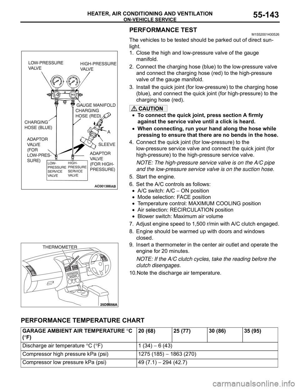
1. Close the high and low-pressure valve of the gauge
manifold.
2. Connect the charging hose (blue) to the low-pressure valve
and connect the charging hose (red) to the high-pressure
valve of the gauge manifold.
3. Install the quick joint (for low-pressure) to the charging hose
(blue), and connect the quick joint (for high-pressure) to the
charging hose (red).
To connect the quick joint, press section A firmly
against the service valve until a click is heard.
When connecting, run your hand along the hose while
pressing to ensure that there are no bends in the hose.
4. Connect the quick joint (for low-pressure) to the
low-pressure service valve and connect the quick joint (for
high-pressure) to the high-pressure service valve.
NOTE: The high-pressure service valve is on the A/C pipe
and the low-pressure service valve is on the suction hose.
5. Start the engine.
6. Set the A/C controls as follows:
A/C switch: A/C ON position
Mode selection: FACE position
Temperature control: MAXIMUM COOLING position
Air selection: RECIRCULATION position
Blower switch: Maximum air volume
7. Adjust engine speed to 1,500 r/min with A/C clutch engaged.
8. Engine should be warmed up with doors and windows
closed.
9. Insert a thermometer in the center air outlet and operate the
engine for 20 minutes.
NOTE: If the A/C clutch cycles, take the reading before the
clutch disengages.
10.Note the discharge air temperature.
PERFORMANCE TEMPERATURE CHART
GARAGE AMBIENT AIR TEMPERATURE C
(
F)20 (68) 25 (77) 30 (86) 35 (95)
Discharge air temperature
C (F) 1 (34) 6 (43)
Compressor high pressure kPa (psi) 1275 (185)
1863 (270)
Compressor low pressure kPa (psi) 49 (7.1)
294 (42.7)
Page 1155 of 1500

SPECIFICATIONS
BODY42-88
COMPONENT IDENTIFICATIONSM1421005400246
LH Front door P4FL
Rear door P4RL
RH Front door P4FR
Rear door P4RR
APPLICABLE SIDE IDENTIFICATION CLIP COLOR
LH Front door Pink
Rear door Yellow
RH Front door Turquoise
Rear door Blue
Page 1218 of 1500
PARKING BRAKE LINING AND DRUM
PARKING BRAKES36-11
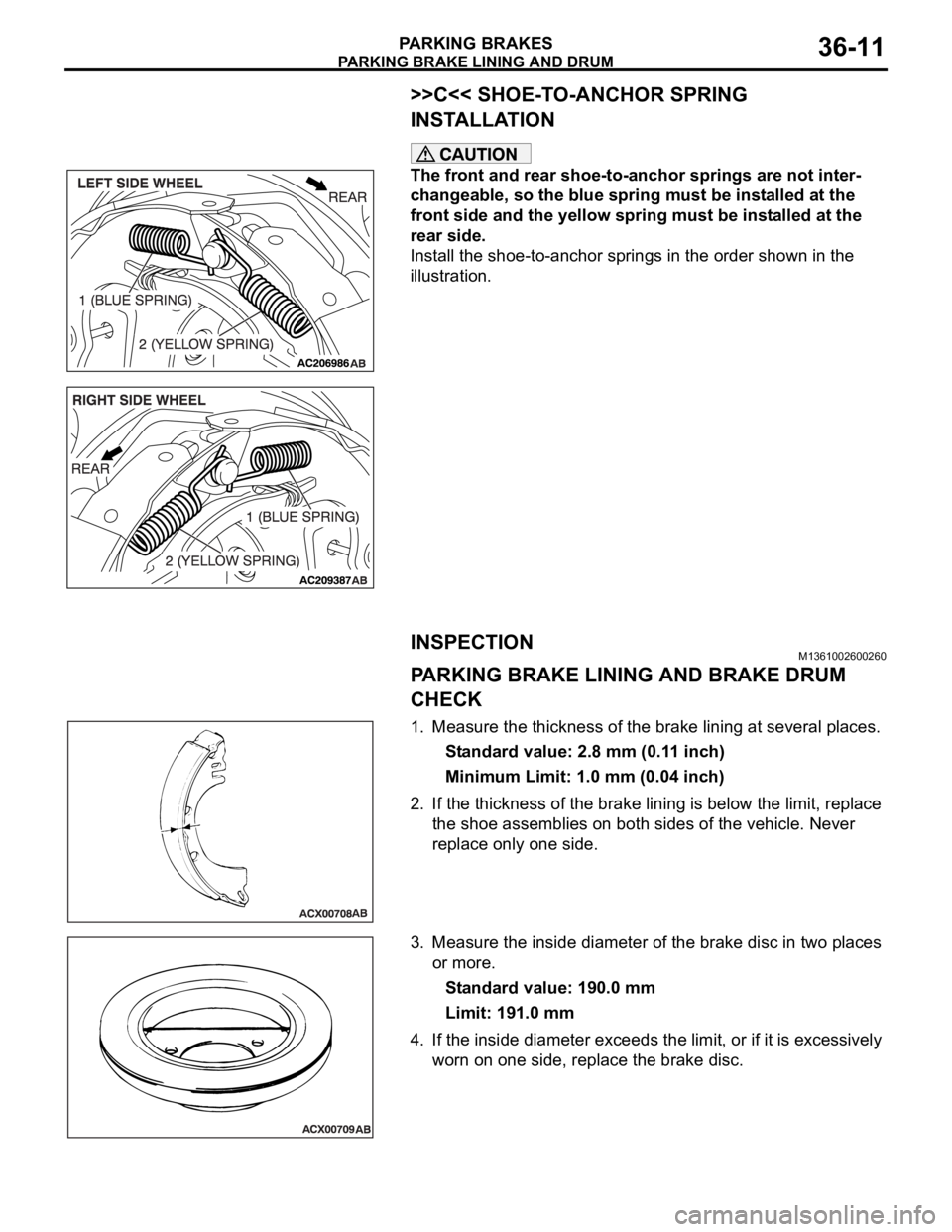
>>C<< SHOE-TO-ANCHOR SPRING
INSTALLATION
The front and rear shoe-to-anchor springs are not inter-
changeable, so the blue spring must be installed at the
front side and the yellow spring must be installed at the
rear side.
Install the shoe-to-anchor springs in the order shown in the
illustration.
INSPECTIONM1361002600260
PARKING BRAKE LINING AND BRAKE DRUM
CHECK
1. Measure the thickness of the brake lining at several places.
Standard value: 2.8 mm (0.11 inch)
Minimum Limit: 1.0 mm (0.04 inch)
2. If the thickness of the brake lining is below the limit, replace
the shoe assemblies on both sides of the vehicle. Never
replace only one side.
3. Measure the inside diameter of the brake disc in two places
or more.
Standard value: 190.0 mm
Limit: 191.0 mm
4. If the inside diameter exceeds the limit, or if it is excessively
worn on one side, replace the brake disc.