fuse MITSUBISHI 380 2005 User Guide
[x] Cancel search | Manufacturer: MITSUBISHI, Model Year: 2005, Model line: 380, Model: MITSUBISHI 380 2005Pages: 1500, PDF Size: 47.87 MB
Page 881 of 1500
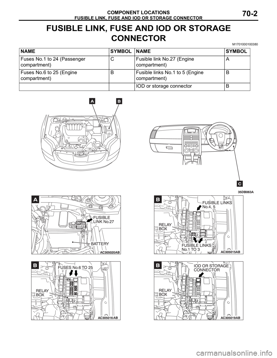
FUSIBLE LINK, FUSE AND IOD OR STORAGE CONNECTOR
COMPONENT LOCATIONS70-2
FUSIBLE LINK, FUSE AND IOD OR STORAGE
CONNECTOR
M1701000100380
NAME SYMBOL NAME SYMBOL
Fuses No.1 to 24 (Passenger
compartment)C Fusible link No.27 (Engine
compartment)A
Fuses No.6 to 25 (Engine
compartment)B Fusible links No.1 to 5 (Engine
compartment)B
IOD or storage connector B
Page 902 of 1500
00E-1
GROUP 00E
GENERAL
CONTENTS
HARNESS CONNECTOR
INSPECTION . . . . . . . . . . . . . . . . . . .00E-2
HOW TO DIAGNOSE . . . . . . . . . . . . .00E-2
HOW TO DIAGNOSE . . . . . . . . . . . . . . . . . 00E-2
TROUBLESHOOTING STEPS . . . . . . . . . . 00E-3
INFORMATION FOR DIAGNOSIS . . . . . . . 00E-3
INSPECTION . . . . . . . . . . . . . . . . . . . . . . . 00E-4INSPECTION INSTRUMENTS . . . . . . . . . . 00E-5
CHECKING FUSES . . . . . . . . . . . . . . . . . . . 00E-6
CHECKING SWITCHES . . . . . . . . . . . . . . . 00E-7
CHECKING RELAYS . . . . . . . . . . . . . . . . . 00E-8
CABLES AND WIRES CHECK . . . . . . . . . . 00E-9
BATTERY HANDLING . . . . . . . . . . . . . . . . 00E-9
GENERAL ELECTRICAL SYSTEM CHECK00E-9
Page 905 of 1500
HOW TO DIAGNOSE
GENERAL
INSPECTIONM1001004600139
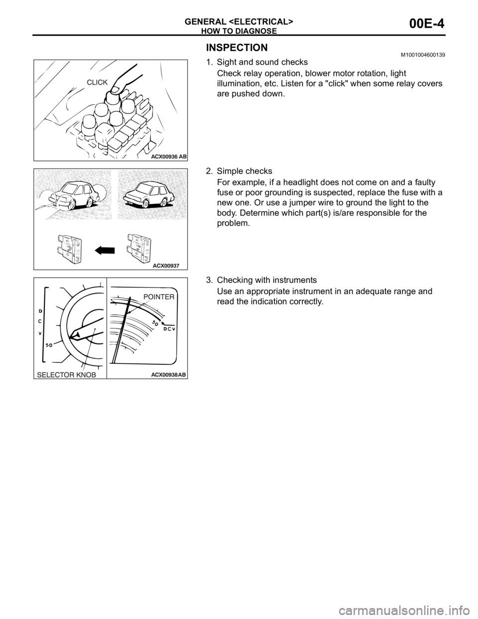
1. Sight and sound checks
Check relay operation, blower motor rotation, light
illumination, etc. Listen for a "click" when some relay covers
are pushed down.
2. Simple checks
For example, if a headlight does not come on and a faulty
fuse or poor grounding is suspected, replace the fuse with a
new one. Or use a jumper wire to ground the light to the
body. Determine which part(s) is/are responsible for the
problem.
3. Checking with instruments
Use an appropriate instrument in an adequate range and
read the indication correctly.
Page 907 of 1500
HOW TO DIAGNOSE
GENERAL
5. Ohmmeter
An ohmmeter is used to check continuity or measure
resistance of a switch or coil. If the measuring range has
been changed, the zero point must be adjusted before
measurement.
CHECKING FUSESM1001005000044
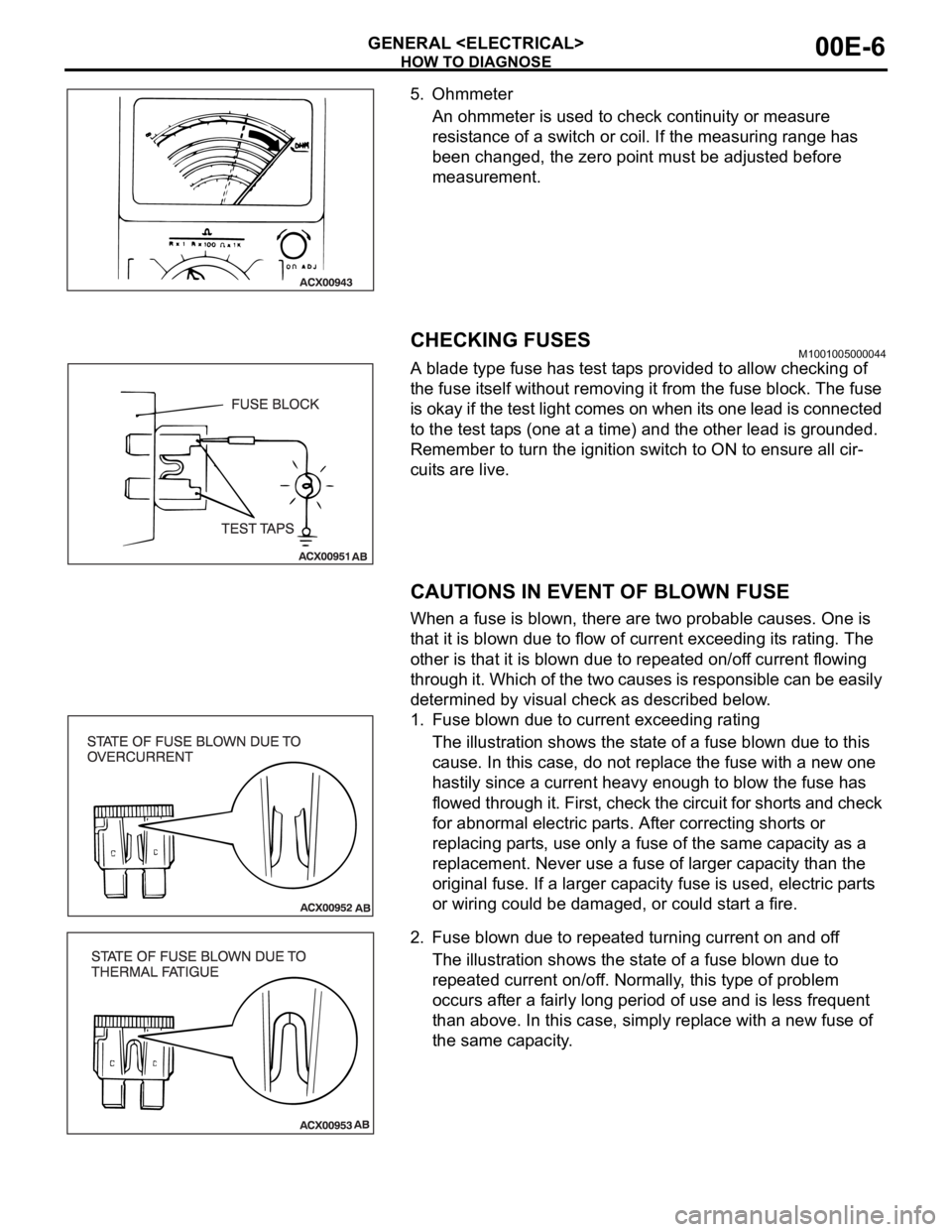
A blade type fuse has test taps provided to allow checking of
the fuse itself without removing it from the fuse block. The fuse
is okay if the test light comes on when its one lead is connected
to the test taps (one at a time) and the other lead is grounded.
Remember to turn the ignition switch to ON to ensure all cir-
cuits are live.
CAUTIONS IN EVENT OF BLOWN FUSE
When a fuse is blown, there are two probable causes. One is
that it is blown due to flow of current exceeding its rating. The
other is that it is blown due to repeated on/off current flowing
through it. Which of the two causes is responsible can be easily
determined by visual check as described below.
1. Fuse blown due to current exceeding rating
The illustration shows the state of a fuse blown due to this
cause. In this case, do not replace the fuse with a new one
hastily since a current heavy enough to blow the fuse has
flowed through it. First, check the circuit for shorts and check
for abnormal electric parts. After correcting shorts or
replacing parts, use only a fuse of the same capacity as a
replacement. Never use a fuse of larger capacity than the
original fuse. If a larger capacity fuse is used, electric parts
or wiring could be damaged, or could start a fire.
2. Fuse blown due to repeated turning current on and off
The illustration shows the state of a fuse blown due to
repeated current on/off. Normally, this type of problem
occurs after a fairly long period of use and is less frequent
than above. In this case, simply replace with a new fuse of
the same capacity.
Page 911 of 1500
HOW TO DIAGNOSE
GENERAL
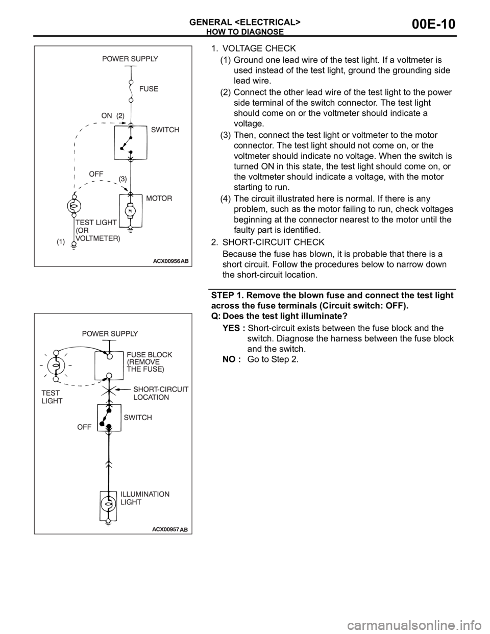
1. VOLTAGE CHECK
(1) Ground one lead wire of the test light. If a voltmeter is
used instead of the test light, ground the grounding side
lead wire.
(2) Connect the other lead wire of the test light to the power
side terminal of the switch connector. The test light
should come on or the voltmeter should indicate a
voltage.
(3) Then, connect the test light or voltmeter to the motor
connector. The test light should not come on, or the
voltmeter should indicate no voltage. When the switch is
turned ON in this state, the test light should come on, or
the voltmeter should indicate a voltage, with the motor
starting to run.
(4) The circuit illustrated here is normal. If there is any
problem, such as the motor failing to run, check voltages
beginning at the connector nearest to the motor until the
faulty part is identified.
2. SHORT-CIRCUIT CHECK
Because the fuse has blown, it is probable that there is a
short circuit. Follow the procedures below to narrow down
the short-circuit location.
STEP 1. Remove the blown fuse and connect the test light
across the fuse terminals (Circuit switch: OFF).
Q: Does the test light illuminate?
YES : Short-circuit exists between the fuse block and the
switch. Diagnose the harness between the fuse block
and the switch.
NO : Go to Step 2.
Page 989 of 1500
CHARGING SYSTEM
ENGINE ELECTRICAL16-12
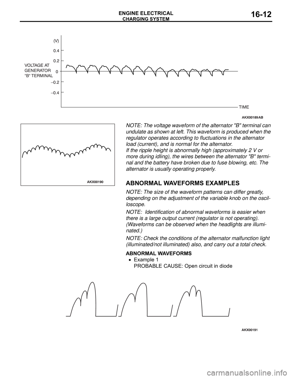
NOTE: The voltage waveform of the alternator "B" terminal can
undulate as shown at left. This waveform is produced when the
regulator operates according to fluctuations in the alternator
load (current), and is normal for the alternator.
If the ripple height is abnormally high (approximately 2 V or
more during idling), the wires between the alternator "B" termi-
nal and the battery have broken due to fuse blowing, etc. The
alternator is usually operating properly.
.
ABNORMAL WAVEFORMS EXAMPLES
NOTE: The size of the waveform patterns can differ greatly,
depending on the adjustment of the variable knob on the oscil-
loscope.
NOTE: Identification of abnormal waveforms is easier when
there is a large output current (regulator is not operating).
(Waveforms can be observed when the headlights are illumi-
nated.)
NOTE: Check the conditions of the alternator malfunction light
(illuminated/not illuminated) also, and carry out a total check.
ABNORMAL WAVEFORMS
Example 1
PROBABLE CAUSE: Open circuit in diode
Page 1100 of 1500
DOOR
BODY42-33
POWER WINDOW OPERATING CURRENT CHECKM1429001100195
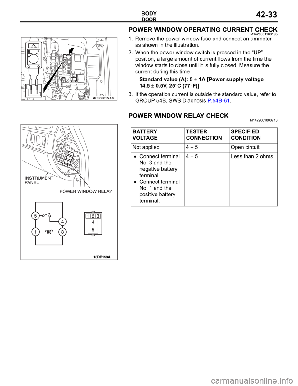
1. Remove the power window fuse and connect an ammeter
as shown in the illustration.
2. When the power window switch is pressed in the “UP”
position, a large amount of current flows from the time the
window starts to close until it is fully closed, Measure the
current during this time
Standard value (A): 5
1A [Power supply voltage
14.5
0.5V, 25C (77F)]
3. If the operation current is outside the standard value, refer to
GROUP 54B, SWS Diagnosis P.54B-61.
POWER WINDOW RELAY CHECKM1429001800213
BATTERY
VOLTAGETESTER
CONNECTIONSPECIFIED
CONDITION
Not applied 4
5 Open circuit
Connect terminal
No. 3 and the
negative battery
terminal.
Connect terminal
No. 1 and the
positive battery
terminal.4
5 Less than 2 ohms
Page 1143 of 1500
SUNROOF ASSEMBLY
BODY42-76
SUNROOF TIMER FUNCTION CHECKM1426004300100
Keep the door closed, turn OFF the ignition switch and check to
see if the sunroof can be operated for 30 seconds after that. If
not, perform troubleshooting (Refer to GROUP 54B, SWS
Diagnosis P.54B-57).
SUNROOF FIT ADJUSTMENTM1426001000285
1. Fully close the roof lid glass.
2. Fully open the sunshade.
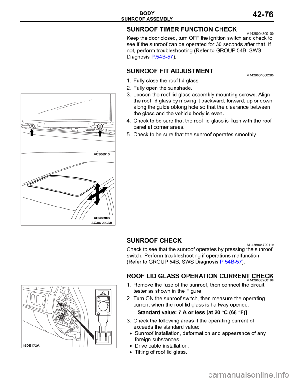
3. Loosen the roof lid glass assembly mounting screws. Align
the roof lid glass by moving it backward, forward, up or down
along the guide oblong hole so that the clearance between
the glass and the vehicle body is even.
4. Check to be sure that the roof lid glass is flush with the roof
panel at corner areas.
5. Check to be sure that the sunroof operates smoothly.
SUNROOF CHECKM1426004700119
Check to see that the sunroof operates by pressing the sunroof
switch. Perform troubleshooting if operations malfunction
(Refer to GROUP 54B, SWS Diagnosis P.54B-57).
ROOF LID GLASS OPERATION CURRENT CHECKM1426003200166
1. Remove the fuse of the sunroof, then connect the circuit
tester as shown in the Figure.
2. Turn ON the sunroof switch, then measure the operating
current when the roof lid glass is halfway opened.
Standard value: 7 A or less [at 20
C (68 F)]
3. Check the following areas if the operating current of
exceeds the standard value:
Sunroof installation, deformation and appearance of any
foreign substances.
Drive cable installation.
Tilting of roof lid glass.
Page 1222 of 1500
00-1
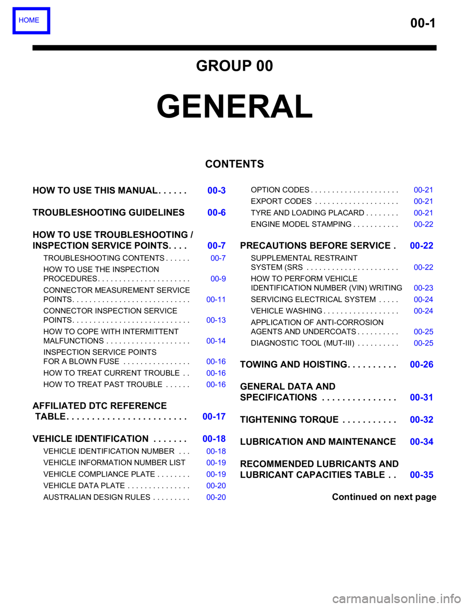
GROUP 00
GENERAL
CONTENTS
HOW TO USE THIS MANUAL . . . . . .00-3
TROUBLESHOOTING GUIDELINES00-6
HOW TO USE TROUBLESHOOTING /
INSPECTION SERVICE POINTS. . . .00-7
TROUBLESHOOTING CONTENTS . . . . . . 00-7
HOW TO USE THE INSPECTION
PROCEDURES . . . . . . . . . . . . . . . . . . . . . . 00-9
CONNECTOR MEASUREMENT SERVICE
POINTS . . . . . . . . . . . . . . . . . . . . . . . . . . . . 00-11
CONNECTOR INSPECTION SERVICE
POINTS . . . . . . . . . . . . . . . . . . . . . . . . . . . . 00-13
HOW TO COPE WITH INTERMITTENT
MALFUNCTIONS . . . . . . . . . . . . . . . . . . . . 00-14
INSPECTION SERVICE POINTS
FOR A BLOWN FUSE . . . . . . . . . . . . . . . . 00-16
HOW TO TREAT CURRENT TROUBLE . . 00-16
HOW TO TREAT PAST TROUBLE . . . . . . 00-16
AFFILIATED DTC REFERENCE
TABLE . . . . . . . . . . . . . . . . . . . . . . . .00-17
VEHICLE IDENTIFICATION . . . . . . .00-18
VEHICLE IDENTIFICATION NUMBER . . . 00-18
VEHICLE INFORMATION NUMBER LIST 00-19
VEHICLE COMPLIANCE PLATE . . . . . . . . 00-19
VEHICLE DATA PLATE . . . . . . . . . . . . . . . 00-20
AUSTRALIAN DESIGN RULES . . . . . . . . . 00-20OPTION CODES . . . . . . . . . . . . . . . . . . . . . 00-21
EXPORT CODES . . . . . . . . . . . . . . . . . . . . 00-21
TYRE AND LOADING PLACARD . . . . . . . . 00-21
ENGINE MODEL STAMPING . . . . . . . . . . . 00-22
PRECAUTIONS BEFORE SERVICE .00-22
SUPPLEMENTAL RESTRAINT
SYSTEM (SRS . . . . . . . . . . . . . . . . . . . . . . 00-22
HOW TO PERFORM VEHICLE
IDENTIFICATION NUMBER (VIN) WRITING00-23
SERVICING ELECTRICAL SYSTEM . . . . . 00-24
VEHICLE WASHING . . . . . . . . . . . . . . . . . . 00-24
APPLICATION OF ANTI-CORROSION
AGENTS AND UNDERCOATS . . . . . . . . . . 00-25
DIAGNOSTIC TOOL (MUT-III) . . . . . . . . . . 00-25
TOWING AND HOISTING. . . . . . . . . .00-26
GENERAL DATA AND
SPECIFICATIONS . . . . . . . . . . . . . . .00-31
TIGHTENING TORQUE . . . . . . . . . . .00-32
LUBRICATION AND MAINTENANCE 00-34
RECOMMENDED LUBRICANTS AND
LUBRICANT CAPACITIES TABLE . .00-35
Continued on next page
Page 1231 of 1500
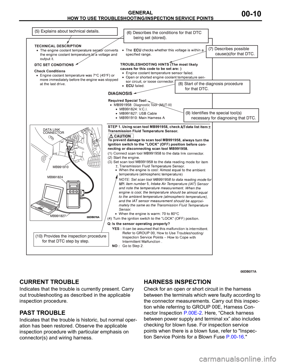
HOW TO USE TROUBLESHOOTING/INSPECTION SERVICE POINTS
GENERAL00-10
CURRENT TROUBLE
Indicates that the trouble is currently present. Carry
out troubleshooting as described in the applicable
inspection procedure.
PAST TROUBLE
Indicates that the trouble is historic, but normal oper-
ation has been restored. Observe the applicable
inspection procedure with particular emphasis on
connector(s) and wiring harness.
HARNESS INSPECTION
Check for an open or short circuit in the harness
between the terminals which were faulty according to
the connector measurements. Carry out this inspec-
tion while referring to GROUP 00E, Harness Con-
nector Inspection P.00E-2. Here, “Check harness
between power supply and terminal xx” also includes
checking for blown fuse. For inspection service
points when there is a blown fuse, refer to "Inspec-
tion Service Points for a Blown Fuse P.00-16."