ESP MITSUBISHI 380 2005 Owner's Manual
[x] Cancel search | Manufacturer: MITSUBISHI, Model Year: 2005, Model line: 380, Model: MITSUBISHI 380 2005Pages: 1500, PDF Size: 47.87 MB
Page 883 of 1500
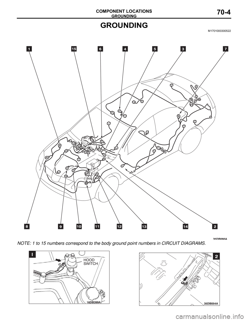
GROUNDING
COMPONENT LOCATIONS70-4
GROUNDINGM1701000300522
NOTE: 1 to 15 numbers correspond to the body ground point numbers in CIRCUIT DIAGRAMS.
Page 905 of 1500
HOW TO DIAGNOSE
GENERAL
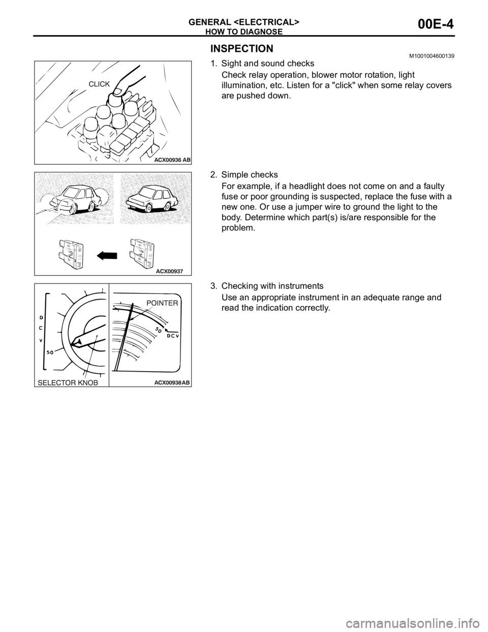
INSPECTIONM1001004600139
1. Sight and sound checks
Check relay operation, blower motor rotation, light
illumination, etc. Listen for a "click" when some relay covers
are pushed down.
2. Simple checks
For example, if a headlight does not come on and a faulty
fuse or poor grounding is suspected, replace the fuse with a
new one. Or use a jumper wire to ground the light to the
body. Determine which part(s) is/are responsible for the
problem.
3. Checking with instruments
Use an appropriate instrument in an adequate range and
read the indication correctly.
Page 907 of 1500
HOW TO DIAGNOSE
GENERAL
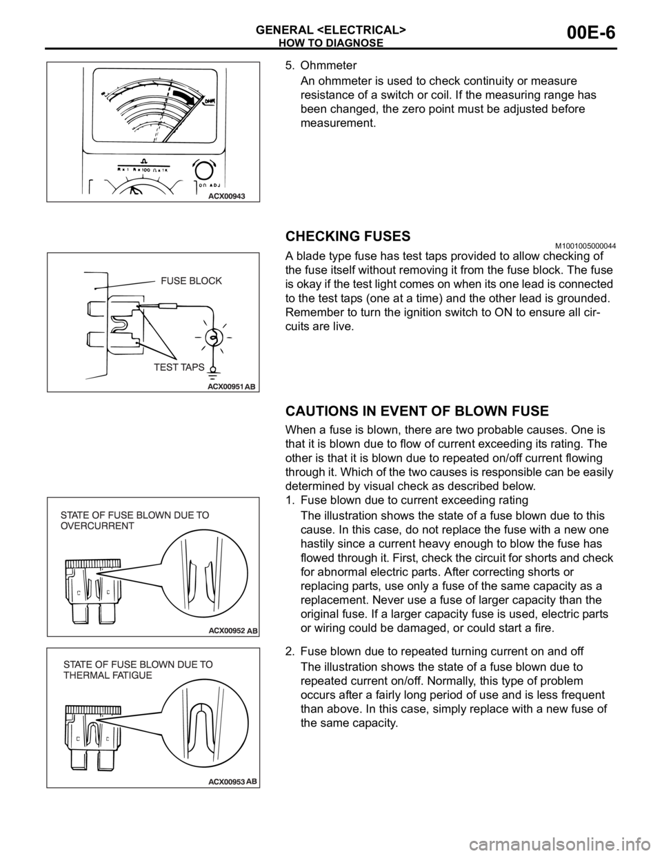
5. Ohmmeter
An ohmmeter is used to check continuity or measure
resistance of a switch or coil. If the measuring range has
been changed, the zero point must be adjusted before
measurement.
CHECKING FUSESM1001005000044
A blade type fuse has test taps provided to allow checking of
the fuse itself without removing it from the fuse block. The fuse
is okay if the test light comes on when its one lead is connected
to the test taps (one at a time) and the other lead is grounded.
Remember to turn the ignition switch to ON to ensure all cir-
cuits are live.
CAUTIONS IN EVENT OF BLOWN FUSE
When a fuse is blown, there are two probable causes. One is
that it is blown due to flow of current exceeding its rating. The
other is that it is blown due to repeated on/off current flowing
through it. Which of the two causes is responsible can be easily
determined by visual check as described below.
1. Fuse blown due to current exceeding rating
The illustration shows the state of a fuse blown due to this
cause. In this case, do not replace the fuse with a new one
hastily since a current heavy enough to blow the fuse has
flowed through it. First, check the circuit for shorts and check
for abnormal electric parts. After correcting shorts or
replacing parts, use only a fuse of the same capacity as a
replacement. Never use a fuse of larger capacity than the
original fuse. If a larger capacity fuse is used, electric parts
or wiring could be damaged, or could start a fire.
2. Fuse blown due to repeated turning current on and off
The illustration shows the state of a fuse blown due to
repeated current on/off. Normally, this type of problem
occurs after a fairly long period of use and is less frequent
than above. In this case, simply replace with a new fuse of
the same capacity.
Page 1007 of 1500
IGNITION SYSTEM
ENGINE ELECTRICAL16-30
IGNITION SYSTEM
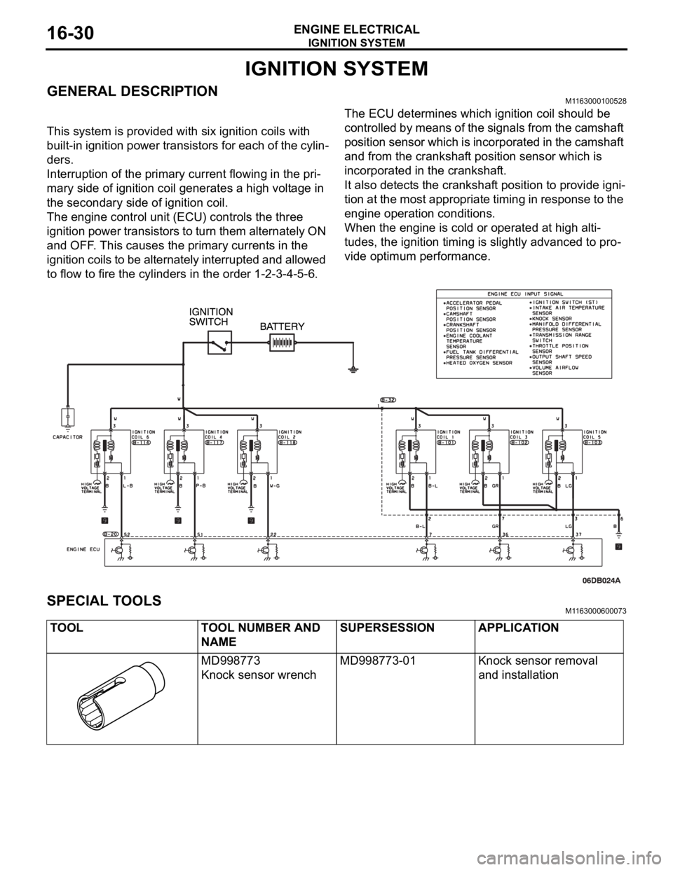
GENERAL DESCRIPTIONM1163000100528
This system is provided with six ignition coils with
built-in ignition power transistors for each of the cylin-
ders.
Interruption of the primary current flowing in the pri-
mary side of ignition coil generates a high voltage in
the secondary side of ignition coil.
The engine control unit (ECU) controls the three
ignition power transistors to turn them alternately ON
and OFF. This causes the primary currents in the
ignition coils to be alternately interrupted and allowed
to flow to fire the cylinders in the order 1-2-3-4-5-6.The ECU determines which ignition coil should be
controlled by means of the signals from the camshaft
position sensor which is incorporated in the camshaft
and from the crankshaft position sensor which is
incorporated in the crankshaft.
It also detects the crankshaft position to provide igni-
tion at the most appropriate timing in response to the
engine operation conditions.
When the engine is cold or operated at high alti-
tudes, the ignition timing is slightly advanced to pro-
vide optimum performance.
SPECIAL TOOLSM1163000600073
TOOL TOOL NUMBER AND
NAMESUPERSESSION APPLICATION
MD998773
Knock sensor wrenchMD998773-01 Knock sensor removal
and installation
Page 1019 of 1500
GENERAL DESCRIPTION
POWER PLANT MOUNT32-2
GENERAL DESCRIPTIONM1321000100373
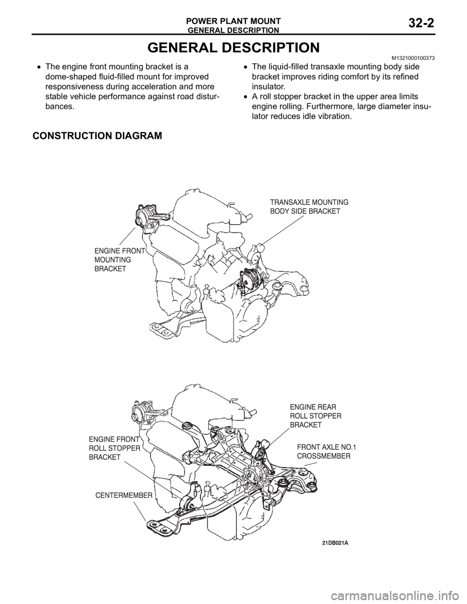
The engine front mounting bracket is a
dome-shaped fluid-filled mount for improved
responsiveness during acceleration and more
stable vehicle performance against road distur-
bances.The liquid-filled transaxle mounting body side
bracket improves riding comfort by its refined
insulator.
A roll stopper bracket in the upper area limits
engine rolling. Furthermore, large diameter insu-
lator reduces idle vibration.
CONSTRUCTION DIAGRAM
Page 1138 of 1500

KEYLESS ENTRY SYSTEM
BODY42-71
KEYLESS ENTRY SYSTEM INSPECTIONBGBHCDAE
Check the following items. If defective, refer to GROUP 54B,
SWS Diagnosis P.54B-10).
1. Operate the transmitter to check that the doors can be
locked and unlocked.
NOTE: The adjustment function allows you to change the
unlock operation setting as follows. Prior to that check, con-
firm which setting is activated.
.
a. When the unlock button is pressed once, the driver's
door will be unlocked. Then when the button is pressed
once again, all the doors will be opened (initial setting).
b. When the unlock button is pressed only once, all the
doors will be opened.
2. Press the trunk lid button of transmitter twice (press once,
and then press again within 5 seconds) and confirm that the
trunk lid opens.
3. Operate the transmitter to check that the answerback
function works in response to doors locking/unlocking.
NOTE: The adjustment function allows you to change the
hazard answerback setting as follows. Prior to that check,
confirm which setting is activated.
.
a. Turn-signal lights: Flash once when doors are locked,
and twice when unlocked (initial setting)
b. Turn-signal lights: Flash once when doors are locked,
but does not flash when unlocked.
c. Turn-signal lights: Do not flash when doors are locked,
but flash twice when unlocked.
d. Turn-signal lights: Do not flash when doors are locked
and unlocked.
NOTE: The adjustment function allows you to change the
horn answerback setting as follows. Prior to that check, con-
firm which setting is activated.
.
a. Horn: Sounds once when the lock button is pressed.
b. Horn: Sounds once when the lock button is pressed (ini-
tial setting).
c. Horn: Does not sound.
KEYLESS ENTRY SYSTEM TIMER LOCK
FUNCTION INSPECTION
BGBEBDIA
If the doors are not locked within 30 seconds after the unlock
button is pressed, refer to GROUP 54B, SWS Diagnosis
P.54B-10.
NOTE: If either of the doors is opened or the key is inserted in
the ignition switch within that 30-second period, the timer lock
function will be cancelled.
Page 1228 of 1500
HOW TO USE TROUBLESHOOTING/INSPECTION SERVICE POINTS
GENERAL00-7
HOW TO USE TROUBLESHOOTING/INSPECTION SERVICE
POINTS
TROUBLESHOOTING CONTENTSM1001013300062
During diagnosis, a DTC code associated with
other system may be set when the ignition
switch is turned on with connector(s) discon-
nected. On completion, confirm all systems
for DTC code(s). If DTC code(s) are set, erase
them all.
When the DIAGNOSTIC TOOL (MUT-III)
detects a diagnostic trouble code, its display
informs users whether a mechanical problem
currently exists (“current trouble”) or whether
it existed before but normal operation has
been restored (“past trouble”). However, if an
MPI, TPMS or SRS airbag-related DTC is set,
“Active DTC/Stored DTC” is not displayed. In
this case, follow the diagnosis procedure for
current trouble.
If a trouble, detected in a CAN communica-
tion-capable system, can be reproduced,
diagnose the CAN bus lines (Refer to GROUP
54C, Can Bus Line Diagnostics Chart
P.54C-15 or P.54C-15).
Troubleshooting of electronic control systems for
which the MUT -III can be used follows the basic out-
line described below. Even in systems for which the
MUT-III cannot be used, part of these systems still
follow this outline.
1. STANDARD FLOW OF DIAGNOSTIC
TROUBLESHOOTING
Troubleshooting strategy is shown in each group.
2. SYSTEM OPERATION AND SYMPTOM
VERIFICATION TESTS
If verification of the symptom(s) is difficult, proce-
dures for checking operation and verifying symptoms
are shown.
3. DIAGNOSTIC FUNCTION
The following trouble code diagnoses are shown.
How to read diagnostic trouble codes
How to erase diagnostic trouble codes
Input inspection service points
4. DIAGNOSTIC TROUBLE CODE CHART
If the MUT-III displays a diagnostic trouble code, find
the applicable inspection procedure according to this
chart.
5. SYMPTOM CHART
If there are symptoms, even though the MUT-III
shows that no DTCs are set, inspection procedures
for each symptom will be found by using this chart.
6. DIAGNOSTIC TROUBLE CODE
PROCEDURES
Indicates the inspection procedures corresponding to
each diagnostic trouble code. (Refer to P.00-9).
7. SYMPTOM PROCEDURES
Indicates the inspection procedures corresponding to
each symptom listed in the Symptom Chart (Refer to
P.00-9).
8. SERVICE DATA REFERENCE TABLE
Inspection items and normal judgment values have
been provided in this chart as reference information.
9. CHECK AT ECU TERMINALS
Terminal numbers for the ECU connectors, inspec-
tion items, and standard values have been provided
in this chart as reference information.
.
TERMINAL VOLTAGE CHECKS
1. Use correct tool to check each pin location on the
ENGINE-ECU Check harnes MB992044 and
measure with voltmeter.
Short-circuiting the positive (+) test probe
between a connector terminal and ground could
damage the vehicle wiring, the sensor, the ECU,
or all three. Use care to prevent this!
2. Insert the correct terminal tool into each of the
ENGINE-ECU check harness connector
terminals, and measure the voltage while referring
to the check chart.
NOTE: Measure voltage with the ECU connectors
connected.
You may find it convenient to pull out the ECU to
make it easier to connect the ENGINE-ECU check
harness.
Page 1229 of 1500

HOW TO USE TROUBLESHOOTING/INSPECTION SERVICE POINTS
GENERAL00-8
Checks don't have to be carried out in the order
given in the chart.
3. If voltage readings differ from normal condition
values, check related sensors, actuators, and
wiring. Replace or repair as needed.
4. After repair or replacement, recheck with the
voltmeter to confirm that the repair has corrected
the problem.
.
TERMINAL RESISTANCE AND
CONTINUITY CHECKS
1. Turn the ignition switch to the “LOCK” (OFF)
position.
2. Disconnect the ECU connector.
If resistance and continuity checks are per-
formed on the wrong terminals, damage to the
vehicle wiring, sensors, ECU, and/or ohmmeter
may occur. Use care to prevent this!
3. Measure the resistance and check for continuity
between the terminals of the ENGIN-ECU check
harness MB992044 connector while referring to
the check chart.
NOTE: Checks don't have to be carried out in the
order given in the chart.
4. If the ohmmeter shows any deviation from the
Normal Condition value, check the corresponding
sensor, actuator and related electrical wiring, then
repair or replace.
5. After repair or replacement, recheck with the
ohmmeter to confirm that the repair has corrected
the problem.
10. INSPECTION PROCEDURES USING
AN OSCILLOSCOPE
When there are inspection procedures using an
oscilloscope, these are listed.
Page 1235 of 1500
HOW TO USE TROUBLESHOOTING/INSPECTION SERVICE POINTS
GENERAL00-14
CONNECTOR ENGAGEMENT INSPECTION
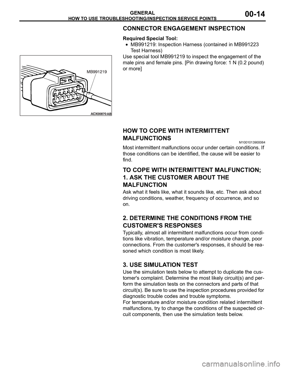
Required Special Tool:
MB991219: Inspection Harness (contained in MB991223
Test Harness)
Use special tool MB991219 to inspect the engagement of the
male pins and female pins. [Pin drawing force: 1 N (0.2 pound)
or more]
HOW TO COPE WITH INTERMITTENT
MALFUNCTIONS
M1001013900064
Most intermittent malfunctions occur under certain conditions. If
those conditions can be identified, the cause will be easier to
find.
.
TO COPE WITH INTERMITTENT MALFUNCTION;
1. ASK THE CUSTOMER ABOUT THE
MALFUNCTION
Ask what it feels like, what it sounds like, etc. Then ask about
driving conditions, weather, frequency of occurrence, and so
on.
.
2. DETERMINE THE CONDITIONS FROM THE
CUSTOMER'S RESPONSES
Typically, almost all intermittent malfunctions occur from condi-
tions like vibration, temperature and/or moisture change, poor
connections. From the customer's responses, it should be rea-
soned which condition is most likely.
.
3. USE SIMULATION TEST
Use the simulation tests below to attempt to duplicate the cus-
tomer's complaint. Determine the most likely circuit(s) and per-
form the simulation tests on the connectors and parts of that
circuit(s). Be sure to use the inspection procedures provided for
diagnostic trouble codes and trouble symptoms.
For temperature and/or moisture condition related intermittent
malfunctions, try to change the conditions of the suspected cir-
cuit components, then use the simulation tests below.
.
Page 1236 of 1500
HOW TO USE TROUBLESHOOTING/INSPECTION SERVICE POINTS
GENERAL00-15
4. VERIFY THE INTERMITTENT MALFUNCTION IS
ELIMINATED
Repair the malfunctioning part and try to duplicate the condi-
tion(s) again to verify the intermittent malfunction has been
eliminated.
.
SIMULATION TESTS
NOTE: In case of difficulty in finding the cause of the intermit-
tent malfunction, the data recorder function in the
DIAGNOSTIC TOOL (MUT-III) is effective.
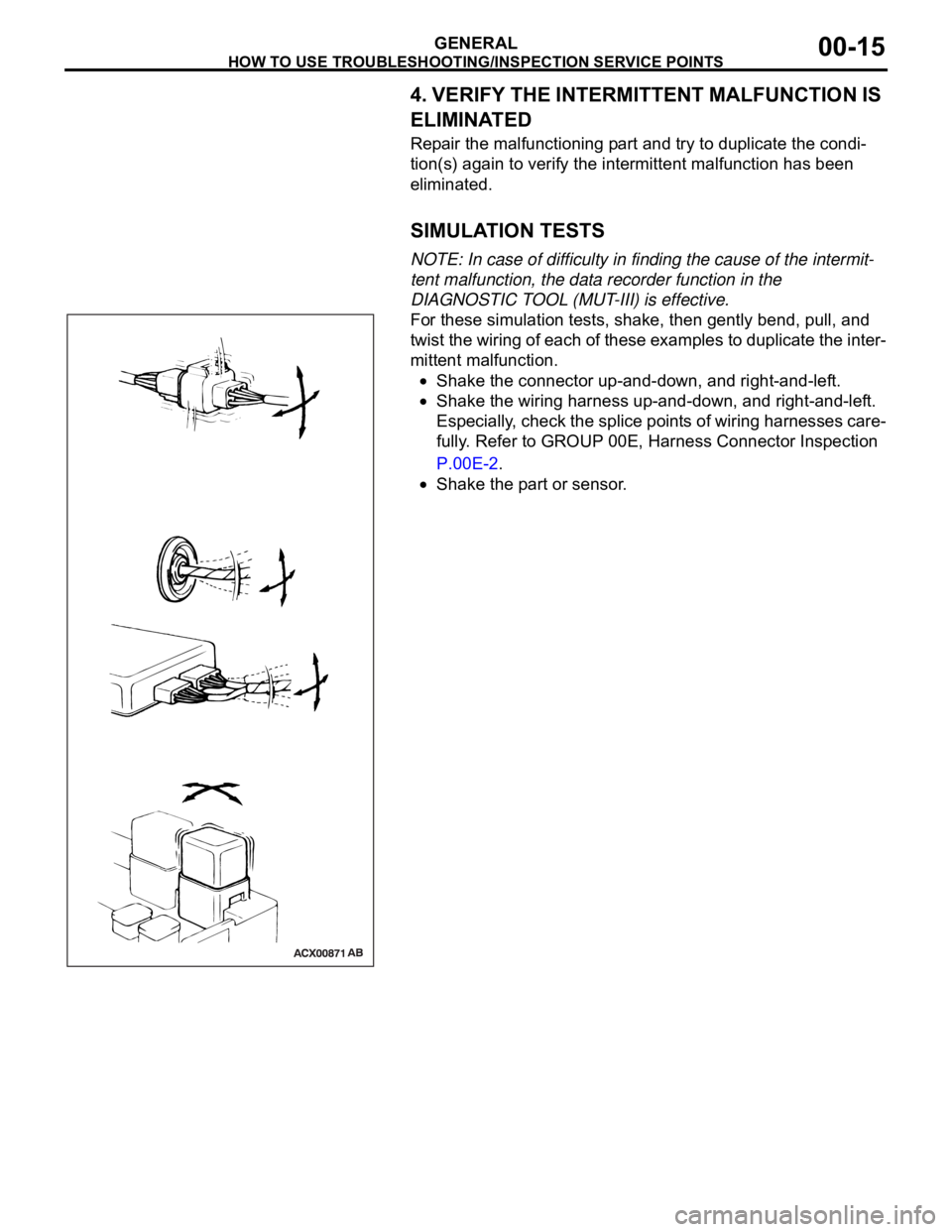
For these simulation tests, shake, then gently bend, pull, and
twist the wiring of each of these examples to duplicate the inter-
mittent malfunction.
Shake the connector up-and-down, and right-and-left.
Shake the wiring harness up-and-down, and right-and-left.
Especially, check the splice points of wiring harnesses care-
fully. Refer to GROUP 00E, Harness Connector Inspection
P.00E-2.
Shake the part or sensor.