ESP MITSUBISHI 380 2005 Service Manual
[x] Cancel search | Manufacturer: MITSUBISHI, Model Year: 2005, Model line: 380, Model: MITSUBISHI 380 2005Pages: 1500, PDF Size: 47.87 MB
Page 1313 of 1500
TRACTION CONTROL SYSTEM (TCL) DIAGNOSIS
TRACTION CONTROL SYSTEM (TCL)13C-34
INSPECTION PROCEDURE 6: TCL does not Operate.
NOTE: If the ABS-8 ECU or the active wheel
speed sensor are disconnected, or if the wiring is
an open/ short circuit, the ABS 8 ECU will shut
off power supply to the respective wheel speed
sensor. All other wheel speed sensors will oper-
ate normally. To restore the power supply, the
ignition switch must be turned to the "OFF" posi-
tion then to the "ON" position again.
.
COMMENT
The fail-safe function is probably cancelling TCL. In
this case, diagnostic tool MB991958 can be used to
retest each system by checking the diagnostic trou-
ble codes.
.
TROUBLESHOOTING HINTS (THE MOST
LIKELY CAUSES FOR THIS CASE:)
Malfunction of the CAN bus line.
Malfunction of the MPI system.
Malfunction of the A/T system.
Malfunction of the ABS/TCL-ECU.
DIAGNOSIS
Required Special Tools:
MB991958: Diagnostic Tool (MUT-III Sub Assembly)
MB991824: V.C.I.
MB991827: MUT-III USB Cable
MB991910: MUT-III Main Harness A
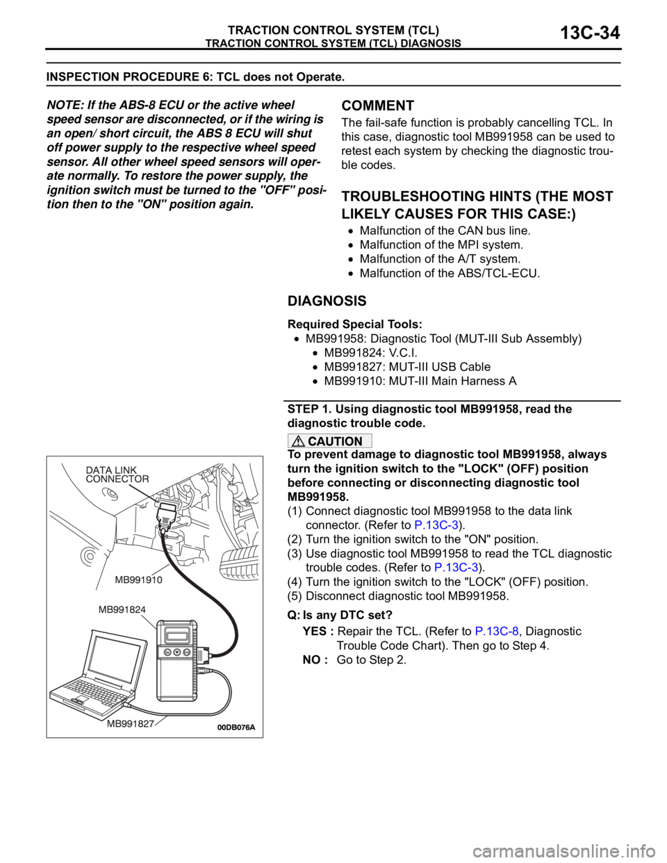
STEP 1. Using diagnostic tool MB991958, read the
diagnostic trouble code.
To prevent damage to diagnostic tool MB991958, always
turn the ignition switch to the "LOCK" (OFF) position
before connecting or disconnecting diagnostic tool
MB991958.
(1) Connect diagnostic tool MB991958 to the data link
connector. (Refer to P.13C-3).
(2) Turn the ignition switch to the "ON" position.
(3) Use diagnostic tool MB991958 to read the TCL diagnostic
trouble codes. (Refer to P.13C-3).
(4) Turn the ignition switch to the "LOCK" (OFF) position.
(5) Disconnect diagnostic tool MB991958.
Q: Is any DTC set?
YES : Repair the TCL. (Refer to P.13C-8, Diagnostic
Trouble Code Chart). Then go to Step 4.
NO : Go to Step 2.
Page 1315 of 1500

TRACTION CONTROL SYSTEM (TCL) DIAGNOSIS
TRACTION CONTROL SYSTEM (TCL)13C-36
DATA LIST REFERENCE TABLEM1136003500071
NOTE: If the ABS-8 ECU or the active wheel
speed sensor are disconnected, or if the wiring is
an open/ short circuit, the ABS 8 ECU will shut
off power supply to the respective wheel speed
sensor. All other wheel speed sensors will oper-
ate normally. To restore the power supply, the
ignition switch must be turned to the "OFF" posi-
tion then to the "ON" position again.The following items can be read by the diagnostic
tool from the ABS/TCL-ECU input data. (Refer to
P.13C-3).
NOTE: Since the TCL is controlled with the same ABS/TCL-ECU used to control the ABS, the stoplight switch
check item (No.6) used only for the ABS also appear.MUT-III
DIAGNOSTI
C TOOL
DISPLAYITEM
NO.CHECK ITEM CHECKING REQUIREMENTS NORMAL
VA L U E
FL wheel
speed sensor01 Front left wheel speed sensor Drive the vehicle Vehicle speeds
displayed on the
speedometer
and diagnostic
tool are identical. FR wheel
speed sensor02 Front right wheel speed sensor
RL wheel
speed sensor03 Rear left wheel speed sensor
RR wheel
speed sensor04 Rear right left wheel speed
sensor
Power supply
voltage05 ABS/TCL-ECU power supply
voltageIgnition switch power supply
voltageBattery positive
voltage
Stoplamp
switch
(input)*06 Stoplamp switch Depress the brake pedal. ON
Release the brake pedal. OFF
Stoplamp
switch*13 Stoplamp switch Depress the brake pedal. ON
Release the brake pedal. OFF
Pump motor 21 Pump motor When the ABS outputs the
operation permission signal
during drivingON
When the ABS outputs the
operation permission signal
during drivingOFF
Valve relay 30 Valve relayWhen the ABS outputs the
operation permission signal
during drivingON
When the ABS outputs the
operation permission signal
during drivingOFF
TCL mode 35 TCL operation When the TCL outputs the
operation permission signal
during drivingON
When the TCL outputs the
operation inhibition signal
during drivingOFF
Page 1316 of 1500

TRACTION CONTROL SYSTEM (TCL) DIAGNOSIS
TRACTION CONTROL SYSTEM (TCL)13C-37
ACTUATOR TEST REFERENCE TABLEM1136003600067
NOTE: If the ABS-8 ECU or the active wheel
speed sensor are disconnected, or if the wiring is
an open/ short circuit, the ABS 8 ECU will shut
off power supply to the respective wheel speed
sensor. All other wheel speed sensors will oper-
ate normally. To restore the power supply, the
ignition switch must be turned to the "OFF" posi-
tion then to the "ON" position again.The diagnostic tool activates the following actuators
for testing. (Refer to P.13C-3).
NOTE: Since the TCL is controlled with the same ABS/TCL-ECU used to control the ABS, the FL, FR, RL or
RR Wheel ABS Drive testing items (No.01 to 04) used only for the ABS also appear. MUT-III
DIAGNOSTIC TOOL
DISPLAYITEM NO. CHECK ITEM PARTS TO BE ACTIVATED
FL wheel ABS Drive* 01 Solenoid valve for front left wheel Solenoid valves and pump
motors in the hydraulic unit
(simple inspection mode) FR wheel ABS Drive* 02 Solenoid valve for front right wheel
RL wheel ABS Drive* 03 Solenoid valve for rear left wheel
RR wheel ABS
Drive*04 Solenoid valve for rear right wheel
Engine TCL Drive 09 TCL operation check Outputs the engine torque
control signal (engine torque =
0) to PCM for three seconds.
Page 1320 of 1500
TRACTION CONTROL SYSTEM (TCL) DIAGNOSIS
TRACTION CONTROL SYSTEM (TCL)13C-41
VOLTAGE AND SIGNAL CHECK AT ABS-ECU
(A-02) USING OSCILLOSCOPE
NOTE: If the ABS-8 ECU or the active wheel speed
sensor are disconnected, or if the wiring is an open/
short circuit, the ABS 8 ECU will shut off power sup-
ply to the respective wheel speed sensor. All other
wheel speed sensors will operate normally. To
restore the power supply, the ignition switch must be
turned to the "OFF" position then to the "ON" position
again..
WHEEL SPEED SENSOR AIR GAP:
Sensor air gap: (0.2mm - 0.85mm).
.
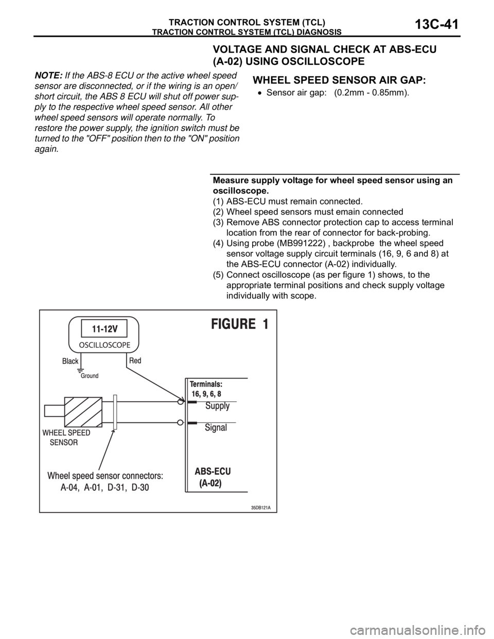
Measure supply voltage for wheel speed sensor using an
oscilloscope.
(1) ABS-ECU must remain connected.
(2) Wheel speed sensors must emain connected
(3) Remove ABS connector protection cap to access terminal
location from the rear of connector for back-probing.
(4) Using probe (MB991222) , backprobe the wheel speed
sensor voltage supply circuit terminals (16, 9, 6 and 8) at
the ABS-ECU connector (A-02) individually.
(5) Connect oscilloscope (as per figure 1) shows, to the
appropriate terminal positions and check supply voltage
individually with scope.
Page 1323 of 1500
TRACTION CONTROL SYSTEM (TCL) DIAGNOSIS
TRACTION CONTROL SYSTEM (TCL)13C-44
Connect oscilloscope to FL sensor signal terminal (5) at
ABS-ECU (A-02)
Connect oscilloscope to FR sensor signal terminal (10)
at ABS-ECU (A-02)
Connect oscilloscope to RL sensor signal terminal (17)
at ABS-ECU (A-02)
Connect oscilloscope to RR sensor signal terminal (19)
at ABS-ECU (A-02)
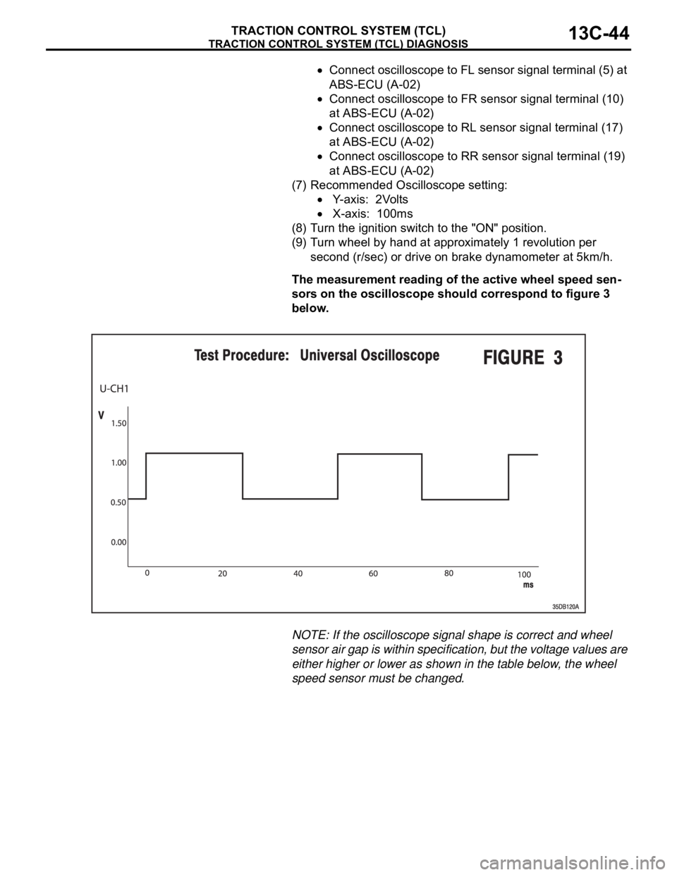
(7) Recommended Oscilloscope setting:
Y-axis: 2Volts
X-axis: 100ms
(8) Turn the ignition switch to the "ON" position.
(9) Turn wheel by hand at approximately 1 revolution per
second (r/sec) or drive on brake dynamometer at 5km/h.
The measurement reading of the active wheel speed sen-
sors on the oscilloscope should correspond to figure 3
below.
NOTE: If the oscilloscope signal shape is correct and wheel
sensor air gap is within specification, but the voltage values are
either higher or lower as shown in the table below, the wheel
speed sensor must be changed.
Page 1327 of 1500
ON-VEHICLE SERVICE
TRACTION CONTROL SYSTEM (TCL)13C-48
To prevent damage to diagnostic tool MB991958, always
turn the ignition switch to the "LOCK" (OFF) position
before connecting or disconnecting diagnostic tool
MB991958.
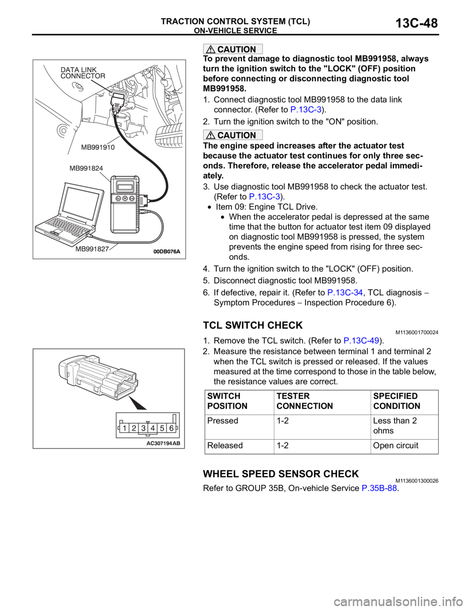
1. Connect diagnostic tool MB991958 to the data link
connector. (Refer to P.13C-3).
2. Turn the ignition switch to the "ON" position.
The engine speed increases after the actuator test
because the actuator test continues for only three sec-
onds. Therefore, release the accelerator pedal immedi-
ately.
3. Use diagnostic tool MB991958 to check the actuator test.
(Refer to P.13C-3).
Item 09: Engine TCL Drive.
When the accelerator pedal is depressed at the same
time that the button for actuator test item 09 displayed
on diagnostic tool MB991958 is pressed, the system
prevents the engine speed from rising for three sec-
onds.
4. Turn the ignition switch to the "LOCK" (OFF) position.
5. Disconnect diagnostic tool MB991958.
6. If defective, repair it. (Refer to P.13C-34, TCL diagnosis
Symptom Procedures
Inspection Procedure 6).
TCL SWITCH CHECKM1136001700024
1. Remove the TCL switch. (Refer to P.13C-49).
2. Measure the resistance between terminal 1 and terminal 2
when the TCL switch is pressed or released. If the values
measured at the time correspond to those in the table below,
the resistance values are correct.
WHEEL SPEED SENSOR CHECKM1136001300026
Refer to GROUP 35B, On-vehicle Service P.35B-88.
SWITCH
POSITIONTESTER
CONNECTIONSPECIFIED
CONDITION
Pressed 1-2 Less than 2
ohms
Released 1-2 Open circuit
Page 1396 of 1500

AUTO-CRUISE CONTROL
ENGINE AND EMISSION CONTROL17-65
DATA LIST REFERENCE TABLE - Auto Cruise ControlM1172002400471
When shifting the selector lever to "D" range, apply the brakes so that the vehicle does not move
forward.
Driving tests always need two persons: one driver and one observer.
NOTE: *:After the inspection is completed, disconnect the throttle position sensor connector, and then delete
the diagnostic trouble code using use of Diagnostic Tool MB991958. (Refer to P.17-11).
MUT-III
Diagnostic
To o l
DISPLAYITEM
NO.INSPECTION ITEM INSPECTION REQUIREMENT NORMAL
CONDITION
APS
SNS(MAIN)11 A c c e l e r a t o r p e d a l
position sensor (main)Ignition
switch:
"ON"Accelerator pedal: Released
435
1,035 mV
Accelerator pedal: Gradually
depressedIncreases in
response to the
pedal depression
stroke
Accelerator pedal: Fully
depressed4,000 mV or more
BRAKE SW 89 Stoplamp switch Brake pedal: Depressed ON
Brake pedal: Released OFF
CANCEL
CODE57 Cancel code Ignition switch: "ON" The cancel code,
which set when the
auto-cruise control
system was
cancelled at the
last time, is set
again.
CANCEL
SWITCH75 Auto-cruise
control
switchCANCEL "CANCEL" switch: ON ON
"CANCEL" switch: OFF OFF
CLUTCH SW 78 Transmission inhibitor
switchTransmission inhibitor switch: "P" or
"N"ON
Transmission inhibitor switch: Other
than aboveOFF
CRUISE 81 Auto-cruise control
system operationAuto-cruise control system: active ON
Auto-cruise control system: Inactive OFF
MAIN SW 86 Auto-cruise
control
switchCRUISE
(MAIN)"CRUISE" (MAIN) switch: "ON" ON
"CRUISE" (MAIN) switch: "OFF" OFF
RESUME
SWITCH91 Auto-cruise
control
switchACC/RES "ACC/RES" switch: ON ON
"ACC/RES" switch: OFF OFF
SET SWITCH 92 Auto-cruise
control
switchCOAST/S
ET"COAST/SET" switch: ON ON
"COAST/SET" switch: OFF OFF
STOPLIGHT
SW74 Stoplamp switch Brake pedal: Depressed ON
Brake pedal: Released OFF
Page 1404 of 1500
AUTO-CRUISE CONTROL
ENGINE AND EMISSION CONTROL17-73
AUTO-CRUISE CONTROL SYSTEM COMPONENT
CHECK
M1172001700316
AUTO-CRUISE CONTROL SWITCH CHECK
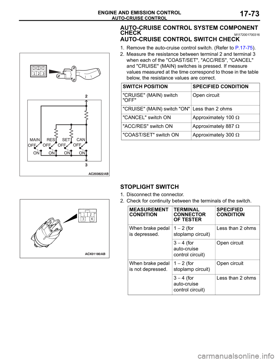
1. Remove the auto-cruise control switch. (Refer to P.17-75).
2. Measure the resistance between terminal 2 and terminal 3
when each of the "COAST/SET", "ACC/RES", "CANCEL"
and "CRUISE" (MAIN) switches is pressed. If measure
values measured at the time correspond to those in the table
below, the resistance values are correct.
STOPLIGHT SWITCH
1. Disconnect the connector.
2. Check for continuity between the terminals of the switch.SWITCH POSITION SPECIFIED CONDITION
"CRUISE" (MAIN) switch
"OFF"Open circuit
"CRUISE" (MAIN) switch "ON" Less than 2 ohms
"CANCEL" switch ON Approximately 100
"ACC/RES" switch ON Approximately 887
"COAST/SET" switch ON Approximately 300
MEASUREMENT
CONDITIONTERMINAL
CONNECTOR
OF TESTERSPECIFIED
CONDITION
When brake pedal
is depressed.1
2 (for
stoplamp circuit)Less than 2 ohms
3
4 (for
auto-cruise
control circuit)Open circuit
When brake pedal
is not depressed.1
2 (for
stoplamp circuit)Open circuit
3
4 (for
auto-cruise
control circuit)Less than 2 ohms
Page 1442 of 1500
DRIVE SHAFT ASSEMBLY
FRONT AXLE26-25
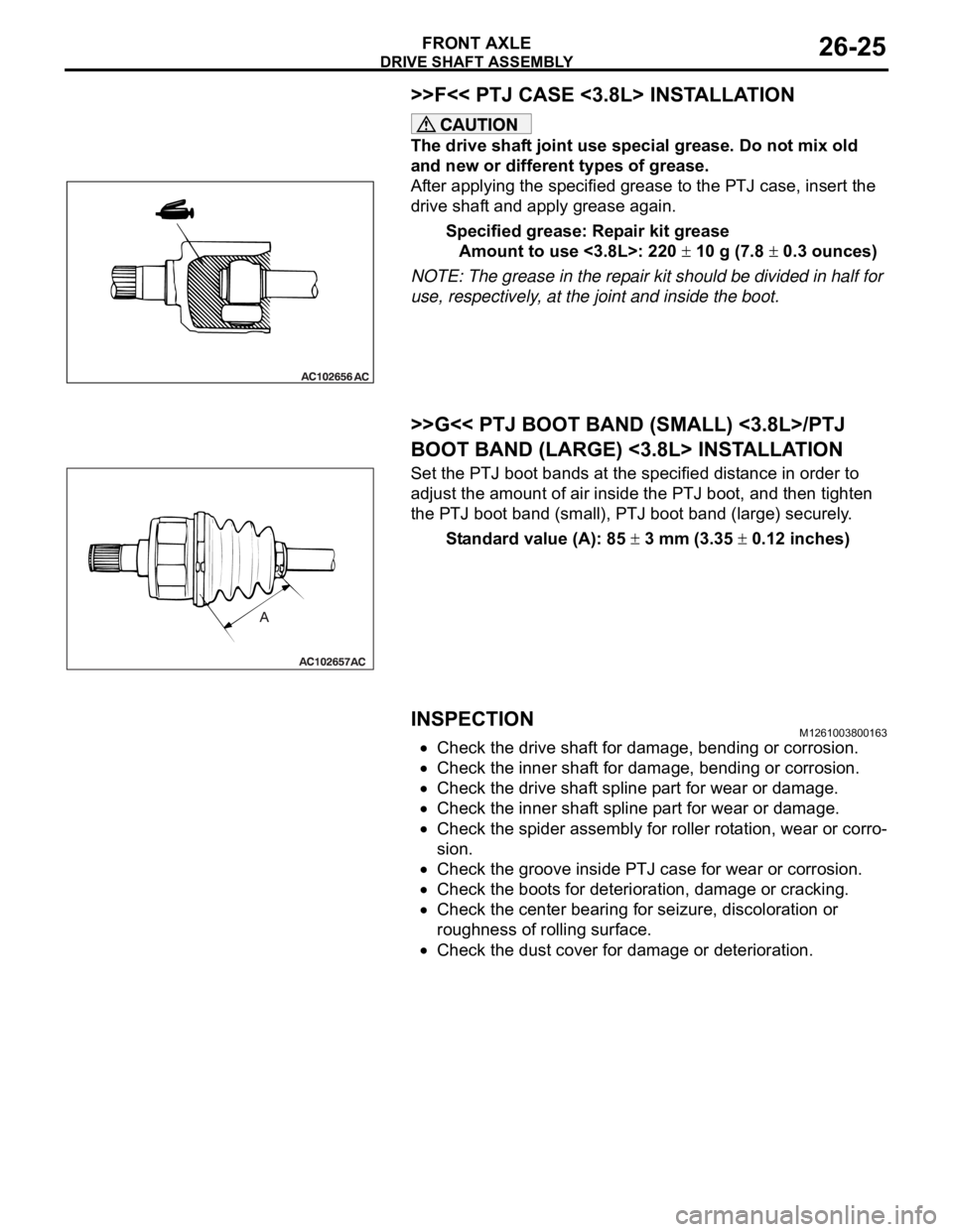
>>F<< PTJ CASE <3.8L> INSTALLATION
The drive shaft joint use special grease. Do not mix old
and new or different types of grease.
After applying the specified grease to the PTJ case, insert the
drive shaft and apply grease again.
Specified grease: Repair kit grease
Amount to use <3.8L>: 220
10 g (7.8 0.3 ounces)
NOTE: The grease in the repair kit should be divided in half for
use, respectively, at the joint and inside the boot.
.
>>G<< PTJ BOOT BAND (SMALL) <3.8L>/PTJ
BOOT BAND (LARGE) <3.8L> INSTALLATION
Set the PTJ boot bands at the specified distance in order to
adjust the amount of air inside the PTJ boot, and then tighten
the PTJ boot band (small), PTJ boot band (large) securely.
Standard value (A): 85
3 mm (3.35 0.12 inches)
INSPECTIONM1261003800163
Check the drive shaft for damage, bending or corrosion.
Check the inner shaft for damage, bending or corrosion.
Check the drive shaft spline part for wear or damage.
Check the inner shaft spline part for wear or damage.
Check the spider assembly for roller rotation, wear or corro-
sion.
Check the groove inside PTJ case for wear or corrosion.
Check the boots for deterioration, damage or cracking.
Check the center bearing for seizure, discoloration or
roughness of rolling surface.
Check the dust cover for damage or deterioration.
Page 1467 of 1500
GENERAL DESCRIPTION
AUTOMATIC TRANSMISSION23A-8
FEATURES
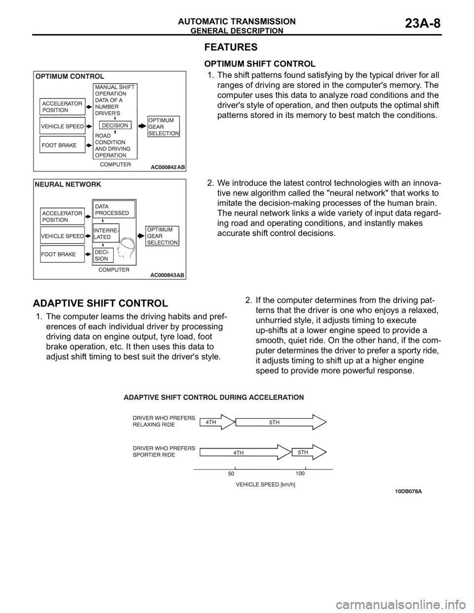
OPTIMUM SHIFT CONTROL
1. The shift patterns found satisfying by the typical driver for all
ranges of driving are stored in the computer's memory. The
computer uses this data to analyze road conditions and the
driver's style of operation, and then outputs the optimal shift
patterns stored in its memory to best match the conditions.
2. We introduce the latest control technologies with an innova-
tive new algorithm called the "neural network" that works to
imitate the decision-making processes of the human brain.
The neural network links a wide variety of input data regard-
ing road and operating conditions, and instantly makes
accurate shift control decisions.
.
ADAPTIVE SHIFT CONTROL
1. The computer learns the driving habits and pref-
erences of each individual driver by processing
driving data on engine output, tyre load, foot
brake operation, etc. It then uses this data to
adjust shift timing to best suit the driver's style.2. If the computer determines from the driving pat-
terns that the driver is one who enjoys a relaxed,
unhurried style, it adjusts timing to execute
up-shifts at a lower engine speed to provide a
smooth, quiet ride. On the other hand, if the com-
puter determines the driver to prefer a sporty ride,
it adjusts timing to shift up at a higher engine
speed to provide more powerful response.
.