keyless MITSUBISHI 380 2005 Owner's Manual
[x] Cancel search | Manufacturer: MITSUBISHI, Model Year: 2005, Model line: 380, Model: MITSUBISHI 380 2005Pages: 1500, PDF Size: 47.87 MB
Page 473 of 1500

INPUT SIGNAL PROCEDURES
SIMPLIFIED WIRING SYSTEM (SWS)54B-473
DIAGNOSTIC PROCEDURE
Step 1. Pulse check
Check whether the ETACS-ECU receives signal from a trans-
mitter or not. For this check, you should use the 4-button-type
transmitter (integrated with a key), which has already been reg-
istered.
NOTE: For how to register the keyless entry transmitter
encrypted code, refer to GROUP 42
On-vehicle Service
P.42-73.
OK: The MUT-III sounds or the voltmeter needle fluctu-
ates.
Q: Is the check result normal?
YES : Go to Step 2.
NO : Go to Step 4.
Step 2. Check the transmitter battery.
Refer to GROUP 42
Keyless entry system P.42-70.
Q: Is the check result normal?
YES : Go to Step 3.
NO : Replace the keyless entry key integrated transmitter
battery.
Step 3. Register the encrypted code, and then retest the
system.
(1) Register the keyless entry transmitter again.
(2) Check that each signal is received from the keyless entry
transmitter.
Q: Is the check result normal?
YES : The trouble can be an intermittent malfunction (Refer
to GROUP 00
How to Cope with Intermittent
Malfunction P.00-14).
NO : Replace the keyless entry transmitter.
Step 4. Retest the system.
Check that each signal is received from the keyless entry key
integrated transmitter.
Q: Is the check result normal?
YES : The trouble can be an intermittent malfunction (Refer
to GROUP 00
How to Cope with Intermittent
Malfunction P.00-14).
NO : Replace the ETACS-ECU. System switch Check condition
Keyless entry transmitter
"LOCK/UNLOCK" switchWhen the switch is
turned from off to on
Keyless entry transmitter
"Panic" switchWhen the switch is
turned from off to on
Keyless entry transmitter
"Trunk" switchWhen the switch is
turned from off to on
Page 481 of 1500

CHECK AT ECU TERMINAL
SIMPLIFIED WIRING SYSTEM (SWS)54B-481
22 Output to door unlock (for
driver's door)When driver's door lock actuator
is operating (doors unlocked)Battery positive voltage
23, 24
25 Input of door lock key cylinder
switch (UNLOCK) signalDoor lock key cylinder switch:
UNLOCK0 V
26
28
29 Input of rear door lock actuator
(UNLOCK) signalRear door lock actuator:
UNLOCK0 V
30 Input of key reminder switch
signalKey reminder switch: ON (when
ignition key is removed)0 V
31, 32
33 Input of door lock switch (LOCK)
signalDoor lock switch (incorporated in
power window switch): LOCK0 V
34 Input of door lock switch
(UNLOCK) signalDoor lock switch (incorporated in
power window switch): UNLOCK0 V
35 Input from rear door switch (RH) Rear door switch (RH): ON (rear
door (RH) open)0 V
36 Input of driver's door lock
actuator (UNLOCK) signalDriver's door lock actuator:
UNLOCK0 V
37 Input from trunk lid latch
assemblyTrunk lid latch: ON (trunk open) 0 V
38 Ground (for sensor) Always 0 V
39
41
42 Input of door lock key cylinder
switch (LOCK) signalDoor lock key cylinder switch:
LOCK0 V
43 Input of front passenger's door
lock actuator (UNLOCK) signalFront passenger’s door lock
actuator: UNLOCK0 V
44 Output to horn relay When a horn sounds by the
keyless entry horn answerback
function2 V or less
45 Output to data link connector When DTC sets 0
12 V (pulse signal)
When input check signal is
output0
12 V (when input
pulse signal is
fluctuating)
46 Output to trunk lamp When trunk lid latch on. 0 V
47
48 Input of fog lamp switch signal Fog lamp switch: ON 0 V
49 Input of hazard warning lamp
switch signalHazard warning lamp switch: ON
(When the switch is depressed)0 V
50 Ground (for sensor) Always 0 V
51 Key Ring Antenna (+) 0 V 0 V
52 Key Ring Antenna (-) 0 V 0 V
53 SWS communication line Always 0
12 V (pulse signal) TERMINAL
NO.INSPECTION ITEM INSPECTION CONDITION NORMAL VALUE
Page 489 of 1500

ON-VEHICLE SERVICE
SIMPLIFIED WIRING SYSTEM (SWS)54B-489
Keyless entry and
power door lock
systemKeyless entry system confirmation
by hornThe horn answerback honking conditions can
be set in the following ways.
a. Horn sounds
b. Horn sounds if doors are already locked
c. Horn does not sound (default)
Keyless entry system confirmation
by turn-signal lampsThe hazard answerback flashing conditions
can be set in the following ways.
a. Locking and unlocking (default)
b. Locking only
c. Unlocking only
d. No indication
Time until automatic relocking after
unlock operation using keyless
entry systemThe timed lock period after unlocking with the
keyless entry transmitter can be set to the
following times.
a. 30 seconds (default)
b. 60 seconds
c. 120 seconds
d. 180 seconds
Unlock operation using keyless
entry system or door keyThe unlocking operations after unlocking with
or without a key can be set in the following
ways.
a. Unlock driver's door on first unlock
operation, and unlock all doors on second
unlock operation (default)
b. Unlock all doors on first unlock operation
Buzzers Turn-signal buzzer The turn-signal buzzer function can be
activated or deactivated. (OFF by default)
Door-ajar warning buzzer The door ajar warning buzzer function can be
activated or deactivated (ON by default).
Default Initialization of above mentioned functions ITEM (multi-center display) ADJUSTMENT DETAILS
Page 1069 of 1500

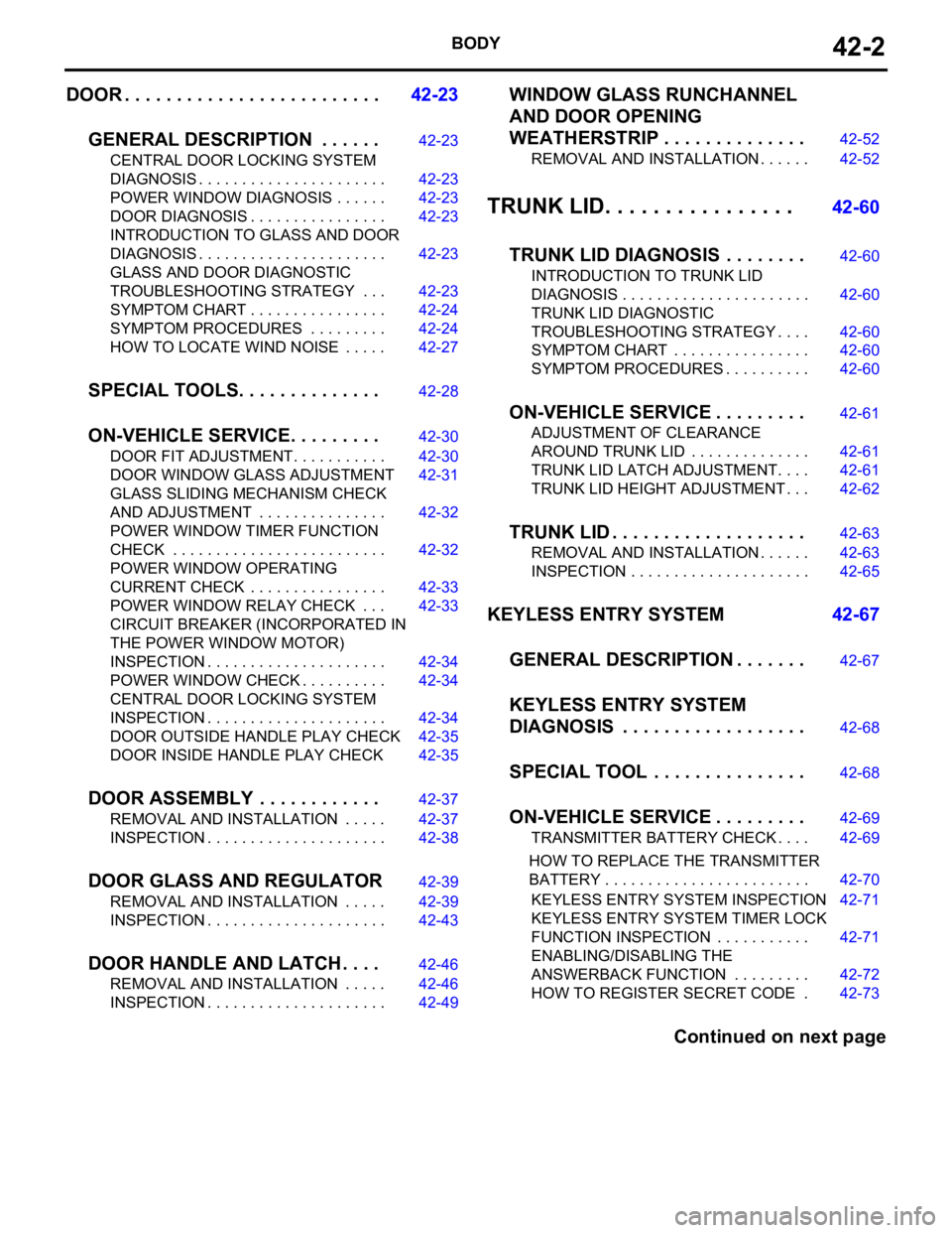
BODY42-2
DOOR . . . . . . . . . . . . . . . . . . . . . . . . .42-23
GENERAL DESCRIPTION . . . . . .
42-23
CENTRAL DOOR LOCKING SYSTEM
DIAGNOSIS . . . . . . . . . . . . . . . . . . . . . . 42-23
POWER WINDOW DIAGNOSIS . . . . . . 42-23
DOOR DIAGNOSIS . . . . . . . . . . . . . . . . 42-23
INTRODUCTION TO GLASS AND DOOR
DIAGNOSIS . . . . . . . . . . . . . . . . . . . . . . 42-23
GLASS AND DOOR DIAGNOSTIC
TROUBLESHOOTING STRATEGY . . . 42-23
SYMPTOM CHART . . . . . . . . . . . . . . . . 42-24
SYMPTOM PROCEDURES . . . . . . . . . 42-24
HOW TO LOCATE WIND NOISE . . . . . 42-27
SPECIAL TOOLS. . . . . . . . . . . . . .42-28
ON-VEHICLE SERVICE. . . . . . . . .42-30
DOOR FIT ADJUSTMENT. . . . . . . . . . . 42-30
DOOR WINDOW GLASS ADJUSTMENT42-31
GLASS SLIDING MECHANISM CHECK
AND ADJUSTMENT . . . . . . . . . . . . . . . 42-32
POWER WINDOW TIMER FUNCTION
CHECK . . . . . . . . . . . . . . . . . . . . . . . . . 42-32
POWER WINDOW OPERATING
CURRENT CHECK . . . . . . . . . . . . . . . . 42-33
POWER WINDOW RELAY CHECK . . . 42-33
CIRCUIT BREAKER (INCORPORATED IN
THE POWER WINDOW MOTOR)
INSPECTION . . . . . . . . . . . . . . . . . . . . . 42-34
POWER WINDOW CHECK . . . . . . . . . . 42-34
CENTRAL DOOR LOCKING SYSTEM
INSPECTION . . . . . . . . . . . . . . . . . . . . . 42-34
DOOR OUTSIDE HANDLE PLAY CHECK42-35
DOOR INSIDE HANDLE PLAY CHECK 42-35
DOOR ASSEMBLY . . . . . . . . . . . .42-37
REMOVAL AND INSTALLATION . . . . . 42-37
INSPECTION . . . . . . . . . . . . . . . . . . . . . 42-38
DOOR GLASS AND REGULATOR42-39
REMOVAL AND INSTALLATION . . . . . 42-39
INSPECTION . . . . . . . . . . . . . . . . . . . . . 42-43
DOOR HANDLE AND LATCH . . . .42-46
REMOVAL AND INSTALLATION . . . . . 42-46
INSPECTION . . . . . . . . . . . . . . . . . . . . . 42-49
WINDOW GLASS RUNCHANNEL
AND DOOR OPENING
WEATHERSTRIP . . . . . . . . . . . . . .
42-52
REMOVAL AND INSTALLATION . . . . . . 42-52
TRUNK LID. . . . . . . . . . . . . . . . 42-60
TRUNK LID DIAGNOSIS . . . . . . . .
42-60
INTRODUCTION TO TRUNK LID
DIAGNOSIS . . . . . . . . . . . . . . . . . . . . . . 42-60
TRUNK LID DIAGNOSTIC
TROUBLESHOOTING STRATEGY . . . . 42-60
SYMPTOM CHART . . . . . . . . . . . . . . . . 42-60
SYMPTOM PROCEDURES . . . . . . . . . . 42-60
ON-VEHICLE SERVICE . . . . . . . . .42-61
ADJUSTMENT OF CLEARANCE
AROUND TRUNK LID . . . . . . . . . . . . . . 42-61
TRUNK LID LATCH ADJUSTMENT. . . . 42-61
TRUNK LID HEIGHT ADJUSTMENT . . . 42-62
TRUNK LID . . . . . . . . . . . . . . . . . . .42-63
REMOVAL AND INSTALLATION . . . . . . 42-63
INSPECTION . . . . . . . . . . . . . . . . . . . . . 42-65
KEYLESS ENTRY SYSTEM 42-67
GENERAL DESCRIPTION . . . . . . .
42-67
KEYLESS ENTRY SYSTEM
DIAGNOSIS . . . . . . . . . . . . . . . . . .
42-68
SPECIAL TOOL . . . . . . . . . . . . . . .42-68
ON-VEHICLE SERVICE . . . . . . . . .42-69
TRANSMITTER BATTERY CHECK . . . . 42-69
HOW TO REPLACE THE TRANSMITTER
BATTERY . . . . . . . . . . . . . . . . . . . . . . . . 42-70
KEYLESS ENTRY SYSTEM INSPECTION42-71
KEYLESS ENTRY SYSTEM TIMER LOCK
FUNCTION INSPECTION . . . . . . . . . . . 42-71
ENABLING/DISABLING THE
ANSWERBACK FUNCTION . . . . . . . . . 42-72
HOW TO REGISTER SECRET CODE . 42-73
Continued on next page
Page 1134 of 1500

KEYLESS ENTRY SYSTEM
BODY42-67
KEYLESS ENTRY SYSTEM
GENERAL DESCRIPTIONBGBJABIE
Antenna and receiver are incorporated in the
ETACS-ECU.
ID code can be registered by using Diagnostic
tool (MUT-III).
Transmitter is a key holder type, which incorpo-
rates lock button, unlock button, trunk button and
panic button
When the transmitter unlock button is pressed
once, the driver's door will be unlocked. If the but-
ton is pressed twice, all the doors will be
unlocked. The adjustment function also allows
you to open all the doors by pressing the unlock
button only once. For further details on using the
multi-center display to adjust the unlock opera-
tion, refer to GROUP 54B, On-vehicle Service
P.54B-486.
When the transmitter is operated, the answer-
back function will work as follows:
The answerback operation can be altered as fol-
lows:NOTE: Enabling/disabling the hazard warning
light flashing, the horn sounding in accordance
with the answerback function. For further details
on using the transmitter to adjust answerback,
P.42-72 see the section below. For further details
on using the multi-center display to adjust
answerback, refer to GROUP 54B, On-vehicle
Service P.54B-486. ITEM OPERATION
DOORS LOCKED DOORS UNLOCKED
Dome light Flashes once Illuminates for 15 seconds
Turn-signal lights (RH and LH) Flashes once Flashes twice
Horn Sounds once when the lock button
is pressed with all the doors locked-
ITEM ADJUSTMENT ITEM ADJUSTMENT DETAIL
Keyless entry system
confirmation by turn
signal lightsAdjustment of hazard answerback
when the transmitter is used to
lock doorsWhen adjusting hazard answerback after the
doors are locked with the transmitter, the
following flashing conditions can be selected.
a. Flash (default)
b. No flash
Adjustment of hazard answerback
when the transmitter is used to
unlock doorsWhen adjusting hazard answerback after the
doors are unlocked with the transmitter, the
following flashing conditions can be selected.
a. Flash (default)
b. No flash
Keyless entry system
confirmation by hornAdjustment of horn answerback
when the transmitter is used to
lock doorsWhen adjusting horn answerback after the
doors are locked with the transmitter, the
following horn conditions can be selected.
a. Horn sounds
b. Horn sounds if doors are already locked
(default)
c. Horn does not sound
Page 1135 of 1500

KEYLESS ENTRY SYSTEM
BODY42-68
If none of the doors is opened or the ignition key
is not inserted in the ignition switch within 30 sec-
onds after the doors are unlocked using the
transmitter, the ETACS-ECU will relock the doors
automatically. This is called "Timer lock function."
This timer lock function prevents accidental
unlocking of doors. The adjustment function
allows you to change the timer lock period from 30 seconds (default setting) to 60, 120 or 180
seconds. For further details on using the
multi-center display (middle grade type) to adjust
the timer lock period, refer to GROUP 54B,
On-vehicle Service P.54B-486.
NOTE: The timer lock period begins when the doors
are unlocked, and ends when the doors is relocked
automatically.
KEYLESS ENTRY SYSTEM DIAGNOSISBGBCJGAI
The keyless entry system is controlled by the Simpli-
fied Wiring System (SWS). Refer to GROUP 54B,
SWS Diagnosis P.54B-57.
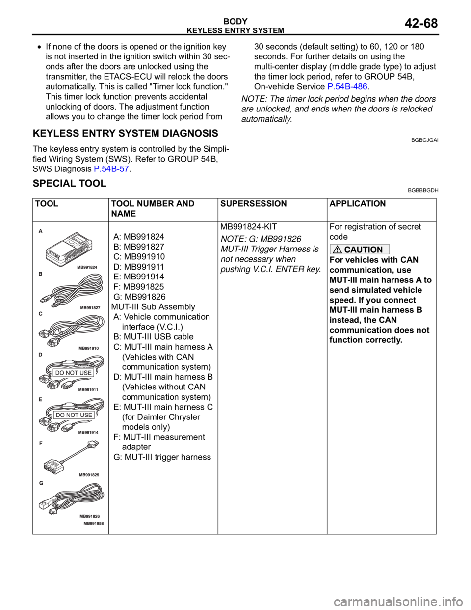
SPECIAL TOOLBGBBBGDH
TOOL TOOL NUMBER AND
NAMESUPERSESSION APPLICATION
A: MB991824
B: MB991827
C: MB991910
D: MB991911
E: MB991914
F: MB991825
G: MB991826
MUT-III Sub Assembly
A: Vehicle communication
interface (V.C.I.)
B: MUT-III USB cable
C: MUT-III main harness A
(Vehicles with CAN
communication system)
D: MUT-III main harness B
(Vehicles without CAN
communication system)
E: MUT-III main harness C
(for Daimler Chrysler
models only)
F: MUT-III measurement
adapter
G: MUT-III trigger harnessMB991824-KIT
NOTE: G: MB991826
MUT-III Trigger Harness is
not necessary when
pushing V.C.I. ENTER key.For registration of secret
code
For vehicles with CAN
communication, use
MUT-III main harness A to
send simulated vehicle
speed. If you connect
MUT-III main harness B
instead, the CAN
communication does not
function correctly.
Page 1136 of 1500

KEYLESS ENTRY SYSTEM
BODY42-69
ON-VEHICLE SERVICE
INSPECTIONM1428003800089
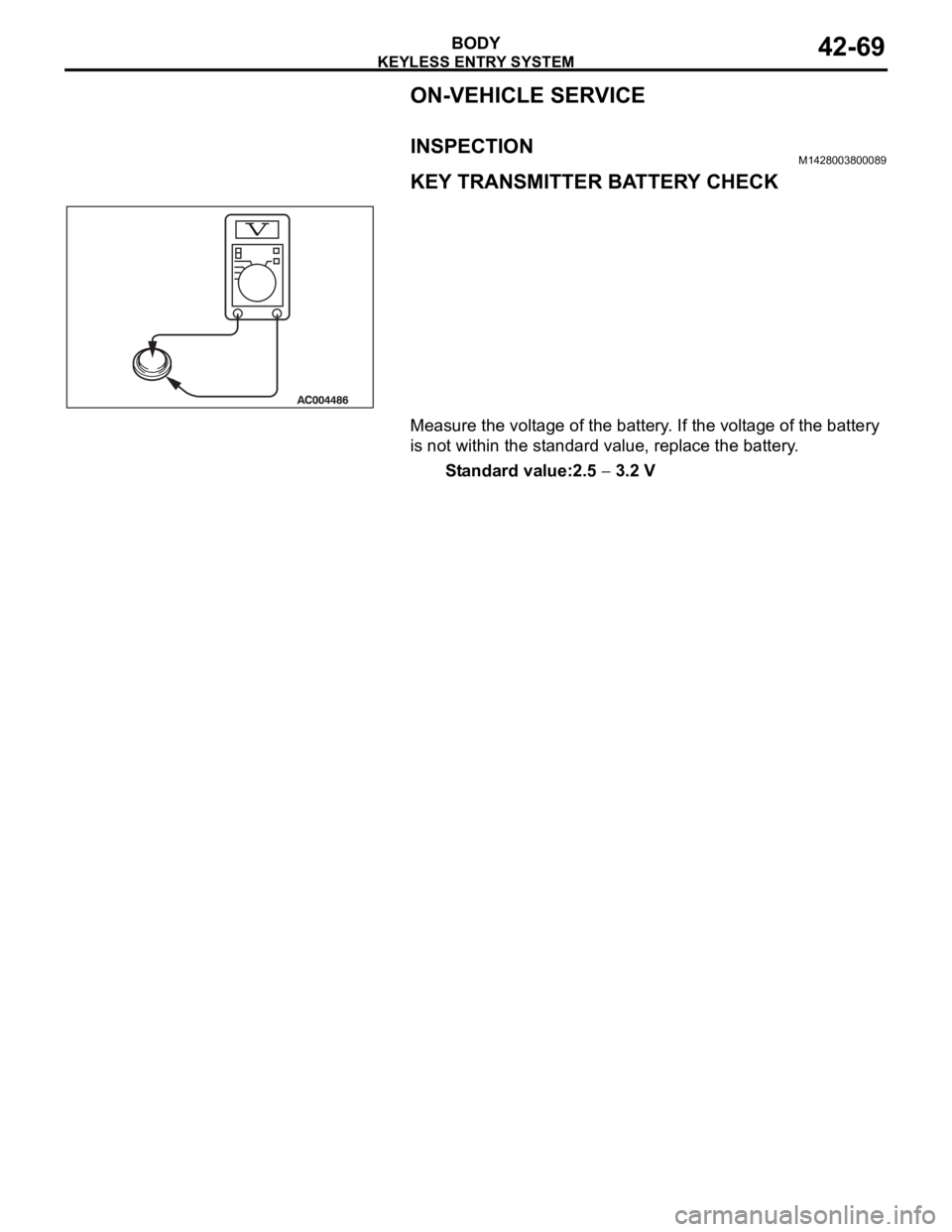
KEY TRANSMITTER BATTERY CHECK
Measure the voltage of the battery. If the voltage of the battery
is not within the standard value, replace the battery.
Standard value:2.5
3.2 V
Page 1137 of 1500

KEYLESS ENTRY SYSTEM
BODY42-70
HOW TO REPLACE THE TRANSMITTER
BATTERY
BGBCHGFB
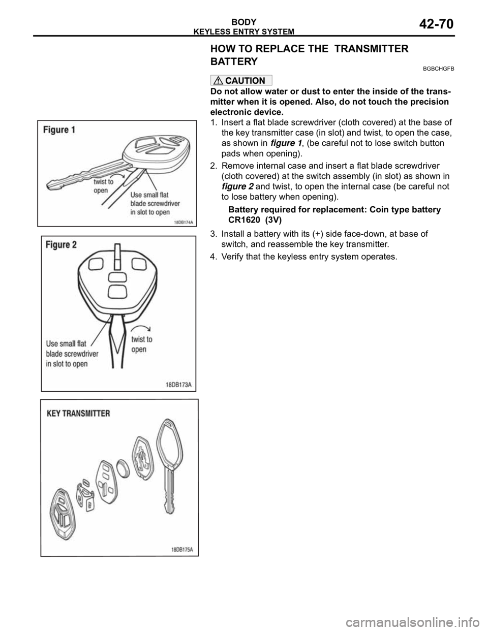
Do not allow water or dust to enter the inside of the trans-
mitter when it is opened. Also, do not touch the precision
electronic device.
1. Insert a flat blade screwdriver (cloth covered) at the base of
the key transmitter case (in slot) and twist, to open the case,
as shown in figure 1, (be careful not to lose switch button
pads when opening).
2. Remove internal case and insert a flat blade screwdriver
(cloth covered) at the switch assembly (in slot) as shown in
figure 2 and twist, to open the internal case (be careful not
to lose battery when opening).
Battery required for replacement: Coin type battery
CR1620 (3V)
3. Install a battery with its (+) side face-down, at base of
switch, and reassemble the key transmitter.
4. Verify that the keyless entry system operates.
Page 1138 of 1500

KEYLESS ENTRY SYSTEM
BODY42-71
KEYLESS ENTRY SYSTEM INSPECTIONBGBHCDAE
Check the following items. If defective, refer to GROUP 54B,
SWS Diagnosis P.54B-10).
1. Operate the transmitter to check that the doors can be
locked and unlocked.
NOTE: The adjustment function allows you to change the
unlock operation setting as follows. Prior to that check, con-
firm which setting is activated.
.
a. When the unlock button is pressed once, the driver's
door will be unlocked. Then when the button is pressed
once again, all the doors will be opened (initial setting).
b. When the unlock button is pressed only once, all the
doors will be opened.
2. Press the trunk lid button of transmitter twice (press once,
and then press again within 5 seconds) and confirm that the
trunk lid opens.
3. Operate the transmitter to check that the answerback
function works in response to doors locking/unlocking.
NOTE: The adjustment function allows you to change the
hazard answerback setting as follows. Prior to that check,
confirm which setting is activated.
.
a. Turn-signal lights: Flash once when doors are locked,
and twice when unlocked (initial setting)
b. Turn-signal lights: Flash once when doors are locked,
but does not flash when unlocked.
c. Turn-signal lights: Do not flash when doors are locked,
but flash twice when unlocked.
d. Turn-signal lights: Do not flash when doors are locked
and unlocked.
NOTE: The adjustment function allows you to change the
horn answerback setting as follows. Prior to that check, con-
firm which setting is activated.
.
a. Horn: Sounds once when the lock button is pressed.
b. Horn: Sounds once when the lock button is pressed (ini-
tial setting).
c. Horn: Does not sound.
KEYLESS ENTRY SYSTEM TIMER LOCK
FUNCTION INSPECTION
BGBEBDIA
If the doors are not locked within 30 seconds after the unlock
button is pressed, refer to GROUP 54B, SWS Diagnosis
P.54B-10.
NOTE: If either of the doors is opened or the key is inserted in
the ignition switch within that 30-second period, the timer lock
function will be cancelled.
Page 1139 of 1500

KEYLESS ENTRY SYSTEM
BODY42-72
NOTE: The adjustment function allows you to change the timer
lock period from 30 seconds (initial setting) to 60, 120 or 180
seconds. Prior to this inspection, confirm which setting is acti-
vated.
ENABLING/DISABLING THE ANSWERBACK
FUNCTION
BGBDGCGD
When the doors are locked or unlocked by using the transmit-
ter, the dome light will flash/illuminate, the turn-signal lights will
flash (hazard answerback), or the horn will sound (horn
answerback) to inform the driver.
The hazard answerback and horn answerback functions can be
enabled or disabled according to the following procedure:
ENABLING/DISABLING THE HAZARD
ANSWERBACK FUNCTION
.
How to adjust hazard answerback when the trans-
mitter is used to lock doors
1. Remove the ignition key.
2. Push the ”unlock” button and then push the ”lock“ button
within 4 seconds to 10 seconds.
3. Release the ”lock” button within 10 seconds after Step 2 and
then release the “unlock” button. The ETACS-ECU tone
alarm will sound, indicating that the hazard answerback
function can be enabled or disabled when the doors are
locked.
Enable the hazard answerback function when the
doors are locked: The ETACS-ECU tone alarm will
sound once.
Disable the hazard answerback function when the
doors are locked: The ETACS-ECU tone alarm will
sound twice.
.
How to adjust hazard answerback when the
transmitter is used to unlock doors
1. Remove the ignition key.
2. Push the ”unlock” button and then push the ”lock“ button
within 4 seconds to 10 seconds.
3. Release the ”lock” button within 10 seconds after Step 2 and
then release the “unlock” button. The ETACS-ECU tone
alarm will sound, indicating that the hazard answerback
function can be enabled or disabled when the door are
unlocked.
Enable the hazard answerback function when the
doors are unlocked: The ETACS-ECU tone alarm
will sound once.
Disable the hazard answerback function when the
doors are unlocked: The ETACS-ECU tone alarm
will sound twice.