jump start MITSUBISHI 380 2005 Workshop Manual
[x] Cancel search | Manufacturer: MITSUBISHI, Model Year: 2005, Model line: 380, Model: MITSUBISHI 380 2005Pages: 1500, PDF Size: 47.87 MB
Page 998 of 1500

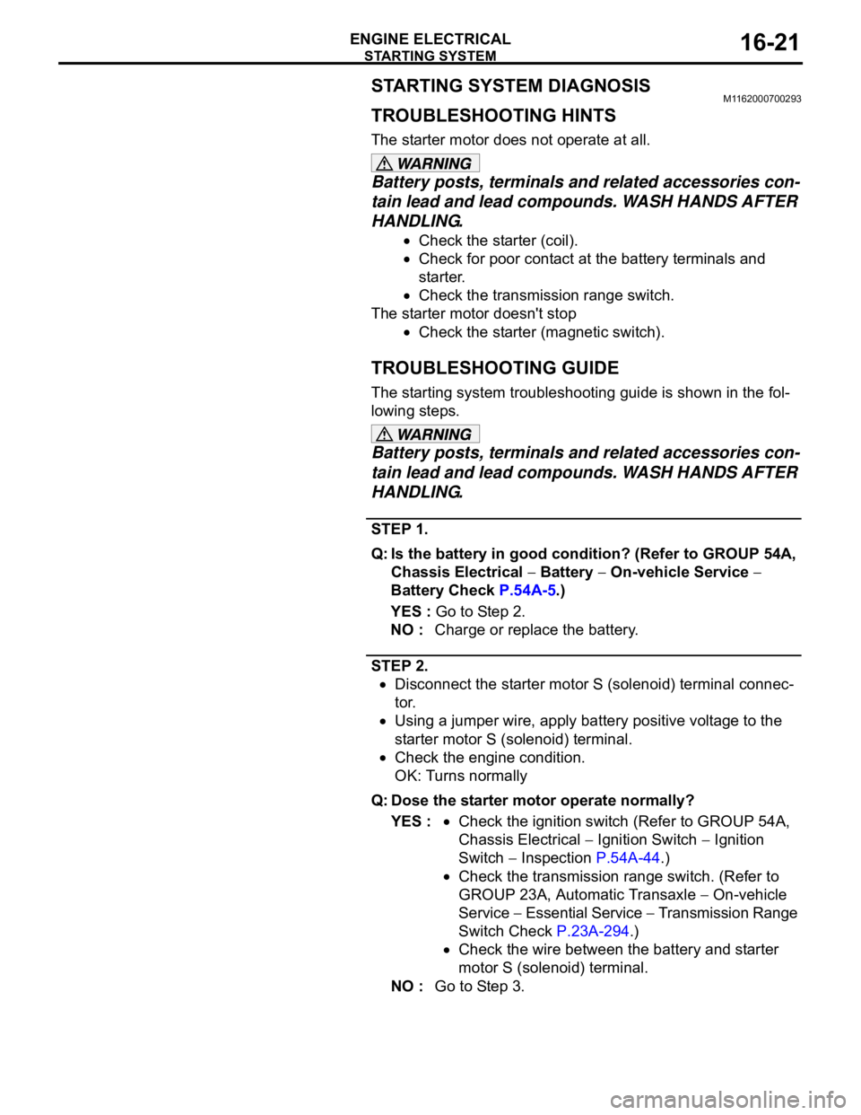
STARTING SYSTEM
ENGINE ELECTRICAL16-21
STARTING SYSTEM DIAGNOSISM1162000700293
TROUBLESHOOTING HINTS
The starter motor does not operate at all.
Battery posts, terminals and related accessories con-
tain lead and lead compounds. WASH HANDS AFTER
HANDLING.
Check the starter (coil).
Check for poor contact at the battery terminals and
starter.
Check the transmission range switch.
The starter motor doesn't stop
Check the starter (magnetic switch).
TROUBLESHOOTING GUIDE
The starting system troubleshooting guide is shown in the fol-
lowing steps.
Battery posts, terminals and related accessories con-
tain lead and lead compounds. WASH HANDS AFTER
HANDLING.
STEP 1.
Q: Is the battery in good condition? (Refer to GROUP 54A,
Chassis Electrical
Battery On-vehicle Service
Battery Check P.54A-5.)
YES : Go to Step 2.
NO : Charge or replace the battery.
STEP 2.
Disconnect the starter motor S (solenoid) terminal connec-
tor.
Using a jumper wire, apply battery positive voltage to the
starter motor S (solenoid) terminal.
Check the engine condition.
OK: Turns normally
Q: Dose the starter motor operate normally?
YES :
Check the ignition switch (Refer to GROUP 54A,
Chassis Electrical
Ignition Switch Ignition
Switch
Inspection P.54A-44.)
Check the transmission range switch. (Refer to
GROUP 23A, Automatic Transaxle
On-vehicle
Service
Essential Service Transmission Range
Switch Check P.23A-294.)
Check the wire between the battery and starter
motor S (solenoid) terminal.
NO : Go to Step 3.
Page 1169 of 1500

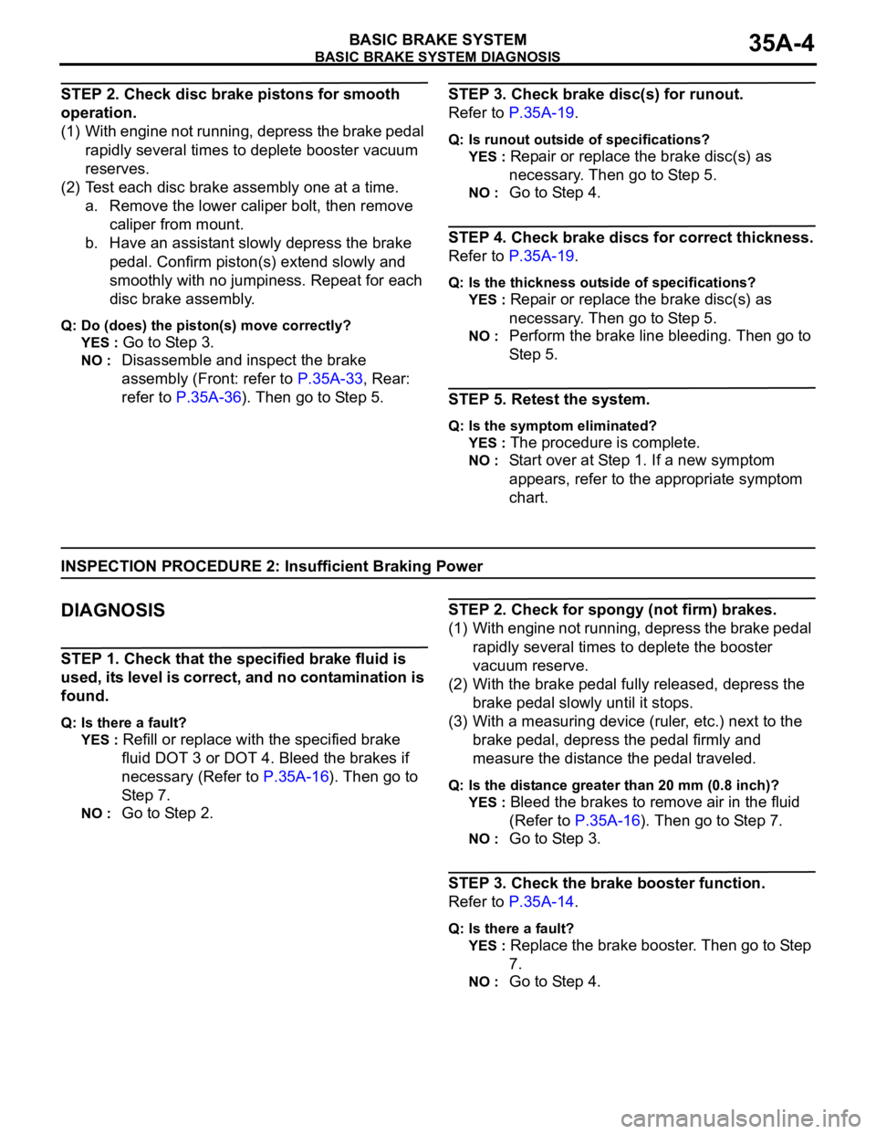
BASIC BRAKE SYSTEM DIAGNOSIS
BASIC BRAKE SYSTEM35A-4
STEP 2. Check disc brake pistons for smooth
operation.
(1) With engine not running, depress the brake pedal
rapidly several times to deplete booster vacuum
reserves.
(2) Test each disc brake assembly one at a time.
a. Remove the lower caliper bolt, then remove
caliper from mount.
b. Have an assistant slowly depress the brake
pedal. Confirm piston(s) extend slowly and
smoothly with no jumpiness. Repeat for each
disc brake assembly.
Q: Do (does) the piston(s) move correctly?
YES :
Go to Step 3.
NO : Disassemble and inspect the brake
assembly (Front: refer to P.35A-33, Rear:
refer to P.35A-36). Then go to Step 5.
STEP 3. Check brake disc(s) for runout.
Refer to P.35A-19.
Q: Is runout outside of specifications?
YES :
Repair or replace the brake disc(s) as
necessary. Then go to Step 5.
NO : Go to Step 4.
STEP 4. Check brake discs for correct thickness.
Refer to P.35A-19.
Q: Is the thickness outside of specifications?
YES :
Repair or replace the brake disc(s) as
necessary. Then go to Step 5.
NO : Perform the brake line bleeding. Then go to
St e p 5.
STEP 5. Retest the system.
Q: Is the symptom eliminated?
YES :
The procedure is complete.
NO : Start over at Step 1. If a new symptom
appears, refer to the appropriate symptom
chart.
INSPECTION PROCEDURE 2: Insufficient Braking Power
.
DIAGNOSIS
STEP 1. Check that the specified brake fluid is
used, its level is correct, and no contamination is
found.
Q: Is there a fault?
YES :
Refill or replace with the specified brake
fluid DOT 3 or DOT 4. Bleed the brakes if
necessary (Refer to P.35A-16). Then go to
Step 7.
NO : Go to Step 2.
STEP 2. Check for spongy (not firm) brakes.
(1) With engine not running, depress the brake pedal
rapidly several times to deplete the booster
vacuum reserve.
(2) With the brake pedal fully released, depress the
brake pedal slowly until it stops.
(3) With a measuring device (ruler, etc.) next to the
brake pedal, depress the pedal firmly and
measure the distance the pedal traveled.
Q: Is the distance greater than 20 mm (0.8 inch)?
YES :
Bleed the brakes to remove air in the fluid
(Refer to P.35A-16). Then go to Step 7.
NO : Go to Step 3.
STEP 3. Check the brake booster function.
Refer to P.35A-14.
Q: Is there a fault?
YES :
Replace the brake booster. Then go to Step
7.
NO : Go to Step 4.