reset MITSUBISHI 380 2005 Owner's Manual
[x] Cancel search | Manufacturer: MITSUBISHI, Model Year: 2005, Model line: 380, Model: MITSUBISHI 380 2005Pages: 1500, PDF Size: 47.87 MB
Page 829 of 1500

AUTO A/C DIAGNOSIS
HEATER, AIR CONDITIONING AND VENTILATION55-128
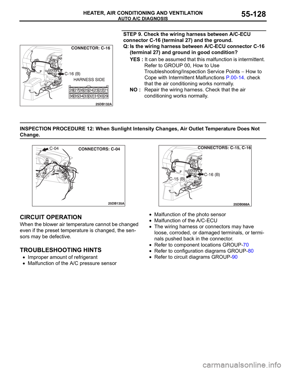
STEP 9. Check the wiring harness between A/C-ECU
connector C-16 (terminal 27) and the ground.
Q: Is the wiring harness between A/C-ECU connector C-16
(terminal 27) and ground in good condition?
YES : It can be assumed that this malfunction is intermittent.
Refer to GROUP 00, How to Use
Troubleshooting/Inspection Service Points
How to
Cope with Intermittent Malfunctions P.00-14. check
that the air conditioning works normally.
NO : Repair the wiring harness. Check that the air
conditioning works normally.
INSPECTION PROCEDURE 12: When Sunlight Intensity Changes, Air Outlet Temperature Does Not
Change.
.
CIRCUIT OPERATION
When the blower air temperature cannot be changed
even if the preset temperature is changed, the sen-
sors may be defective.
.
TROUBLESHOOTING HINTS
Improper amount of refrigerant
Malfunction of the A/C pressure sensor
Malfunction of the photo sensor
Malfunction of the A/C-ECU
The wiring harness or connectors may have
loose, corroded, or damaged terminals, or termi-
nals pushed back in the connector.
Refer to component locations GROUP-70
Refer to configuration diagrams GROUP-80
Refer to circuit diagrams GROUP-90
Page 848 of 1500

ON-VEHICLE SERVICE
HEATER, AIR CONDITIONING AND VENTILATION55-147
TEST PROCEDURES
1. Select a quiet area for testing.
2. Duplicate problem (customer complaint) as much as
possible.
3. Judge if the noise is abnormal (ie. it is important to
understand the characteristics of the vehicle and its normal
state to judge what is abnormal) - Compare with similar
vehicle if necessary.
4. Detail what and how noise occurs.
5. Find the noise source and verify its transmission by isolating
the subject part from the vehicle.
6. Repair the problem.
7. Explain and report your findings.
DETAILS OF A/C NOISE
POSSIBLE CAUSES, CHECKS AND REPAIRS
NOISE DESCRIPTION WHEN IT OCCURS SOURCE OF NOISE
Rumbling (Bearing noise) With A/C On or Off Magnetic clutch, idler pulley
Clang-Clack noise When compressor is engaged Magnetic clutch operation
Squawking (Belt sliding noise) When compressor is engaged V-belt
Whistling or Whooping noise Immediately after the A/C is
engaged.Expansion valve
Hissing or swishing noise When A/C is engaged, but
decreases as flow is stable Refrigerant flow
Rattling (Internal compressor) When compressor is operating Compressor internal part
Wooing (Resonant noise) With A/C On, occurs at certain
speed.Resonance of accessories
Cooing (Discharge pulsation
noise)With A/C On or Off Resonating noise with the vehicle
body
NOISE DESCRIPTION POSSIBLE CAUSE CHECK REPAIR
Rumbling (Bearing
noise)Bearing damage in rotor Manual rotation of bearing Replace compressor
Rotor slipping on boss Wear on compressor boss
surfaceReplace compressor
Bearing damage in pulley Check alignment between
pulleysReplace compressor
Clang-Clack noise Hub to stator misaligned Wear on inner clutch face Replace compressor
Gap between clutch
surface is too largeCheck Air gap is within
specificationReplace compressor
Squawking (Belt sliding
noise)Oil/water between the belt
and rotor surfaceOil and water
contaminationClean
Low belt tension Belt tension Reset or Replace belt and
set tension to correct
specification
Whistling or Whooping
noiseVibration of expansion
valveExpansion valve Replace TX valve
Page 1237 of 1500

HOW TO USE TROUBLESHOOTING/INSPECTION SERVICE POINTS
GENERAL00-16
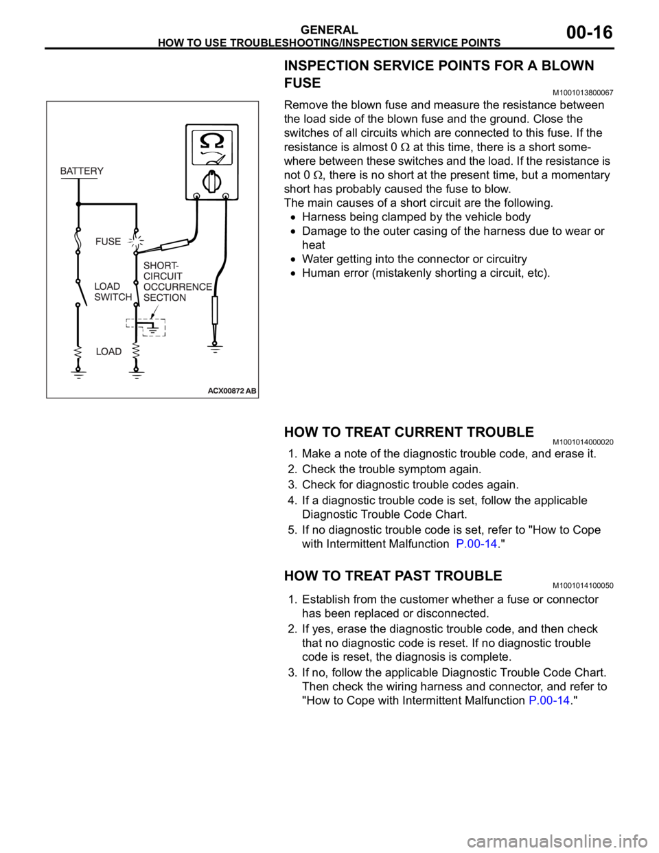
INSPECTION SERVICE POINTS FOR A BLOWN
FUSE
M1001013800067
Remove the blown fuse and measure the resistance between
the load side of the blown fuse and the ground. Close the
switches of all circuits which are connected to this fuse. If the
resistance is almost 0
at this time, there is a short some-
where between these switches and the load. If the resistance is
not 0
, there is no short at the present time, but a momentary
short has probably caused the fuse to blow.
The main causes of a short circuit are the following.
Harness being clamped by the vehicle body
Damage to the outer casing of the harness due to wear or
heat
Water getting into the connector or circuitry
Human error (mistakenly shorting a circuit, etc).
HOW TO TREAT CURRENT TROUBLEM1001014000020
1. Make a note of the diagnostic trouble code, and erase it.
2. Check the trouble symptom again.
3. Check for diagnostic trouble codes again.
4. If a diagnostic trouble code is set, follow the applicable
Diagnostic Trouble Code Chart.
5. If no diagnostic trouble code is set, refer to "How to Cope
with Intermittent Malfunction P.00-14."
HOW TO TREAT PAST TROUBLEM1001014100050
1. Establish from the customer whether a fuse or connector
has been replaced or disconnected.
2. If yes, erase the diagnostic trouble code, and then check
that no diagnostic code is reset. If no diagnostic trouble
code is reset, the diagnosis is complete.
3. If no, follow the applicable Diagnostic Trouble Code Chart.
Then check the wiring harness and connector, and refer to
"How to Cope with Intermittent Malfunction P.00-14."
Page 1282 of 1500

TRACTION CONTROL SYSTEM (TCL) DIAGNOSIS
TRACTION CONTROL SYSTEM (TCL)13C-3
TRACTION CONTROL SYSTEM (TCL) DIAGNOSIS
INTRODUCTION TO TRACTION CONTROL SYSTEM (TCL) DIAGNOSISM1136004600026
TCL Diagnostic Trouble Code Detection
Conditions
TCL diagnostic trouble codes (TCL DTCs) are set
under different conditions, depending on the mal-
function detected. Most TCL DTCs will only be set
during vehicle operation. Some TCL DTCs will also
be set during the TCL self-check immediately after
the engine is started. When you check if an TCL DTC will be displayed again after the DTC has been
erased, you should recreate the TCL DTC set condi-
tions. Depending on the detection timing and set
conditions for the specific TCL DTC, you must either
drive the vehicle or turn the engine off and restart it.
To set the proper conditions for that DTC again, refer
to "TCL DTC SET CONDITIONS" for each TCL DTC
that you are trying to reset.
TROUBLESHOOTING STRATEGYM1136003100062
Use these steps to plan your diagnostic strategy. If
you follow them carefully, you will check most of the
possible causes of a TCL problem.
1. Gather information from the customer.
2. Verify that the condition described by the
customer exists.
3. Check the vehicle for any TCL DTC. (Refer to
P.13C-3, Diagnosis Function
How to Read and
Erase Diagnostic Trouble Codes).
4. If you can verify the condition but no TCL DTCs
are set, and the malfunction may be intermittent.
(Refer to GROUP 00, How to Use
Troubleshooting/Inspection Service Points
How
to Cope with Intermittent Malfunctions P.00-14).
5. If you can verify the condition but there is no TCL
DTCs, or the system cannot communicate with
diagnostic tool MB991958 (MUT-III sub
assembly), and find the fault. (Refer to P.13C-23,
Symptom Chart).6. If there is a TCL DTC, record the number of the
code, then erase the code from vehicle memory
using the diagnostic tool MB991958 (MUT-III sub
assembly). (Refer to P.13C-3, Diagnosis Function
How to Read and Erase Diagnostic Trouble
Codes).
7. Re-create the TCL DTC set conditions to see if
the same TCL DTC will set again. (Refer to
P.13C-3, Diagnosis Function
How to Read and
Erase Diagnostic Trouble Codes).
If the same TCL DTC sets again, perform the
diagnostic procedures for the set code. (Refer to
P.13C-8, Diagnostic Trouble Code Chart).
NOTE: If the ABS-8 ECU or the active wheel
speed sensor are disconnected, or if the wir-
ing is an open/ short circuit, the ABS 8 ECU
will shut off power supply to the respective
wheel speed sensor. All other wheel speed
sensors will operate normally. To restore the
power supply, the ignition switch must be
turned to the "OFF" position then to the "ON"
position again.
DIAGNOSIS FUNCTIONM1136003200025
HOW TO CONNECT THE DIAGNOSTIC TOOL
(MUT-III)
Required Special Tools:
MB991958: Diagnostic Tool (MUT-III Sub Assembly)
MB991824: Vehicle Communication Interface (V.C.I.)
MB991827: MUT-III USB Cable
MB991910: MUT-III Main Harness A