engine MITSUBISHI 380 2005 Workshop Manual
[x] Cancel search | Manufacturer: MITSUBISHI, Model Year: 2005, Model line: 380, Model: MITSUBISHI 380 2005Pages: 1500, PDF Size: 47.87 MB
Page 1494 of 1500

AUTOMATIC TRANSMISSION DIAGNOSIS
AUTOMATIC TRANSMISSION23A-35
SYMPTOM CHART M1231008000277
During diagnosis, a DTC code associated with
other system may be set when the ignition switch
is turned on with connector(s) disconnected. On
completion, confirm all systems for DTC code(s).
If DTC code(s) are set, erase them all.
SYMPTOM INSPECTION
PROCEDURE NO.REFERENCE
PA G E
Communication with diagnostic
tool is not possibleCommunication with all systems
is impossible- Group 13B
Symptom
Procedures
13A-539.
Communication with the
A/T-ECU only is impossible- Group 13B
Symptom
Procedures
13A-541.
Driving impossible Engine does not start 1
P.23A-218
Does not move forward 2
P.23A-220
Does not move backward 3
P.23A-223
Does not move (forward and
backward)4
P.23A-226
Malfunction when moving
selector into gearEngine stalls when moving
selector lever from "N" to "D" or
"N" to "R"5
P.23A-227
Shift shock when shifting from
"N" to "D" and long delay6
P.23A-229
Shift shock when shifting from
"N" to "R" and long delay 7
P.23A-232
Shift shock when shifting from
"N" to "D" and "N" to "R" and
long delay 8
P.23A-235
Malfunction when shifting Shift shock and slipping 9
P.23A-236
Does not shift properly Early or late shifting in all gears 10
P.23A-239
Early or late shifting in some
gears11
P.23A-242
Does not shift No diagnostic trouble codes 12
P.23A-244
Malfunction while driving Poor acceleration 13
P.23A-248
Vibration 14
P.23A-250
Shift switch assembly system 15
P.23A-252
Shift position indicator light system
P.23A-269
Page 1495 of 1500

AUTOMATIC TRANSMISSION DIAGNOSIS
AUTOMATIC TRANSMISSION23A-36
DIAGNOSTIC TROUBLE CODE PROCEDURES
(P0713): Transmission Fluid Temperature Sensor System (Open Circuit)
.
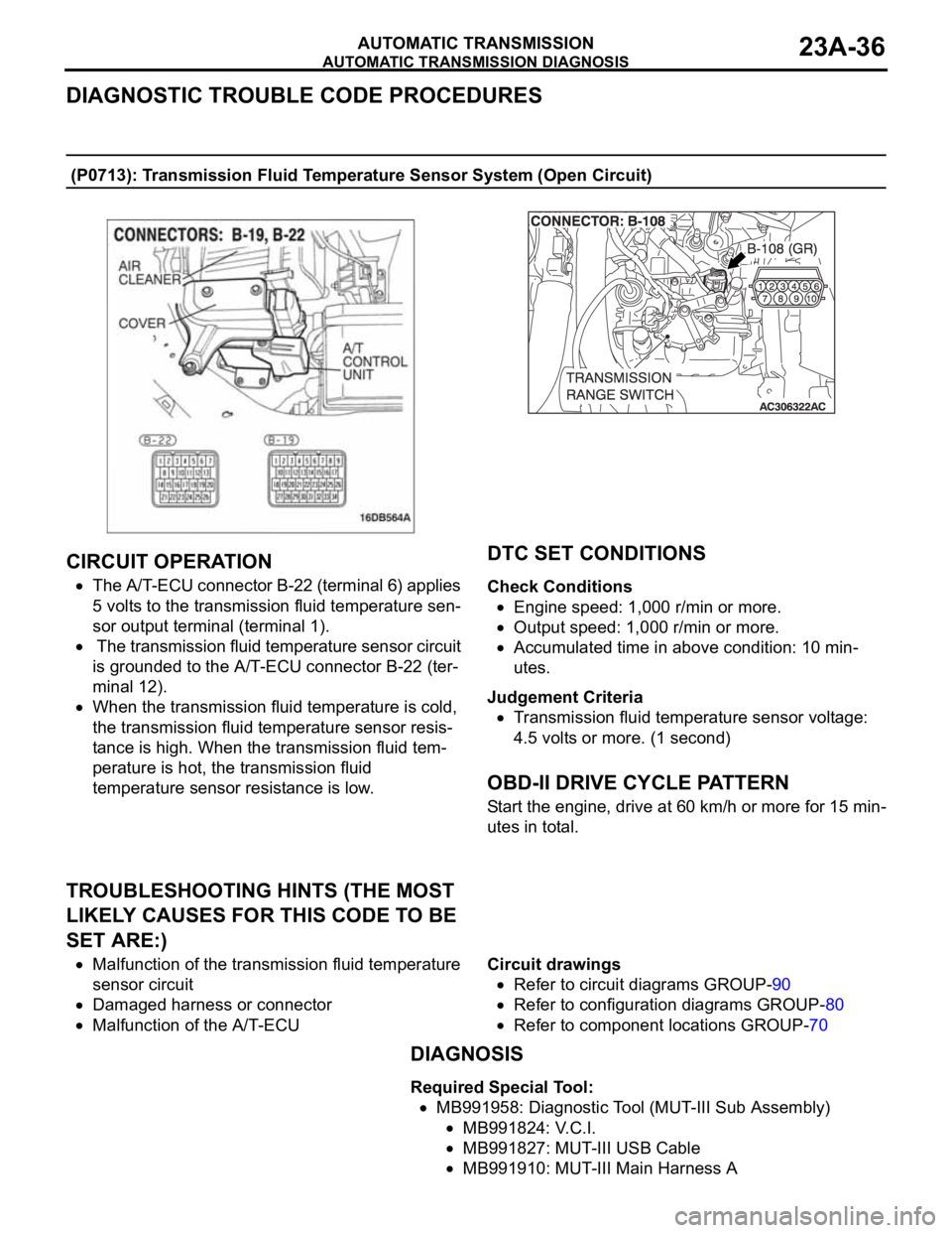
CIRCUIT OPERATION
The A/T-ECU connector B-22 (terminal 6) applies
5 volts to the transmission fluid temperature sen-
sor output terminal (terminal 1).
The transmission fluid temperature sensor circuit
is grounded to the A/T-ECU connector B-22 (ter-
minal 12).
When the transmission fluid temperature is cold,
the transmission fluid temperature sensor resis-
tance is high. When the transmission fluid tem-
perature is hot, the transmission fluid
temperature sensor resistance is low.
.
DTC SET CONDITIONS
Check Conditions
Engine speed: 1,000 r/min or more.
Output speed: 1,000 r/min or more.
Accumulated time in above condition: 10 min-
utes.
Judgement Criteria
Transmission fluid temperature sensor voltage:
4.5 volts or more. (1 second)
.
OBD-II DRIVE CYCLE PATTERN
Start the engine, drive at 60 km/h or more for 15 min-
utes in total.
.
TROUBLESHOOTING HINTS (THE MOST
LIKELY CAUSES FOR THIS CODE TO BE
SET ARE:)
Malfunction of the transmission fluid temperature
sensor circuit
Damaged harness or connector
Malfunction of the A/T-ECUCircuit drawings
Refer to circuit diagrams GROUP-90
Refer to configuration diagrams GROUP-80
Refer to component locations GROUP-70
DIAGNOSIS
Required Special Tool:
MB991958: Diagnostic Tool (MUT-III Sub Assembly)
MB991824: V.C.I.
MB991827: MUT-III USB Cable
MB991910: MUT-III Main Harness A
Page 1496 of 1500

AUTOMATIC TRANSMISSION DIAGNOSIS
AUTOMATIC TRANSMISSION23A-37
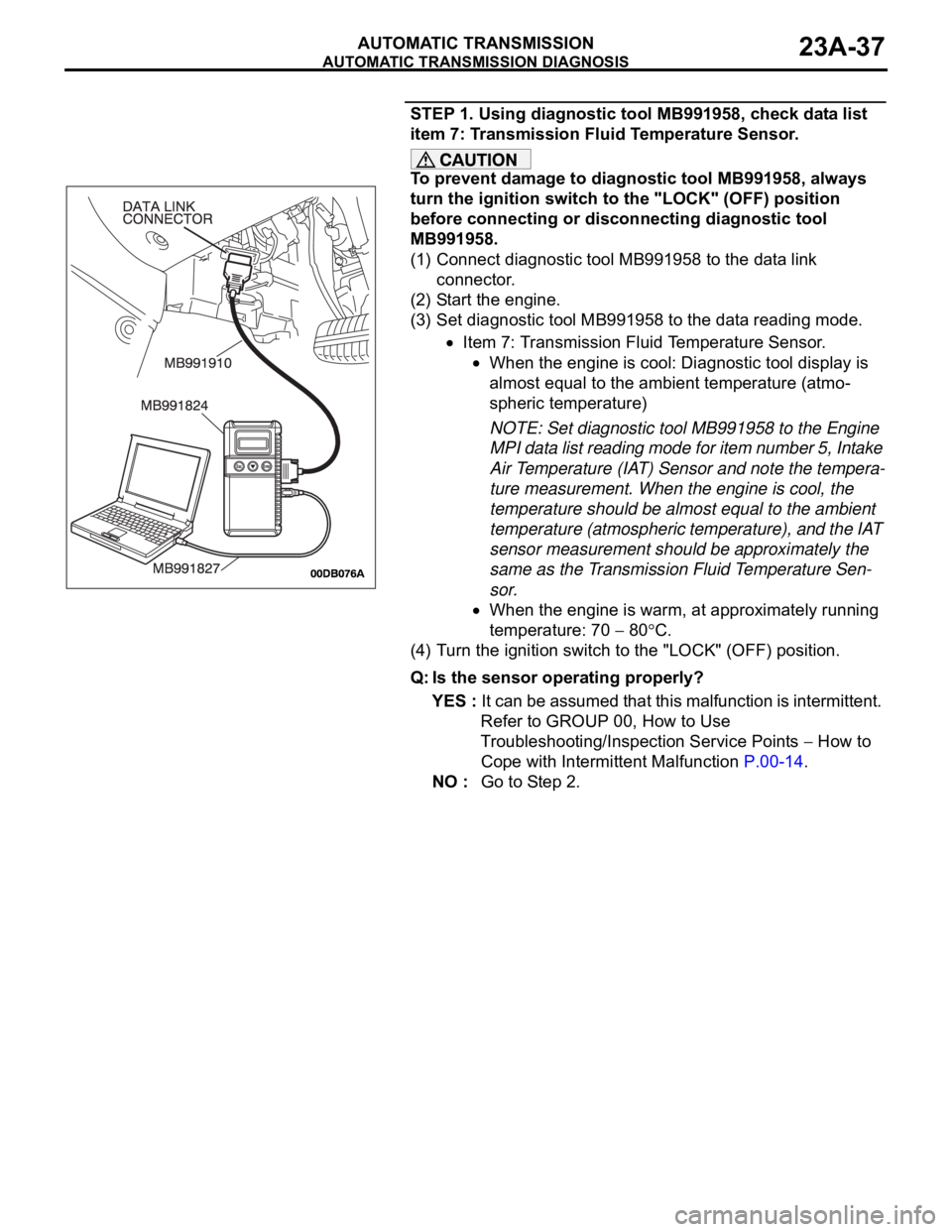
STEP 1. Using diagnostic tool MB991958, check data list
item 7: Transmission Fluid Temperature Sensor.
To prevent damage to diagnostic tool MB991958, always
turn the ignition switch to the "LOCK" (OFF) position
before connecting or disconnecting diagnostic tool
MB991958.
(1) Connect diagnostic tool MB991958 to the data link
connector.
(2) Start the engine.
(3) Set diagnostic tool MB991958 to the data reading mode.
Item 7: Transmission Fluid Temperature Sensor.
When the engine is cool: Diagnostic tool display is
almost equal to the ambient temperature (atmo-
spheric temperature)
NOTE: Set diagnostic tool MB991958 to the Engine
MPI data list reading mode for item number 5, Intake
Air Temperature (IAT) Sensor and note the tempera-
ture measurement. When the engine is cool, the
temperature should be almost equal to the ambient
temperature (atmospheric temperature), and the IAT
sensor measurement should be approximately the
same as the Transmission Fluid Temperature Sen-
sor.
When the engine is warm, at approximately running
temperature: 70
80C.
(4) Turn the ignition switch to the "LOCK" (OFF) position.
Q: Is the sensor operating properly?
YES : It can be assumed that this malfunction is intermittent.
Refer to GROUP 00, How to Use
Troubleshooting/Inspection Service Points
How to
Cope with Intermittent Malfunction P.00-14.
NO : Go to Step 2.
Page 1500 of 1500

AUTOMATIC TRANSMISSION DIAGNOSIS
AUTOMATIC TRANSMISSION23A-41
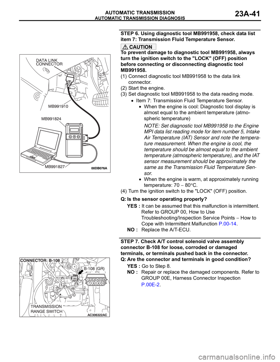
STEP 6. Using diagnostic tool MB991958, check data list
item 7: Transmission Fluid Temperature Sensor.
To prevent damage to diagnostic tool MB991958, always
turn the ignition switch to the "LOCK" (OFF) position
before connecting or disconnecting diagnostic tool
MB991958.
(1) Connect diagnostic tool MB991958 to the data link
connector.
(2) Start the engine.
(3) Set diagnostic tool MB991958 to the data reading mode.
Item 7: Transmission Fluid Temperature Sensor.
When the engine is cool: Diagnostic tool display is
almost equal to the ambient temperature (atmo-
spheric temperature)
NOTE: Set diagnostic tool MB991958 to the Engine
MPI data list reading mode for item number 5, Intake
Air Temperature (IAT) Sensor and note the tempera-
ture measurement. When the engine is cool, the
temperature should be almost equal to the ambient
temperature (atmospheric temperature), and the IAT
sensor measurement should be approximately the
same as the Transmission Fluid Temperature Sen-
sor.
When the engine is warm, at approximately running
temperature: 70
80C.
(4) Turn the ignition switch to the "LOCK" (OFF) position.
Q: Is the sensor operating properly?
YES : It can be assumed that this malfunction is intermittent.
Refer to GROUP 00, How to Use
Troubleshooting/Inspection Service Points
How to
Cope with Intermittent Malfunction P.00-14.
NO : Replace the A/T-ECU.
STEP 7. Check A/T control solenoid valve assembly
connector B-108 for loose, corroded or damaged
terminals, or terminals pushed back in the connector.
Q: Are the connector and terminals in good condition?
YES : Go to Step 8.
NO : Repair or replace the damaged components. Refer to
GROUP 00E, Harness Connector Inspection
P.00E-2.