engine MITSUBISHI 380 2005 Workshop Manual
[x] Cancel search | Manufacturer: MITSUBISHI, Model Year: 2005, Model line: 380, Model: MITSUBISHI 380 2005Pages: 1500, PDF Size: 47.87 MB
Page 1407 of 1500
EMISSION CONTROL
ENGINE AND EMISSION CONTROL17-76
EMISSION CONTROL
GENERAL DESCRIPTIONM1173000100314
The emission control system consists of the fol-
lowing subsystems:
Positive crankcase ventilation system
Evaporative emission system
Exhaust emission control system
DIAGNOSISM1173000700112
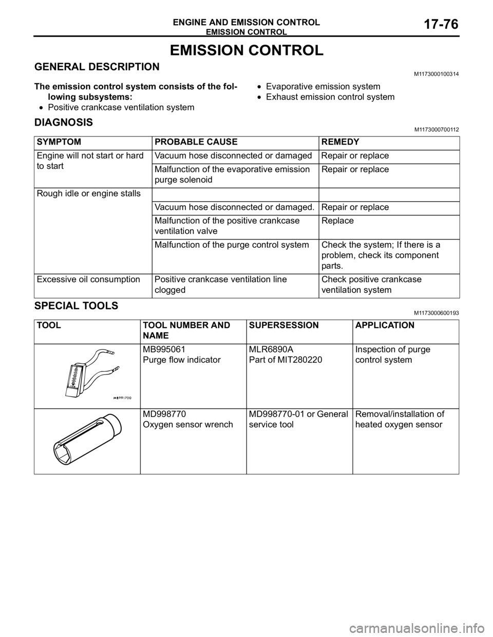
SPECIAL TOOLSM1173000600193
SYMPTOM PROBABLE CAUSE REMEDY
Engine will not start or hard
to startVacuum hose disconnected or damaged Repair or replace
Malfunction of the evaporative emission
purge solenoidRepair or replace
Rough idle or engine stalls
Vacuum hose disconnected or damaged. Repair or replace
Malfunction of the positive crankcase
ventilation valveReplace
Malfunction of the purge control system Check the system; If there is a
problem, check its component
parts.
Excessive oil consumption Positive crankcase ventilation line
cloggedCheck positive crankcase
ventilation system
TOOL TOOL NUMBER AND
NAMESUPERSESSION APPLICATION
MB995061
Purge flow indicatorMLR6890A
Part of MIT280220Inspection of purge
control system
MD998770
Oxygen sensor wrenchMD998770-01 or General
service toolRemoval/installation of
heated oxygen sensor
Page 1408 of 1500
EMISSION CONTROL
ENGINE AND EMISSION CONTROL17-77
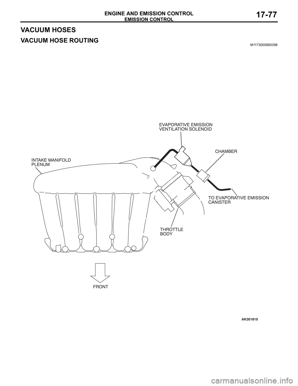
VACUUM HOSES
VACUUM HOSE ROUTINGM1173000900398
Page 1409 of 1500
EMISSION CONTROL
ENGINE AND EMISSION CONTROL17-78
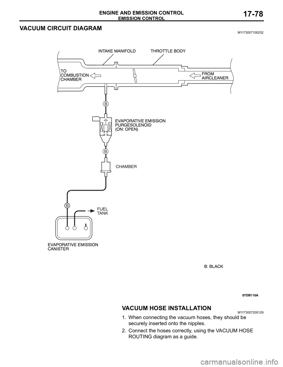
VACUUM CIRCUIT DIAGRAMM1173007100252
VACUUM HOSE INSTALLATIONM1173007200129
1. When connecting the vacuum hoses, they should be
securely inserted onto the nipples.
2. Connect the hoses correctly, using the VACUUM HOSE
ROUTING diagram as a guide.
Page 1410 of 1500
EMISSION CONTROL
ENGINE AND EMISSION CONTROL17-79
VACUUM HOSE CHECKM1173007300171
1. Using the VACUUM HOSE ROUTING diagram as a guide,
check that the vacuum hoses are correctly connected.
2. Check the connection of the vacuum hoses, (removed,
loose, etc.) and confirm that there are no sharp bends or
damage.
POSITIVE CRANKCASE VENTILATION SYSTEM
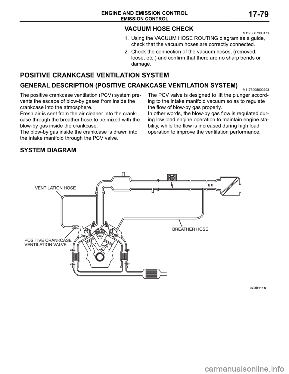
GENERAL DESCRIPTION (POSITIVE CRANKCASE VENTILATION SYSTEM)M1173005000293
The positive crankcase ventilation (PCV) system pre-
vents the escape of blow-by gases from inside the
crankcase into the atmosphere.
Fresh air is sent from the air cleaner into the crank-
case through the breather hose to be mixed with the
blow-by gas inside the crankcase.
The blow-by gas inside the crankcase is drawn into
the intake manifold through the PCV valve.The PCV valve is designed to lift the plunger accord-
ing to the intake manifold vacuum so as to regulate
the flow of blow-by gas properly.
In other words, the blow-by gas flow is regulated dur-
ing low load engine operation to maintain engine sta-
bility, while the flow is increased during high load
operation to improve the ventilation performance.
SYSTEM DIAGRAM
Page 1411 of 1500
EMISSION CONTROL
ENGINE AND EMISSION CONTROL17-80
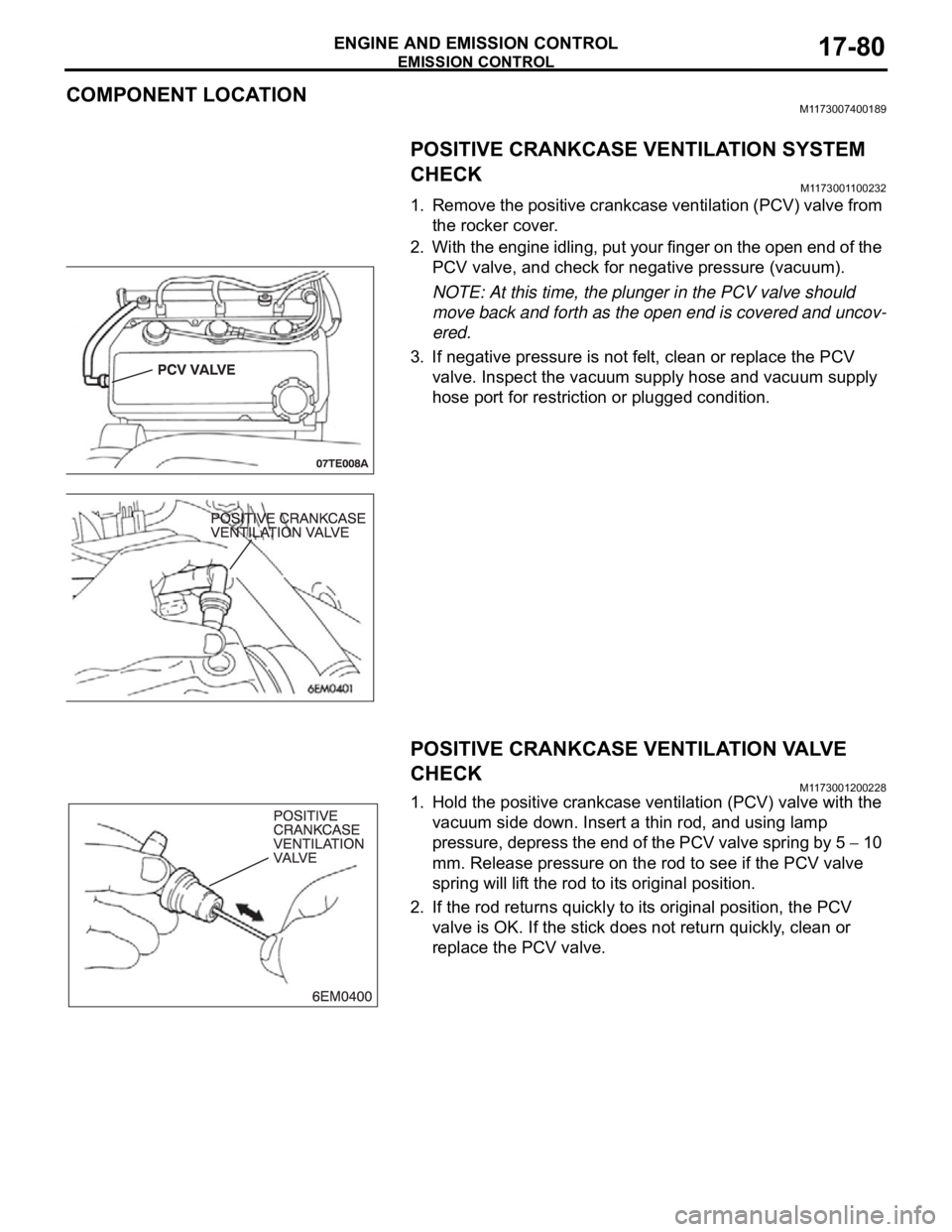
COMPONENT LOCATIONM1173007400189
POSITIVE CRANKCASE VENTILATION SYSTEM
CHECK
M1173001100232
1. Remove the positive crankcase ventilation (PCV) valve from
the rocker cover.
2. With the engine idling, put your finger on the open end of the
PCV valve, and check for negative pressure (vacuum).
NOTE: At this time, the plunger in the PCV valve should
move back and forth as the open end is covered and uncov-
ered.
3. If negative pressure is not felt, clean or replace the PCV
valve. Inspect the vacuum supply hose and vacuum supply
hose port for restriction or plugged condition.
POSITIVE CRANKCASE VENTILATION VALVE
CHECK
M1173001200228
1. Hold the positive crankcase ventilation (PCV) valve with the
vacuum side down. Insert a thin rod, and using lamp
pressure, depress the end of the PCV valve spring by 5
10
mm. Release pressure on the rod to see if the PCV valve
spring will lift the rod to its original position.
2. If the rod returns quickly to its original position, the PCV
valve is OK. If the stick does not return quickly, clean or
replace the PCV valve.
Page 1412 of 1500
EMISSION CONTROL
ENGINE AND EMISSION CONTROL17-81
EVAPORATIVE EMISSION CONTROL SYSTEM
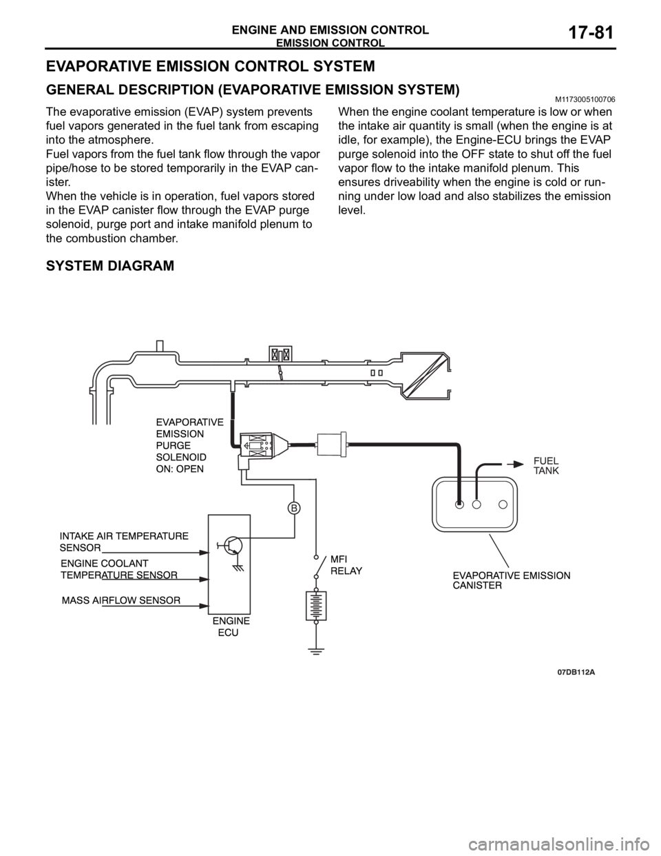
GENERAL DESCRIPTION (EVAPORATIVE EMISSION SYSTEM)M1173005100706
The evaporative emission (EVAP) system prevents
fuel vapors generated in the fuel tank from escaping
into the atmosphere.
Fuel vapors from the fuel tank flow through the vapor
pipe/hose to be stored temporarily in the EVAP can-
ister.
When the vehicle is in operation, fuel vapors stored
in the EVAP canister flow through the EVAP purge
solenoid, purge port and intake manifold plenum to
the combustion chamber.When the engine coolant temperature is low or when
the intake air quantity is small (when the engine is at
idle, for example), the Engine-ECU brings the EVAP
purge solenoid into the OFF state to shut off the fuel
vapor flow to the intake manifold plenum. This
ensures driveability when the engine is cold or run-
ning under low load and also stabilizes the emission
level.
SYSTEM DIAGRAM
Page 1413 of 1500
EMISSION CONTROL
ENGINE AND EMISSION CONTROL17-82
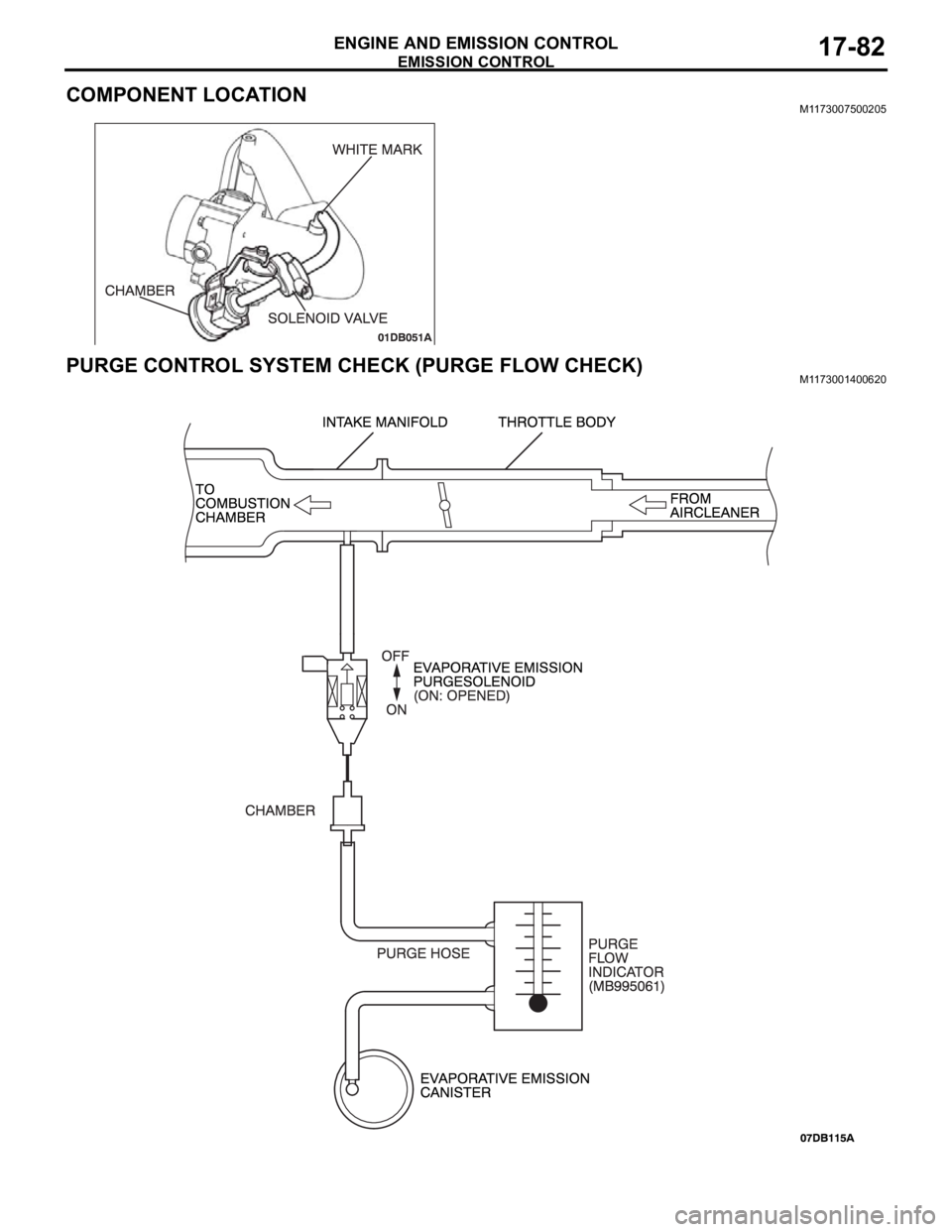
COMPONENT LOCATIONM1173007500205
PURGE CONTROL SYSTEM CHECK (PURGE FLOW CHECK)M1173001400620
Page 1414 of 1500
EMISSION CONTROL
ENGINE AND EMISSION CONTROL17-83
Required Special Tool:
MB995061: Purge Flow Indicator
1. Disconnect the purge hose from the evaporative emission
(EVAP) purge solenoid, and connect special tool MB995061
between the EVAP purge solenoid and the purge hose.
2. Before inspection, set the vehicle in the following conditions:
Engine coolant temperature: 80 95C (176 203F)
Lights, electric cooling fan and accessories: OFF
Transaxle: P range
3. Run the engine at idle for more than four minutes.
4. Check the purge flow volume when engine is revved
suddenly several times.
Standard value: Momentarily 20 cm
3/s (2.5 SCFH) or
more.
5. If the purge flow volume is less than the standard value,
check it again with the vacuum hose disconnected from the
EVAP canister. If the purge flow volume is less than the
standard value, check the vacuum port and the vacuum
hose for clogging. Also check the EVAP purge solenoid. If
the purge flow volume is at the standard value, replace the
EVAP canister.
EVAPORATIVE EMISSION PURGE SOLENOID
CHECK
M1173001700289
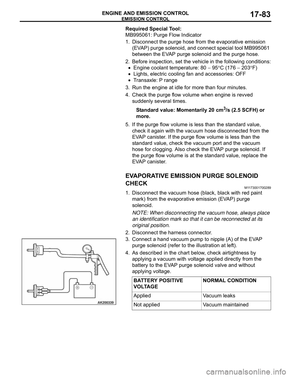
1. Disconnect the vacuum hose (black, black with red paint
mark) from the evaporative emission (EVAP) purge
solenoid.
NOTE: When disconnecting the vacuum hose, always place
an identification mark so that it can be reconnected at its
original position.
2. Disconnect the harness connector.
3. Connect a hand vacuum pump to nipple (A) of the EVAP
purge solenoid (refer to the illustration at left).
4. As described in the chart below, check airtightness by
applying a vacuum with voltage applied directly from the
battery to the EVAP purge solenoid valve and without
applying voltage.
BATTERY POSITIVE
VOLTAGENORMAL CONDITION
Applied Vacuum leaks
Not applied Vacuum maintained
Page 1415 of 1500
![MITSUBISHI 380 2005 Workshop Manual EMISSION CONTROL
ENGINE AND EMISSION CONTROL17-84
5. Measure the resistance between the terminals of the EVAP
purge solenoid.
Standard value: 16
[at 20C )]
6. Replace the solenoid if resistance is MITSUBISHI 380 2005 Workshop Manual EMISSION CONTROL
ENGINE AND EMISSION CONTROL17-84
5. Measure the resistance between the terminals of the EVAP
purge solenoid.
Standard value: 16
[at 20C )]
6. Replace the solenoid if resistance is](/img/19/57086/w960_57086-1414.png)
EMISSION CONTROL
ENGINE AND EMISSION CONTROL17-84
5. Measure the resistance between the terminals of the EVAP
purge solenoid.
Standard value: 16
[at 20C )]
6. Replace the solenoid if resistance is out of specification.
MASS AIRFLOW SENSOR CHECKM1173050400053
To inspect these parts, refer to GROUP 13A, Multipoint Fuel
Injection (MPI)
Multipoint Fuel Injection (MPI) Diagnosis
Diagnostic Trouble Code Chart 13A-17.
ENGINE COOLANT TEMPERATURE SENSOR
CHECK
M1173008100523
To inspect the sensor, refer to GROUP 13A, Multipoint Fuel
Injection (MPI)
Multipoint Fuel Injection (MPI) Diagnosis
Diagnostic Trouble Code Chart 13A-17.
INTAKE AIR TEMPERATURE SENSOR CHECKM1173008200263
To inspect the sensor, refer to GROUP 13A, Multipoint Fuel
Injection (MPI)
Multipoint Fuel Injection (MPI) Diagnosis
Diagnostic Trouble Code Chart 13A-17.
CATALYTIC CONVERTER
GENERAL DESCRIPTION (CATALYTIC CONVERTER)M1173005300131
The three way catalytic converter, together with the
closed loop air-fuel ratio control based on the oxygen
sensor signal, oxidizes carbon monoxides (CO) and
hydrocarbons (HC), also reduces nitrogen oxides
(NOx). When the mixture is controlled at stoichiometric
air-fuel ratio, the three way catalytic converter pro-
vides the highest purification against the three con-
stituents, namely, CO, HC and NOx.
Page 1416 of 1500

SPECIFICATIONS
ENGINE AND EMISSION CONTROL17-85
SPECIFICATIONS
FASTENER TIGHTENING SPECIFICATIONSM1173006400324
SERVICE SPECIFICATIONSM1173000300545
ITEM SPECIFICATION
Auto-cruise control system
Lower cover cap bolt 9.0
2.0 Nm (80 17 in-lb)
Steering wheel assembly nut 41
8 Nm (30 6 ft-lb)
Engine control system
Accelerator pedal assembly nut 13
2 Nm ( 111 22 in-lb)
ITEMSSTANDARD VALUE
Engine control system
Curb idle speed r/min 3.8L Engine 680
100
Emission control system
Purge flow cm
3/s (SCFH) [at 80 95C (176 205F) with sudden revving]20 (2.5)
Evaporative emission purge solenoid coil resistance [at 20
C)] 16