belt MITSUBISHI 380 2005 Repair Manual
[x] Cancel search | Manufacturer: MITSUBISHI, Model Year: 2005, Model line: 380, Model: MITSUBISHI 380 2005Pages: 1500, PDF Size: 47.87 MB
Page 1223 of 1500
GENERAL00-2
MAINTENANCE SERVICE . . . . . . . .00-37
1. FUEL SYSTEM (TANK, PIPE LINE AND
CONNECTION, AND FUEL TANK FILLER
TUBE CAP) (CHECK FOR LEAKS) . . . . . . 00-37
2. FUEL HOSES (CHECK CONDITION) . . 00-37
3. AIR CLEANER FILTER (REPLACE). . . . 00-37
4. EVAPORATIVE EMISSION SYSTEM
(EXCEPT EVAPORATIVE EMISSION
CANISTER) (CHECK FOR CLOGGING) . . 00-37
5. SPARK PLUGS (REPLACE). . . . . . . . . . 00-38
7. TIMING BELT (REPLACE) . . . . . . . . . . . 00-38
8. DRIVE BELTS (FOR ALTERNATOR, POWER
STEERING PUMP AND AIR CONDITIONING)
(CHECK) . . . . . . . . . . . . . . . . . . . . . . . . . . . 00-39
9. EXHAUST SYSTEM (CONNECTIONS
PORTION OF MUFFLER, MUFFLER PIPES
AND CONVERTER HEAT SHIELDS) (CHECK
AND SERVICE AS REQUIRED) . . . . . . . . . 00-44
10. ENGINE OIL (CHANGE) . . . . . . . . . . . . 00-4411. ENGINE OIL FILTER (REPLACE) . . . . 00-44
12. TRANSMISSION FLUID . . . . . . . . . . . . 00-45
13. ENGINE COOLANT (CHANGE) . . . . . . 00-47
14. COOLANT HOSES (RADIATOR HOSE,
HEATER HOSE) (INSPECT). . . . . . . . . . . . 00-49
15. DISC BRAKE PADS, ROTORS
(INSPECT FOR WEAR) . . . . . . . . . . . . . . . 00-49
16. BRAKE HOSES (CHECK FOR
DETERIORATION OR LEAKS) . . . . . . . . . . 00-49
17. BALL JOINT AND STEERING LINKAGE
SEALS (INSPECT FOR GREASE LEAKS
AND DAMAGE) . . . . . . . . . . . . . . . . . . . . . . 00-50
18. DRIVE SHAFT BOOTS (INSPECT FOR
GREASE LEAKS AND DAMAGE) . . . . . . . . 00-50
19. SUSPENSION SYSTEM (INSPECT FOR
LOOSENESS AND DAMAGE) . . . . . . . . . . 00-51
20. SRS AIR BAG (INSPECT FOR SRS
SYSTEM). . . . . . . . . . . . . . . . . . . . . . . . . . . 00-51
21. TYRES (ROTATE). . . . . . . . . . . . . . . . . 00-58
Page 1243 of 1500
PRECAUTIONS BEFORE SERVICE
GENERAL00-22
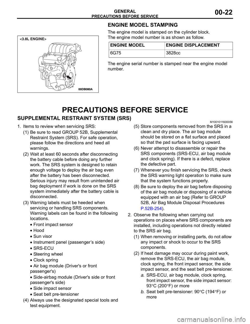
ENGINE MODEL STAMPING
The engine model is stamped on the cylinder block.
The engine model number is as shown as follow.
The engine serial number is stamped near the engine model
number.
PRECAUTIONS BEFORE SERVICE
SUPPLEMENTAL RESTRAINT SYSTEM (SRS)M1001011600056
1. Items to review when servicing SRS:
(1) Be sure to read GROUP 52B, Supplemental
Restraint System (SRS). For safe operation,
please follow the directions and heed all
warnings.
(2) Wait at least 60 seconds after disconnecting
the battery cable before doing any further
work. The SRS system is designed to retain
enough voltage to deploy the air bag even
after the battery has been disconnected.
Serious injury may result from unintended air
bag deployment if work is done on the SRS
system immediately after the battery cable is
disconnected.
(3) Warning labels must be heeded when
servicing or handling SRS components.
Warning labels can be found in the following
locations.
Front impact sensor
Hood
Sun visor
Instrument panel (passenger ’s side)
SRS-ECU
Steering wheel
Clock spring
Air bag module (Driver's or front
passenger's)
Side-airbag module (Driver's side or front
passenger's side)
Side impact sensor
Seat belt pre-tensioner
(4) Always use the designated special tools and
test equipment.(5) Store components removed from the SRS in a
clean and dry place. The air bag module
should be stored on a flat surface and placed
so that the pad surface is facing upward.
(6) Never attempt to disassemble or repair the
SRS components (SRS-ECU, air bag module
and clock spring). If there is a defect, replace
the defective part.
(7) Whenever you finish servicing the SRS, check
the SRS warning light operation to make sure
that the system functions properly.
(8) Be sure to deploy the air bag before disposing
of the air bag module or disposing of a vehicle
equipped with an air bag (Refer to GROUP
52B, Air Bag Module Disposal Procedures
P.52B-254).
2. Observe the following when carrying out
operations on places where SRS components are
installed, including operations not directly related
to the SRS air bag.
(1) When removing or installing parts, do not allow
any impact or shock to occur to the SRS
components.
(2) If heat damage may occur during paint work,
remove the SRS-ECU, the air bag module,
clock spring, the front impact sensor, the side
impact sensor, and the seat belt pre-tensioner.
a.SRS-ECU, air bag module, clock spring,
front impact sensor, the side impact sensor:
93
C (200F) or more
b.Seat belt pre-tensioner: 90
C (194F) or
more ENGINE MODEL ENGINE DISPLACEMENT
6G75 3828cc
Page 1259 of 1500
MAINTENANCE SERVICE
GENERAL00-38
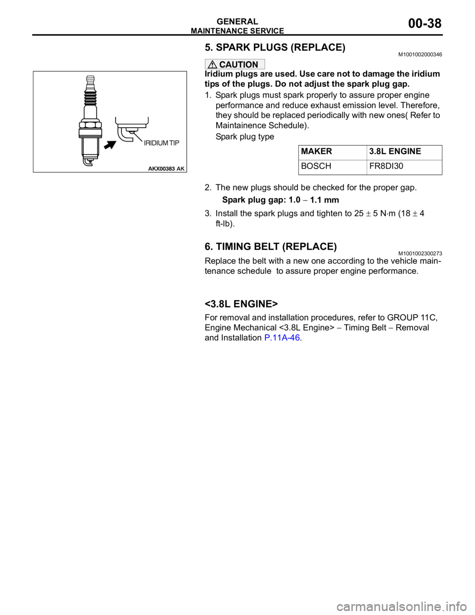
5. SPARK PLUGS (REPLACE)M1001002000346
Iridium plugs are used. Use care not to damage the iridium
tips of the plugs. Do not adjust the spark plug gap.
1. Spark plugs must spark properly to assure proper engine
performance and reduce exhaust emission level. Therefore,
they should be replaced periodically with new ones( Refer to
Maintainence Schedule).
Spark plug type
2. The new plugs should be checked for the proper gap.
Spark plug gap: 1.0
1.1 mm
3. Install the spark plugs and tighten to 25
5 Nm (18 4
ft-lb).
6. TIMING BELT (REPLACE)M1001002300273
Replace the belt with a new one according to the vehicle main-
tenance schedule to assure proper engine performance.
<3.8L ENGINE>
For removal and installation procedures, refer to GROUP 11C,
Engine Mechanical <3.8L Engine>
Timing Belt Removal
and Installation P.11A-46.MAKER 3.8L ENGINE
BOSCH FR8DI30
Page 1260 of 1500
MAINTENANCE SERVICE
GENERAL00-39
7. DRIVE BELTS (FOR ALTERNATOR, POWER
STEERING PUMP AND AIR CONDITIONING)
(CHECK)
M1001008700031
ALTERNATOR DRIVE BELT TENSION CHECK
<3.8L ENGINE>
.
WHEN USING DIAGNOSTIC TOOL (MUT-III)
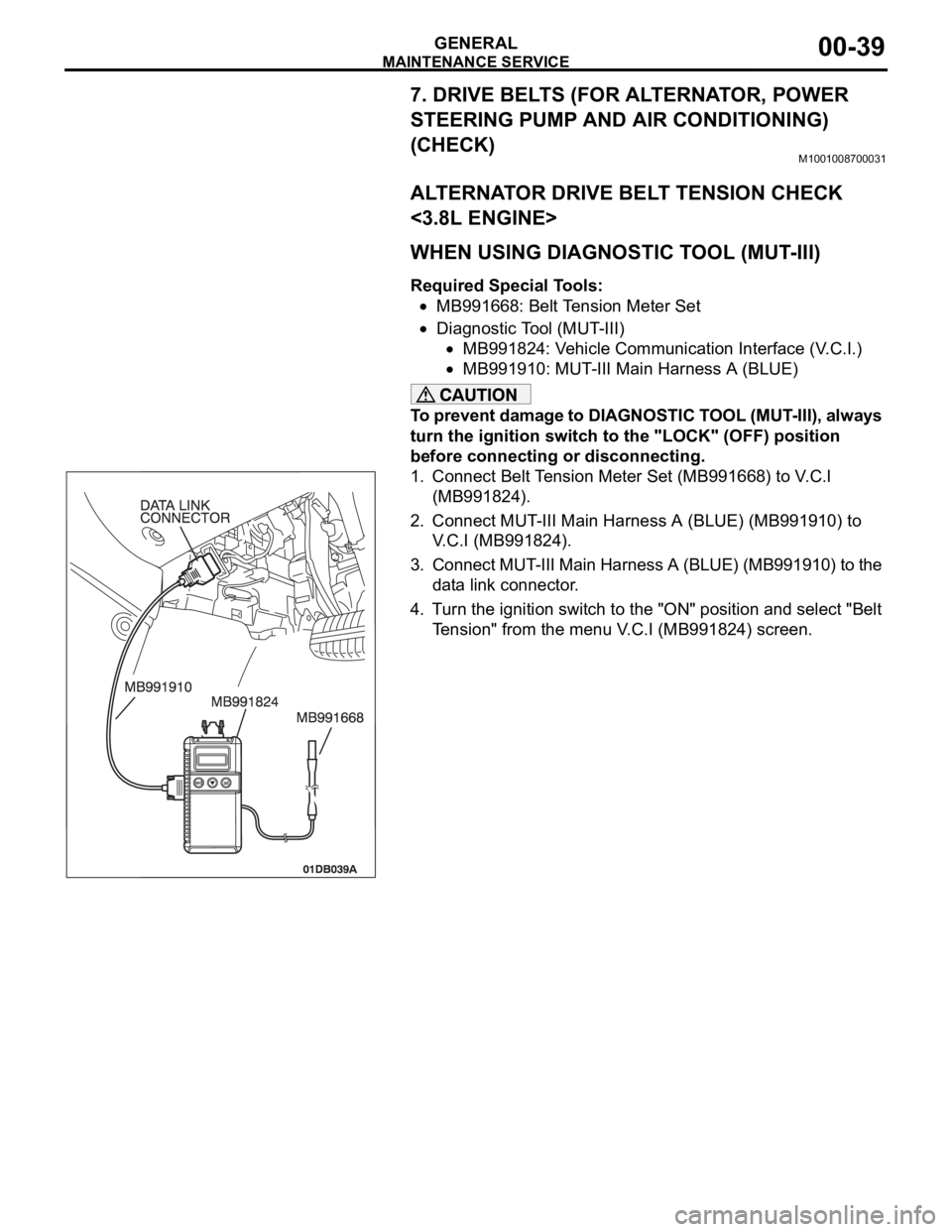
Required Special Tools:
MB991668: Belt Tension Meter Set
Diagnostic Tool (MUT-III)
MB991824: Vehicle Communication Interface (V.C.I.)
MB991910: MUT-III Main Harness A (BLUE)
To prevent damage to DIAGNOSTIC TOOL (MUT-III), always
turn the ignition switch to the "LOCK" (OFF) position
before connecting or disconnecting.
1. Connect Belt Tension Meter Set (MB991668) to V.C.I
(MB991824).
2. Connect MUT-III Main Harness A (BLUE) (MB991910) to
V.C.I (MB991824).
3. Connect MUT-III Main Harness A (BLUE) (MB991910) to the
data link connector.
4. Turn the ignition switch to the "ON" position and select "Belt
Tension" from the menu V.C.I (MB991824) screen.
Page 1261 of 1500
MAINTENANCE SERVICE
GENERAL00-40
The temperature of the surface of the belt should be as
close as possible to underhood temperature.
Do not let any contaminants such as water or oil get
onto the microphone.
If strong gusts of wind blow against the microphone or
if there are any loud sources of noise nearby, the val-
ues measured by the microphone may not correspond
to actual values.
If the microphone is touching the belt while the mea-
surement is being made, the values measured by the
microphone may not correspond to actual values.
Do not take the measurement while the vehicle's engine
is running.
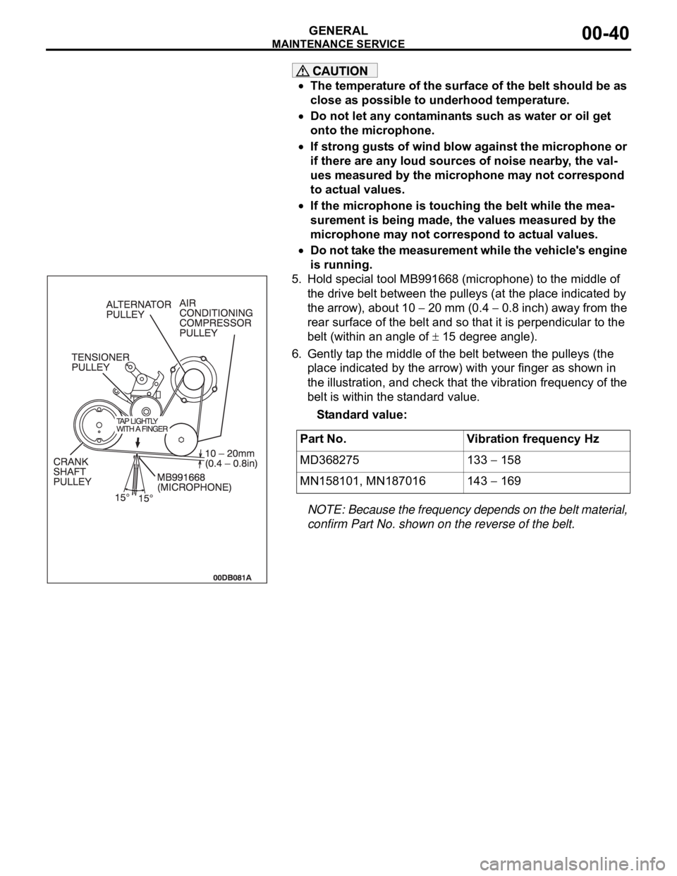
5. Hold special tool MB991668 (microphone) to the middle of
the drive belt between the pulleys (at the place indicated by
the arrow), about 10
20 mm (0.4 0.8 inch) away from the
rear surface of the belt and so that it is perpendicular to the
belt (within an angle of
15 degree angle).
6. Gently tap the middle of the belt between the pulleys (the
place indicated by the arrow) with your finger as shown in
the illustration, and check that the vibration frequency of the
belt is within the standard value.
Standard value:
NOTE: Because the frequency depends on the belt material,
confirm Part No. shown on the reverse of the belt.
.
Part No. Vibration frequency Hz
MD368275 133
158
MN158101, MN187016 143
169
Page 1262 of 1500
MAINTENANCE SERVICE
GENERAL00-41
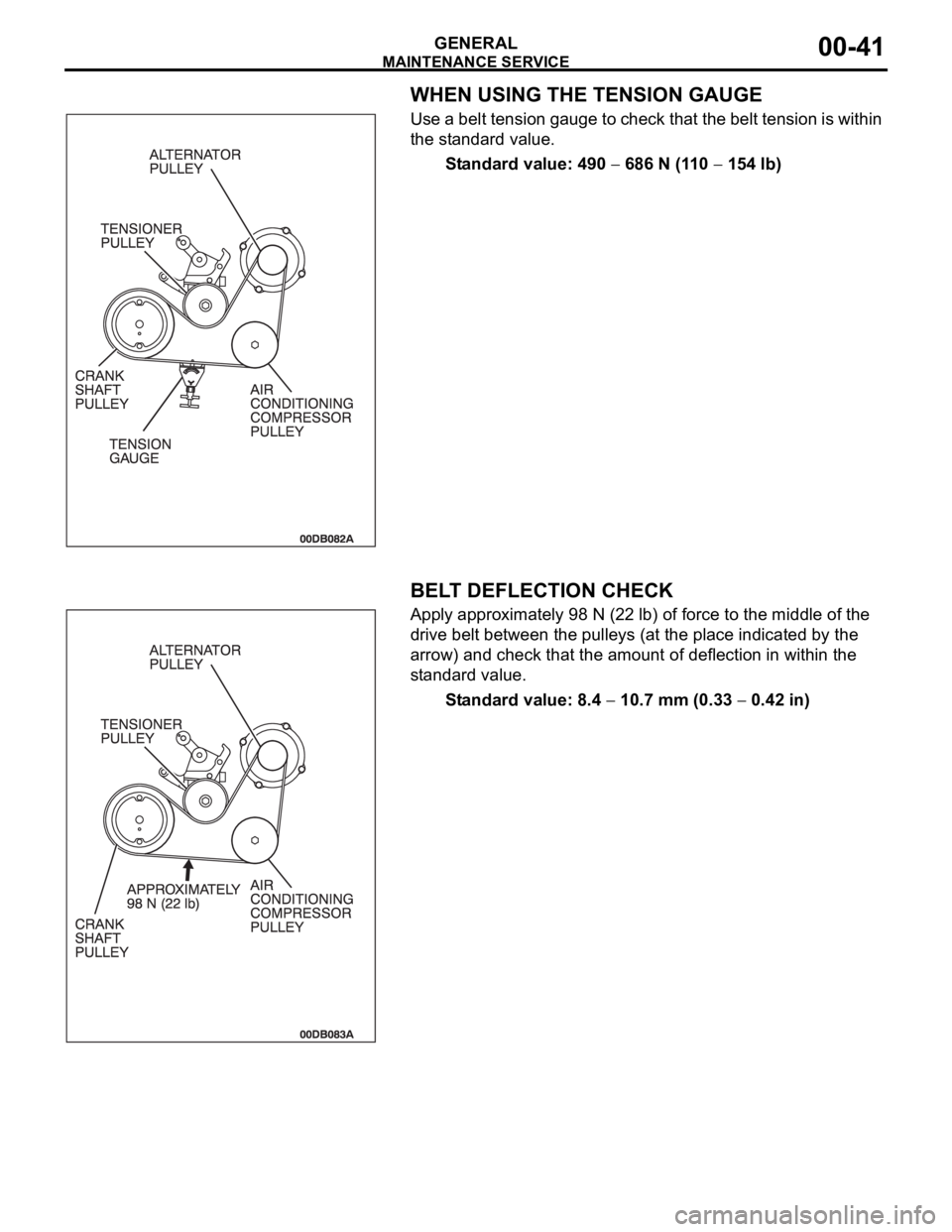
WHEN USING THE TENSION GAUGE
Use a belt tension gauge to check that the belt tension is within
the standard value.
Standard value: 490
686 N (110 154 lb)
.
BELT DEFLECTION CHECK
Apply approximately 98 N (22 lb) of force to the middle of the
drive belt between the pulleys (at the place indicated by the
arrow) and check that the amount of deflection in within the
standard value.
Standard value: 8.4
10.7 mm (0.33 0.42 in)
Page 1263 of 1500

MAINTENANCE SERVICE
GENERAL00-42
ALTERNATOR DRIVE BELT TENSION
ADJUSTMENT
.1. Loosen the tensioner pulley fixing nut.
2. With the tensioner pulley fixing nut temporarily tightened to
15
5 Nm (11 4 ft-lb), set the belt tension or defection
amount to the standard value using the adjusting bolt.
Standard value:
3. Tighten the tension pulley fixing nut.
Tightening torque: 49
10 Nm (36 7 ft-lb)
POWER STEERING DRIVE BELT TENSION
CHECK
.
WHEN USING DIAGNOSTIC TOOL (MUT-III)
Required Special Tools:
MB991668: Belt Tension Meter Set
Diagnostic Tool (MUT-III)
MB991824: Vehicle Communication Interface (V.C.I.)
MB991910: MUT-III Main Harness A (BLUE)
Gently tap the middle of the belt between the pulleys (the loca-
tion indicated by the arrow) with your finger as shown in the
illustration, and check that the vibration frequency of the belt is
within the standard value.
NOTE: Refer to P.00-39 for details on the method of measuring
the vibration frequency using the scan tool.
Standard value:
.
ITEMS DURING
ADJUSTMENTDURING
REPLACEMENT
Vibration
frequency Hz150
163 180 202
Tension N (lb) 539
637
(121
143)785
981
(176
221)
Deflection
(Reference value)
mm (in)8.9
10.1
(0.35
0.40)6.2
7.5
(0.24
0.30)
ITEM WHEN
CHECKEDDURING
ADJUSTME
NTDURING
REPLACEM
ENT
Vibration
frequency Hz124
160 134 151 160 189
Page 1264 of 1500
MAINTENANCE SERVICE
GENERAL00-43
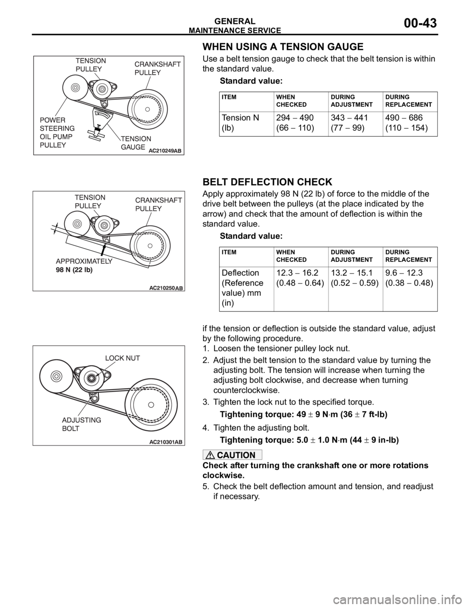
WHEN USING A TENSION GAUGE
Use a belt tension gauge to check that the belt tension is within
the standard value.
Standard value:
.
BELT DEFLECTION CHECK
Apply approximately 98 N (22 lb) of force to the middle of the
drive belt between the pulleys (at the place indicated by the
arrow) and check that the amount of deflection is within the
standard value.
Standard value:
.if the tension or deflection is outside the standard value, adjust
by the following procedure.
1. Loosen the tensioner pulley lock nut.
2. Adjust the belt tension to the standard value by turning the
adjusting bolt. The tension will increase when turning the
adjusting bolt clockwise, and decrease when turning
counterclockwise.
3. Tighten the lock nut to the specified torque.
Tightening torque: 49
9 Nm (36 7 ft-lb)
4. Tighten the adjusting bolt.
Tightening torque: 5.0
1.0 Nm (44 9 in-lb)
Check after turning the crankshaft one or more rotations
clockwise.
5. Check the belt deflection amount and tension, and readjust
if necessary.
ITEM WHEN
CHECKEDDURING
ADJUSTMENTDURING
REPLACEMENT
Te n s i o n N
(lb)294 490
(66
110)343
441
(77
99)490
686
(110
154)
ITEM WHEN
CHECKEDDURING
ADJUSTMENTDURING
REPLACEMENT
Deflection
(Reference
value) mm
(in)12.3 16.2
(0.48
0.64)13.2
15.1
(0.52
0.59)9.6
12.3
(0.38
0.48)
Page 1272 of 1500
MAINTENANCE SERVICE
GENERAL00-51
18. SUSPENSION SYSTEM (INSPECT FOR
LOOSENESS AND DAMAGE)
M1001009600048
Visually inspect the front/rear suspension components for dete-
rioration and damage. Re-tighten the front/rear suspension
components retaining bolts to specified torque.
19. SRS AIR BAG (INSPECT FOR SRS SYSTEM)M1001003700326
The entire SRS including air bag and pre-tensioner seat belt
must be inspected by an authorized MITSUBISHI MOTORS
dealer 10 years.
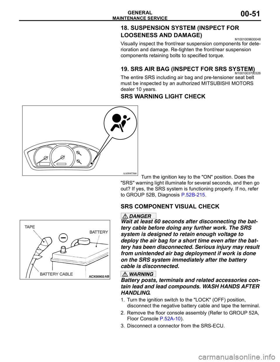
SRS WARNING LIGHT CHECK
Turn the ignition key to the "ON" position. Does the
"SRS" warning light illuminate for several seconds, and then go
out? If yes, the SRS system is functioning properly. If no, refer
to GROUP 52B, Diagnosis P.52B-215.
SRS COMPONENT VISUAL CHECK
Wait at least 60 seconds after disconnecting the bat-
tery cable before doing any further work. The SRS
system is designed to retain enough voltage to
deploy the air bag for a short time even after the bat-
tery has been disconnected. Serious injury may result
from unintended air bag deployment if work is done
on the SRS system immediately after the battery
cable is disconnected.
Battery posts, terminals and related accessories con-
tain lead and lead compounds. WASH HANDS AFTER
HANDLING.
1. Turn the ignition switch to the "LOCK" (OFF) position,
disconnect the negative battery cable and tape the terminal.
2. Remove the floor console assembly (Refer to GROUP 52A,
Floor Console P.52A-10).
3. Disconnect a connector from the SRS-ECU.
Page 1276 of 1500
MAINTENANCE SERVICE
GENERAL00-55
The SRS may not activate if any of the above compo-
nents are not installed properly, which could result in
serious injury or death to the vehicle's driver and
front passenger.
11.Check the steering wheel for excessive free play.
Replace any part if it fails visual inspection (Refer to
GROUP 52B, Air Bag Module and Clock Spring P.52B-237).
FRONT SEATBACK ASSEMBLY WITH
SIDE-AIRBAG MODULE
If any improper part is found during the following
inspection, replace the front seatback assembly
with a new one.
Dispose of the old one according to the specified
procedure (Refer to GROUP 52B, Air Bag Module
Disposal Procedures P.52B-254).
Never attempt to measure the circuit resistance of
the air bag module (squib) even if you are using
the specified tester. If the circuit resistance is mea-
sured with a tester, accidental air bag deployment
will result in serious personal injury.
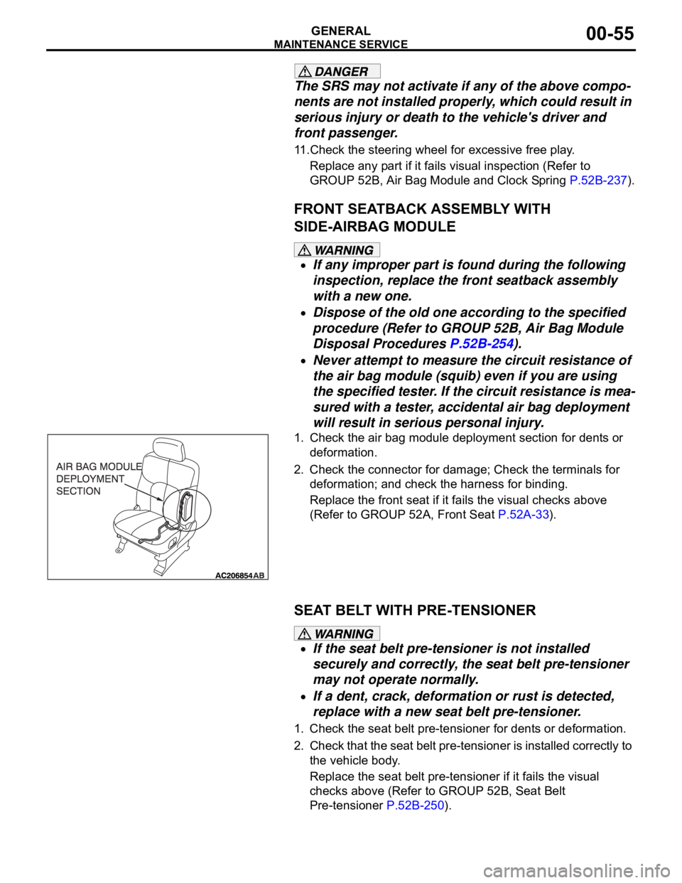
1. Check the air bag module deployment section for dents or
deformation.
2. Check the connector for damage; Check the terminals for
deformation; and check the harness for binding.
Replace the front seat if it fails the visual checks above
(Refer to GROUP 52A, Front Seat P.52A-33).
SEAT BELT WITH PRE-TENSIONER
If the seat belt pre-tensioner is not installed
securely and correctly, the seat belt pre-tensioner
may not operate normally.
If a dent, crack, deformation or rust is detected,
replace with a new seat belt pre-tensioner.
1. Check the seat belt pre-tensioner for dents or deformation.
2. Check that the seat belt pre-tensioner is installed correctly to
the vehicle body.
Replace the seat belt pre-tensioner if it fails the visual
checks above (Refer to GROUP 52B, Seat Belt
Pre-tensioner P.52B-250).