warning MITSUBISHI 380 2005 Repair Manual
[x] Cancel search | Manufacturer: MITSUBISHI, Model Year: 2005, Model line: 380, Model: MITSUBISHI 380 2005Pages: 1500, PDF Size: 47.87 MB
Page 1272 of 1500

MAINTENANCE SERVICE
GENERAL00-51
18. SUSPENSION SYSTEM (INSPECT FOR
LOOSENESS AND DAMAGE)
M1001009600048
Visually inspect the front/rear suspension components for dete-
rioration and damage. Re-tighten the front/rear suspension
components retaining bolts to specified torque.
19. SRS AIR BAG (INSPECT FOR SRS SYSTEM)M1001003700326
The entire SRS including air bag and pre-tensioner seat belt
must be inspected by an authorized MITSUBISHI MOTORS
dealer 10 years.
SRS WARNING LIGHT CHECK
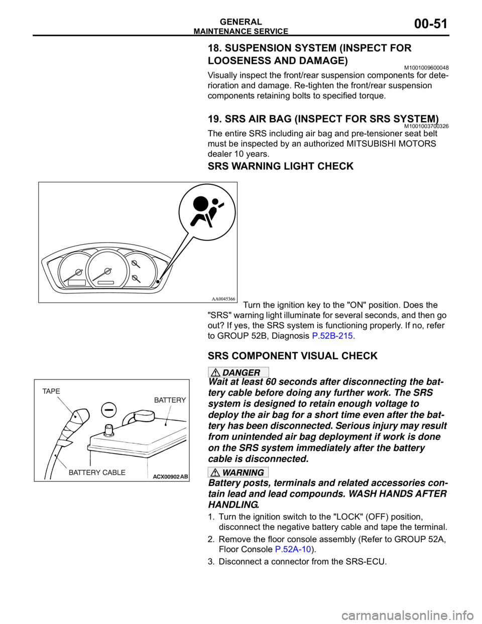
Turn the ignition key to the "ON" position. Does the
"SRS" warning light illuminate for several seconds, and then go
out? If yes, the SRS system is functioning properly. If no, refer
to GROUP 52B, Diagnosis P.52B-215.
SRS COMPONENT VISUAL CHECK
Wait at least 60 seconds after disconnecting the bat-
tery cable before doing any further work. The SRS
system is designed to retain enough voltage to
deploy the air bag for a short time even after the bat-
tery has been disconnected. Serious injury may result
from unintended air bag deployment if work is done
on the SRS system immediately after the battery
cable is disconnected.
Battery posts, terminals and related accessories con-
tain lead and lead compounds. WASH HANDS AFTER
HANDLING.
1. Turn the ignition switch to the "LOCK" (OFF) position,
disconnect the negative battery cable and tape the terminal.
2. Remove the floor console assembly (Refer to GROUP 52A,
Floor Console P.52A-10).
3. Disconnect a connector from the SRS-ECU.
Page 1281 of 1500

GENERAL DESCRIPTION
TRACTION CONTROL SYSTEM (TCL)13C-2
GENERAL DESCRIPTIONM1136000100029
Traction Control systems are a significant safety fea-
ture designed to prevent wheel spin during accelera-
tion. This results in improved vehicle stability and
steer ability. When excessive wheel spin is detected,
the system will automatically reduce engine torque
via the engine management system. The Engine
ECU can reduce throttle position, cut fuel injection
and retard ignition to one or more cylinders depend-ing on how much torque reduction is required and
will continue to occur until the wheels are no longer
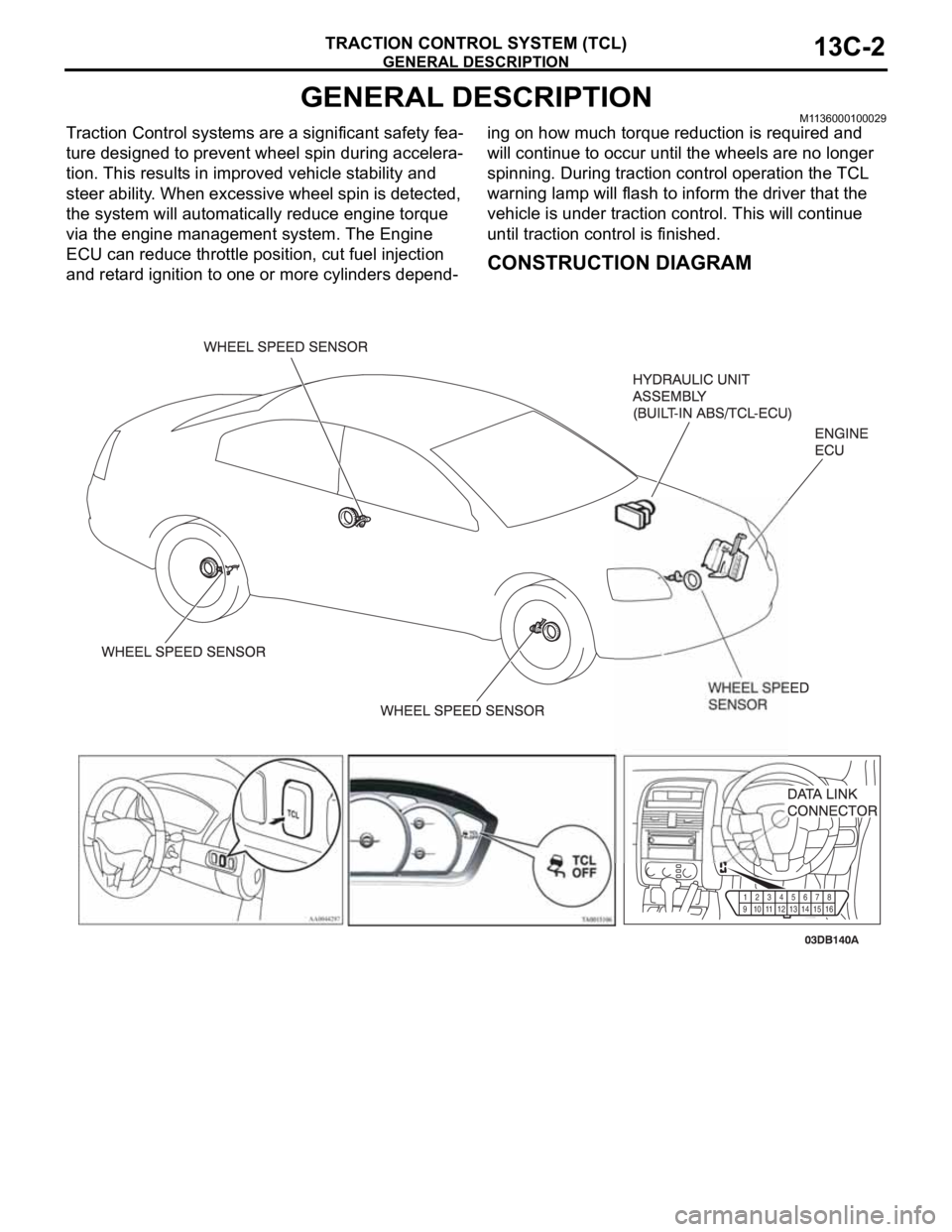
spinning. During traction control operation the TCL
warning lamp will flash to inform the driver that the
vehicle is under traction control. This will continue
until traction control is finished.
CONSTRUCTION DIAGRAM
91011
1213141516 12345
678
Page 1460 of 1500

23A-1
GROUP 23A
AUTOMATIC
TRANSMISSION
CONTENTS
GENERAL DESCRIPTION. . . . . . . . .23A-3
AUTOMATIC TRANSMISSION
DIAGNOSIS . . . . . . . . . . . . . . . . . . . .23A-12
DIAGNOSTIC TROUBLESHOOTING FLOW23A-12
INTRODUCTION TO A/T DIAGNOSIS . . . . 23A-12
A/T DIAGNOSTIC TROUBLESHOOTING
STRATEGY . . . . . . . . . . . . . . . . . . . . . . . . . 23A-13
DIAGNOSTIC FUNCTION . . . . . . . . . . . . . 23A-13
HOW TO INITIALIZE A/T LEARNING
VALUE . . . . . . . . . . . . . . . . . . . . . . . . . . . . 23A-17
FAIL-SAFE/BACKUP FUNCTION. . . . . . . . 23A-18
ROAD TEST . . . . . . . . . . . . . . . . . . . . . . . . 23A-19
TORQUE CONVERTER STALL TEST . . . . 23A-25
HYDRAULIC PRESSURE TESTS . . . . . . . 23A-26
HYDRAULIC CIRCUIT . . . . . . . . . . . . . . . . 23A-32LINE PRESSURE ADJUSTMENT . . . . . . . . 23A-33
DIAGNOSTIC TROUBLE CODE CHART . . 23A-34
SYMPTOM CHART . . . . . . . . . . . . . . . . . . . 23A-35
DIAGNOSTIC TROUBLE CODE
PROCEDURES . . . . . . . . . . . . . . . . . . . . . . 23A-36
SYMPTOM PROCEDURES . . . . . . . . . . . . 23A-218
DATA LIST REFERENCE TABLE . . . . . . . . 23A-271
ACTUATOR TEST REFERENCE TABLE . . 23A-276
A/T-ECU TERMINAL VOLTAGE REFERENCE
CHART FOR TRANSMISSION OPERATION23A-278
A/T-ECU TERMINAL RESISTANCE AND
CONTINUITY INSPECTION CHART . . . . . 23A-284
INSPECTION PROCEDURE USING AN
OSCILLOSCOPE . . . . . . . . . . . . . . . . . . . . 23A-285
Continued on next page
WARNINGS REGARDING SERVICING OF SUPPLEMENTAL RESTRAINT SYSTEM (SRS) EQUIPPED VEHICLES
Page 1472 of 1500

AUTOMATIC TRANSMISSION DIAGNOSIS
AUTOMATIC TRANSMISSION23A-13
A/T DIAGNOSTIC TROUBLESHOOTING STRATEGYM1231007600339
Use these steps to plan your diagnostic strategy. If
you follow them carefully, you will find most A/T mal-
functions.
1. Gather as much information as possible about the
complaint from the customer.
2. Verify that the condition described by the
customer exists.
3. Check the vehicle for any A/T Diagnostic Trouble
Codes (DTCs).
4. If you can not verify the condition and there are no
DTCs, the malfunction is intermittent. For
information on how to cope with intermittent
malfunctions, refer to GROUP 00, How to Use
Troubleshooting/Inspection Service Points
How
to Cope with Intermittent Malfunction P.00-14.
5. If you can verify the condition but there are no
DTCs, or the system can not communicate with
diagnostic tool, refer to the Symptom Chart
P.23A-35.6. If there is a DTC, record the number of the code,
then erase the code from memory using
diagnostic tool.
7. Reconfirm the symptom with a Road Test.
8. If a DTC is set again, go to the Inspection Chart
for Diagnostic Trouble Codes.
9. If a DTC is not set again, the malfunction is
intermittent. For information on how to cope with
intermittent malfunctions, refer to GROUP 00,
How to Use Troubleshooting/Inspection Service
Points
How to Cope with Intermittent
Malfunction P.00-14.
10.After repairs are completed, conduct a Road Test
duplicating the complaint conditions to confirm the
malfunction has been eliminated.
DIAGNOSTIC FUNCTIONM1231022500135
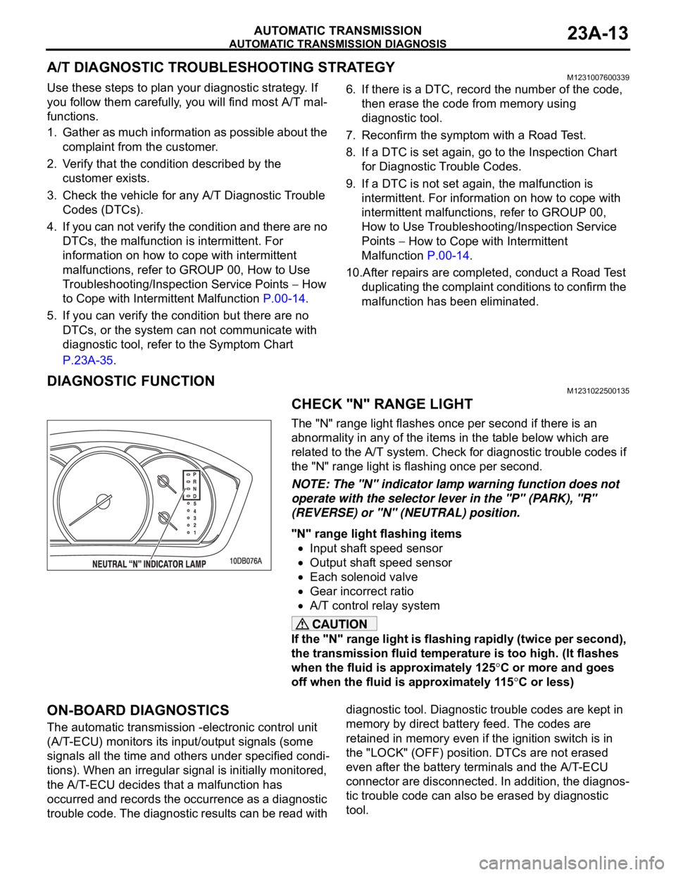
CHECK "N" RANGE LIGHT
The "N" range light flashes once per second if there is an
abnormality in any of the items in the table below which are
related to the A/T system. Check for diagnostic trouble codes if
the "N" range light is flashing once per second.
NOTE: The "N" indicator lamp warning function does not
operate with the selector lever in the "P" (PARK), "R"
(REVERSE) or "N" (NEUTRAL) position.
"N" range light flashing items
Input shaft speed sensor
Output shaft speed sensor
Each solenoid valve
Gear incorrect ratio
A/T control relay system
If the "N" range light is flashing rapidly (twice per second),
the transmission fluid temperature is too high. (It flashes
when the fluid is approximately 125
C or more and goes
off when the fluid is approximately 115
C or less)
ON-BOARD DIAGNOSTICS
The automatic transmission -electronic control unit
(A/T-ECU) monitors its input/output signals (some
signals all the time and others under specified condi-
tions). When an irregular signal is initially monitored,
the A/T-ECU decides that a malfunction has
occurred and records the occurrence as a diagnostic
trouble code. The diagnostic results can be read with diagnostic tool. Diagnostic trouble codes are kept in
memory by direct battery feed. The codes are
retained in memory even if the ignition switch is in
the "LOCK" (OFF) position. DTCs are not erased
even after the battery terminals and the A/T-ECU
connector are disconnected. In addition, the diagnos-
tic trouble code can also be erased by diagnostic
tool.