warning MITSUBISHI 380 2005 Repair Manual
[x] Cancel search | Manufacturer: MITSUBISHI, Model Year: 2005, Model line: 380, Model: MITSUBISHI 380 2005Pages: 1500, PDF Size: 47.87 MB
Page 690 of 1500
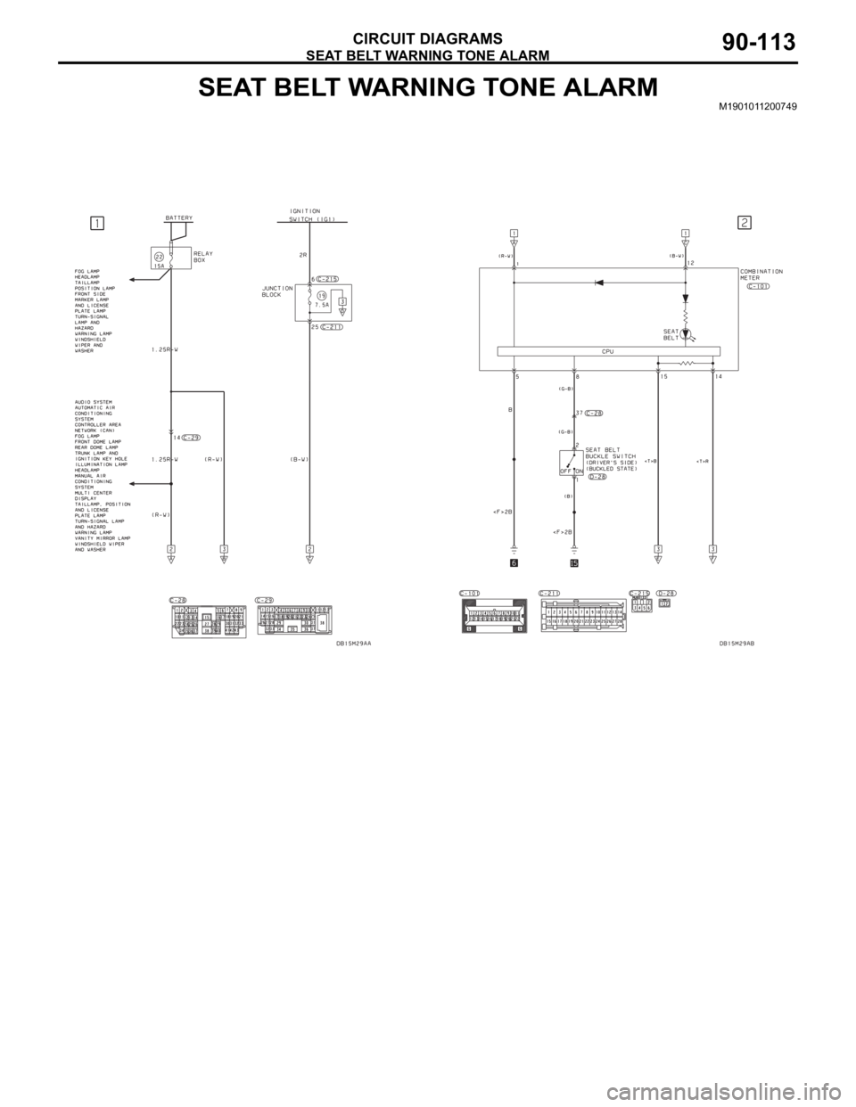
SEAT BELT WARNING TONE ALARM
CIRCUIT DIAGRAMS90-113
SEAT BELT WARNING TONE ALARMM1901011200749
Page 691 of 1500
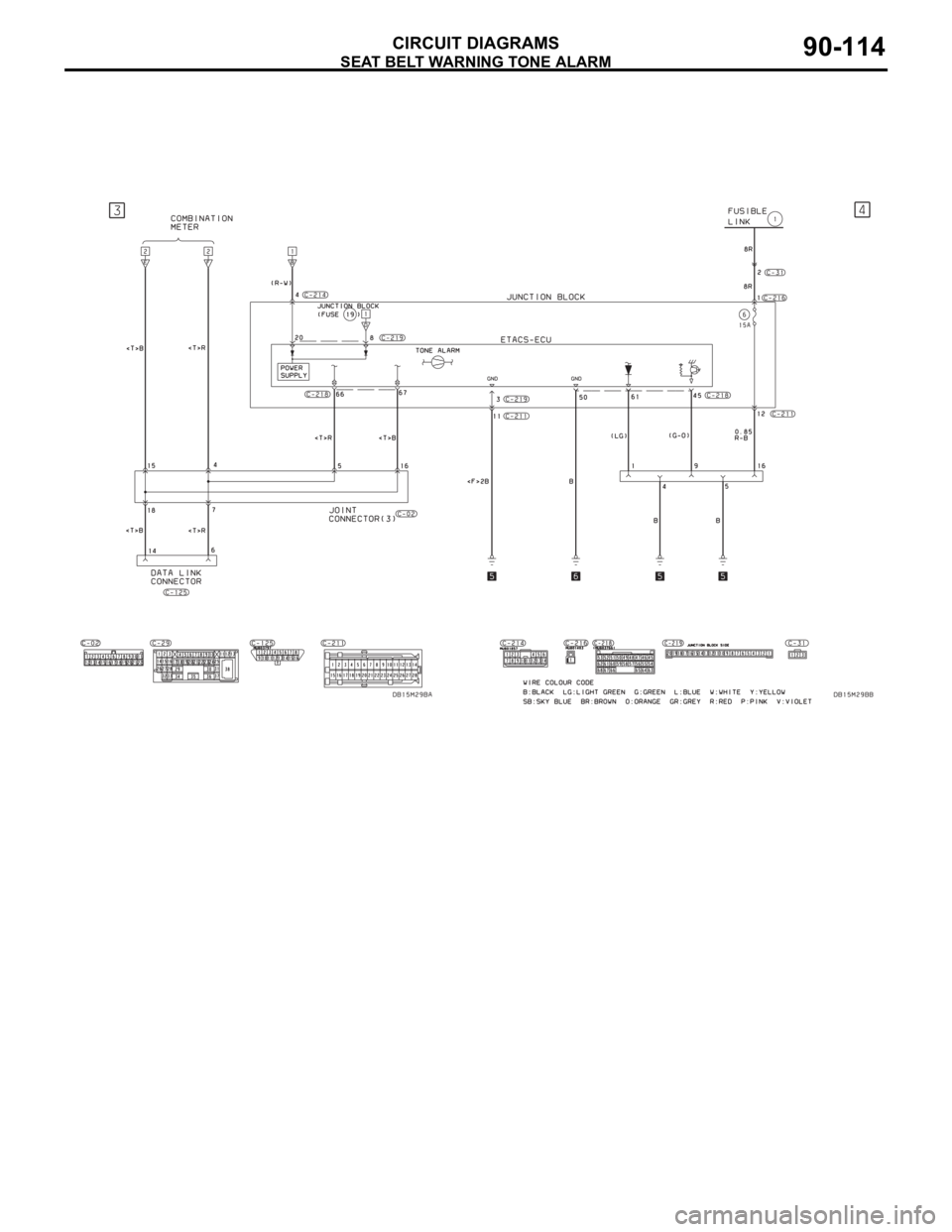
SEAT BELT WARNING TONE ALARM
CIRCUIT DIAGRAMS90-114
Page 692 of 1500
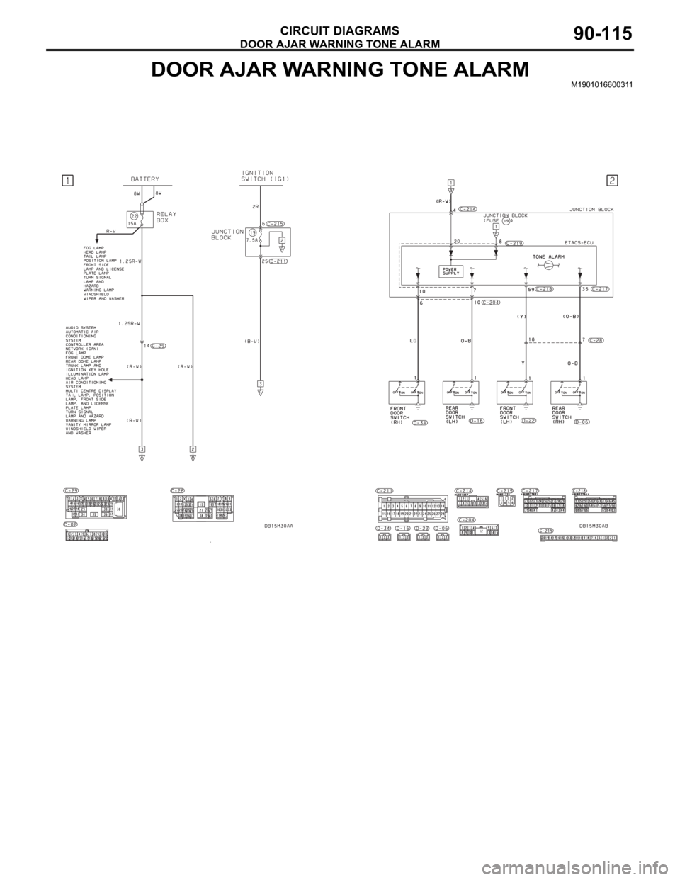
DOOR AJAR WARNING TONE ALARM
CIRCUIT DIAGRAMS90-115
DOOR AJAR WARNING TONE ALARMM1901016600311
Page 693 of 1500
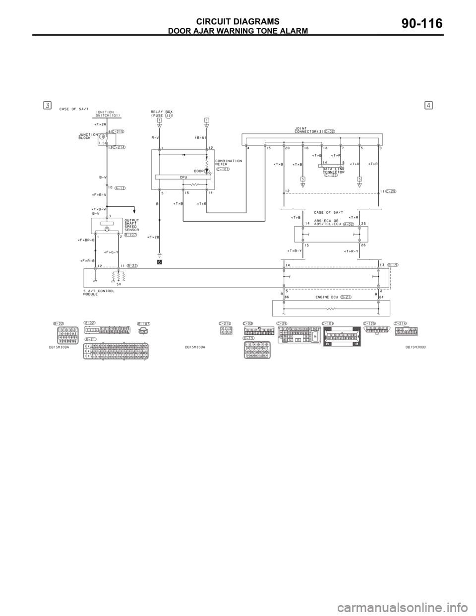
DOOR AJAR WARNING TONE ALARM
CIRCUIT DIAGRAMS90-116
Page 694 of 1500
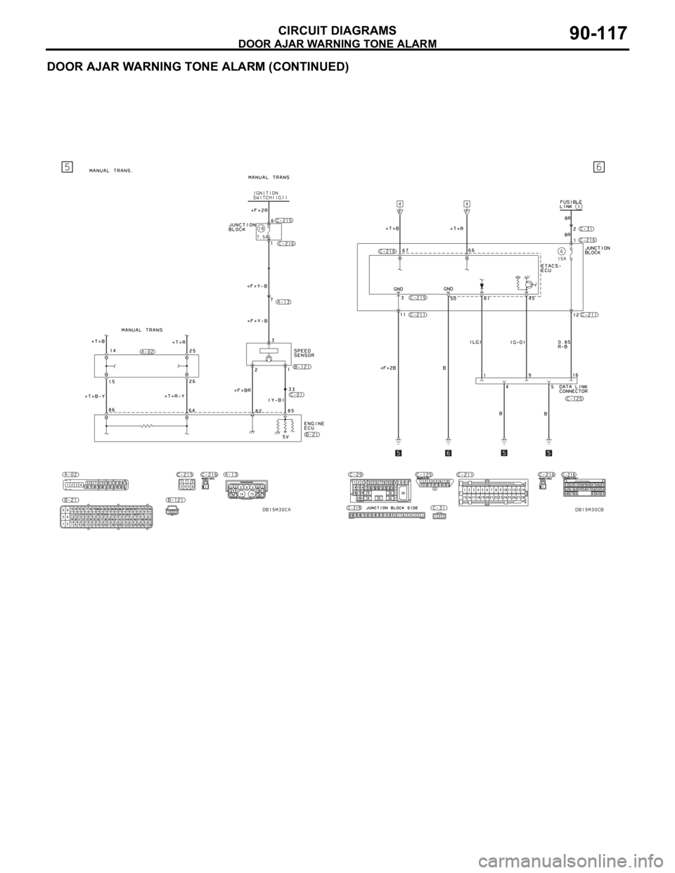
DOOR AJAR WARNING TONE ALARM
CIRCUIT DIAGRAMS90-117
DOOR AJAR WARNING TONE ALARM (CONTINUED)
Page 1134 of 1500

KEYLESS ENTRY SYSTEM
BODY42-67
KEYLESS ENTRY SYSTEM
GENERAL DESCRIPTIONBGBJABIE
Antenna and receiver are incorporated in the
ETACS-ECU.
ID code can be registered by using Diagnostic
tool (MUT-III).
Transmitter is a key holder type, which incorpo-
rates lock button, unlock button, trunk button and
panic button
When the transmitter unlock button is pressed
once, the driver's door will be unlocked. If the but-
ton is pressed twice, all the doors will be
unlocked. The adjustment function also allows
you to open all the doors by pressing the unlock
button only once. For further details on using the
multi-center display to adjust the unlock opera-
tion, refer to GROUP 54B, On-vehicle Service
P.54B-486.
When the transmitter is operated, the answer-
back function will work as follows:
The answerback operation can be altered as fol-
lows:NOTE: Enabling/disabling the hazard warning
light flashing, the horn sounding in accordance
with the answerback function. For further details
on using the transmitter to adjust answerback,
P.42-72 see the section below. For further details
on using the multi-center display to adjust
answerback, refer to GROUP 54B, On-vehicle
Service P.54B-486. ITEM OPERATION
DOORS LOCKED DOORS UNLOCKED
Dome light Flashes once Illuminates for 15 seconds
Turn-signal lights (RH and LH) Flashes once Flashes twice
Horn Sounds once when the lock button
is pressed with all the doors locked-
ITEM ADJUSTMENT ITEM ADJUSTMENT DETAIL
Keyless entry system
confirmation by turn
signal lightsAdjustment of hazard answerback
when the transmitter is used to
lock doorsWhen adjusting hazard answerback after the
doors are locked with the transmitter, the
following flashing conditions can be selected.
a. Flash (default)
b. No flash
Adjustment of hazard answerback
when the transmitter is used to
unlock doorsWhen adjusting hazard answerback after the
doors are unlocked with the transmitter, the
following flashing conditions can be selected.
a. Flash (default)
b. No flash
Keyless entry system
confirmation by hornAdjustment of horn answerback
when the transmitter is used to
lock doorsWhen adjusting horn answerback after the
doors are locked with the transmitter, the
following horn conditions can be selected.
a. Horn sounds
b. Horn sounds if doors are already locked
(default)
c. Horn does not sound
Page 1141 of 1500
KEYLESS ENTRY SYSTEM
BODY42-74
To prevent damage to special tool MB991824 (V.C.I.),
always turn the ignition switch to “LOCK” (OFF) position
before connecting or disconnecting special tool MB991824
(V.C.I.).
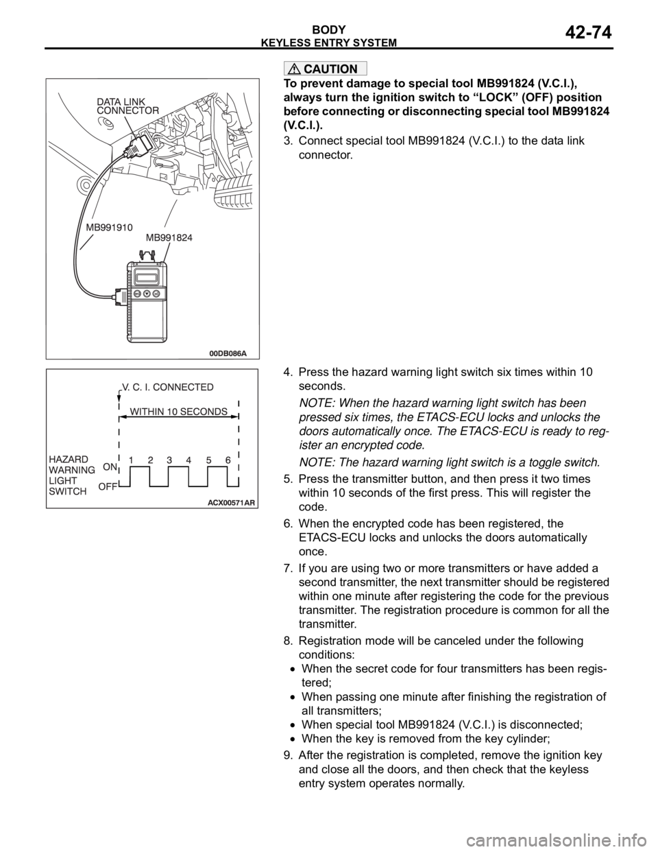
3. Connect special tool MB991824 (V.C.I.) to the data link
connector.
4. Press the hazard warning light switch six times within 10
seconds.
NOTE: When the hazard warning light switch has been
pressed six times, the ETACS-ECU locks and unlocks the
doors automatically once. The ETACS-ECU is ready to reg-
ister an encrypted code.
NOTE: The hazard warning light switch is a toggle switch.
5. Press the transmitter button, and then press it two times
within 10 seconds of the first press. This will register the
code.
6. When the encrypted code has been registered, the
ETACS-ECU locks and unlocks the doors automatically
once.
7. If you are using two or more transmitters or have added a
second transmitter, the next transmitter should be registered
within one minute after registering the code for the previous
transmitter. The registration procedure is common for all the
transmitter.
8. Registration mode will be canceled under the following
conditions:
When the secret code for four transmitters has been regis-
tered;
When passing one minute after finishing the registration of
all transmitters;
When special tool MB991824 (V.C.I.) is disconnected;
When the key is removed from the key cylinder;
9. After the registration is completed, remove the ignition key
and close all the doors, and then check that the keyless
entry system operates normally.
Page 1224 of 1500

HOW TO USE THIS MANUAL
GENERAL00-3
HOW TO USE THIS MANUALM1001000100897
MAINTENANCE, REPAIR AND
SERVICING EXPLANATIONS
This manual provides explanations, etc. concerning
procedures for the inspection, maintenance, repair
and servicing of the subject model. Unless otherwise
specified, each service procedure covers all models.
Procedures covering specific models are identified
by the model codes, or similar designation (engine
type, transaxle type, etc). A description of these des-
ignations is covered in this manual under "VEHICLE
IDENTIFICATION."
.
ON-VEHICLE SERVICE
The "ON-VEHICLE SERVICE" section has proce-
dures for performing inspections and adjustments of
particularly important components. These proce-
dures are done with regard to maintenance and ser-
vicing, but other inspections (looseness, play,
cracking, damage, etc.) must also be performed.
.
SERVICE PROCEDURES
The service steps are arranged in numerical order.
Attention to be paid in performing vehicle service are
described in detail in SERVICE POINTS.
DEFINITION OF TERMS
.
STANDARD VALUE
Indicates the value used as the standard for judging
whether or not a part or adjustment is correct.
.
LIMIT
Shows the maximum or minimum value for judging
whether or not a part or adjustment is acceptable.
.
REFERENCE VALUE
Indicates the adjustment value prior to starting the
work (presented in order to facilitate assembly and
adjustment procedures, and so they can be com-
pleted in a shorter time).
.
DANGER, WARNING, AND CAUTION
DANGER, WARNING, and CAUTION call special
attention to a necessary action or to an action that
must be avoided. The differences among DANGER,
WARNING, and CAUTION are as follows:
If a DANGER is not followed, the result is severe
bodily harm or even death.
If a WARNING is not followed, the result could be
bodily injury.
If a CAUTION is not followed, the result could be
damage to the vehicle, vehicle components or
service equipment.
TIGHTENING TORQUE INDICATION
The tightening torque indicates a median and its tol-
erance by a unit of N
m (in-lb.) or Nm (ft.-lb.). For
fasteners with no assigned torque value, refer to
P.00-32.
SPECIAL TOOL NOTE
Only MMC special tool part numbers are called out in
the repair sections of this manual. Please refer to the
special tool cross-reference chart located at the
beginning of each group, for the special tool number
that is available in your market.
ABBREVIATIONS
The following abbreviations are used in this manual
for classification of model types:
A/T:Automatic transaxle, or models equipped with
automatic transaxle.
MPI: Multipoint fuel injection, or engines equipped
with multiport fuel injection.
A/C: Air conditioning.
3.8L engine: 3.8 litre <6G75> engine, or a model
equipped with such an engine.
ABS: Anti-lock Braking System
TCL: Traction Control System
ECU: Electronic Control Unit
V.C.I.: Vehicle Communication Interface
SWS: Simplified Wiring System
CAN: Controller Area Network
M/T: Manual Transmission
SRS: Supplemental Restraint System
Page 1233 of 1500
HOW TO USE TROUBLESHOOTING/INSPECTION SERVICE POINTS
GENERAL00-12
IF INSPECTING WITH THE CONNECTOR
DISCONNECTED
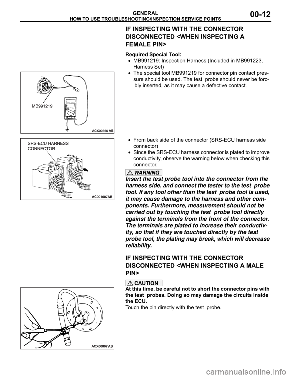
Required Special Tool:
MB991219: Inspection Harness (Included in MB991223,
Harness Set)
The special tool MB991219 for connector pin contact pres-
sure should be used. The test probe should never be forc-
ibly inserted, as it may cause a defective contact.
From back side of the connector (SRS-ECU harness side
connector)
Since the SRS-ECU harness connector is plated to improve
conductivity, observe the warning below when checking this
connector.
Insert the test probe tool into the connector from the
harness side, and connect the tester to the test probe
tool. If any tool other than the test probe tool is used,
it may cause damage to the harness and other com-
ponents. Furthermore, measurement should not be
carried out by touching the test probe tool directly
against the terminals from the front of the connector.
The terminals are plated to increase their conductiv-
ity, so that if they are touched directly by the test
probe tool, the plating may break, which will decrease
reliability.
IF INSPECTING WITH THE CONNECTOR
DISCONNECTED
At this time, be careful not to short the connector pins with
the test probes. Doing so may damage the circuits inside
the ECU.
Touch the pin directly with the test probe.
Page 1243 of 1500
PRECAUTIONS BEFORE SERVICE
GENERAL00-22
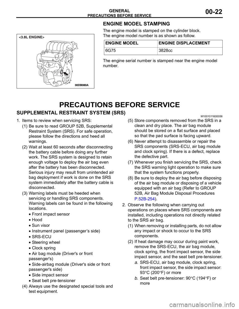
ENGINE MODEL STAMPING
The engine model is stamped on the cylinder block.
The engine model number is as shown as follow.
The engine serial number is stamped near the engine model
number.
PRECAUTIONS BEFORE SERVICE
SUPPLEMENTAL RESTRAINT SYSTEM (SRS)M1001011600056
1. Items to review when servicing SRS:
(1) Be sure to read GROUP 52B, Supplemental
Restraint System (SRS). For safe operation,
please follow the directions and heed all
warnings.
(2) Wait at least 60 seconds after disconnecting
the battery cable before doing any further
work. The SRS system is designed to retain
enough voltage to deploy the air bag even
after the battery has been disconnected.
Serious injury may result from unintended air
bag deployment if work is done on the SRS
system immediately after the battery cable is
disconnected.
(3) Warning labels must be heeded when
servicing or handling SRS components.
Warning labels can be found in the following
locations.
Front impact sensor
Hood
Sun visor
Instrument panel (passenger ’s side)
SRS-ECU
Steering wheel
Clock spring
Air bag module (Driver's or front
passenger's)
Side-airbag module (Driver's side or front
passenger's side)
Side impact sensor
Seat belt pre-tensioner
(4) Always use the designated special tools and
test equipment.(5) Store components removed from the SRS in a
clean and dry place. The air bag module
should be stored on a flat surface and placed
so that the pad surface is facing upward.
(6) Never attempt to disassemble or repair the
SRS components (SRS-ECU, air bag module
and clock spring). If there is a defect, replace
the defective part.
(7) Whenever you finish servicing the SRS, check
the SRS warning light operation to make sure
that the system functions properly.
(8) Be sure to deploy the air bag before disposing
of the air bag module or disposing of a vehicle
equipped with an air bag (Refer to GROUP
52B, Air Bag Module Disposal Procedures
P.52B-254).
2. Observe the following when carrying out
operations on places where SRS components are
installed, including operations not directly related
to the SRS air bag.
(1) When removing or installing parts, do not allow
any impact or shock to occur to the SRS
components.
(2) If heat damage may occur during paint work,
remove the SRS-ECU, the air bag module,
clock spring, the front impact sensor, the side
impact sensor, and the seat belt pre-tensioner.
a.SRS-ECU, air bag module, clock spring,
front impact sensor, the side impact sensor:
93
C (200F) or more
b.Seat belt pre-tensioner: 90
C (194F) or
more ENGINE MODEL ENGINE DISPLACEMENT
6G75 3828cc