13B MITSUBISHI 380 2005 Workshop Manual
[x] Cancel search | Manufacturer: MITSUBISHI, Model Year: 2005, Model line: 380, Model: MITSUBISHI 380 2005Pages: 1500, PDF Size: 47.87 MB
Page 964 of 1500
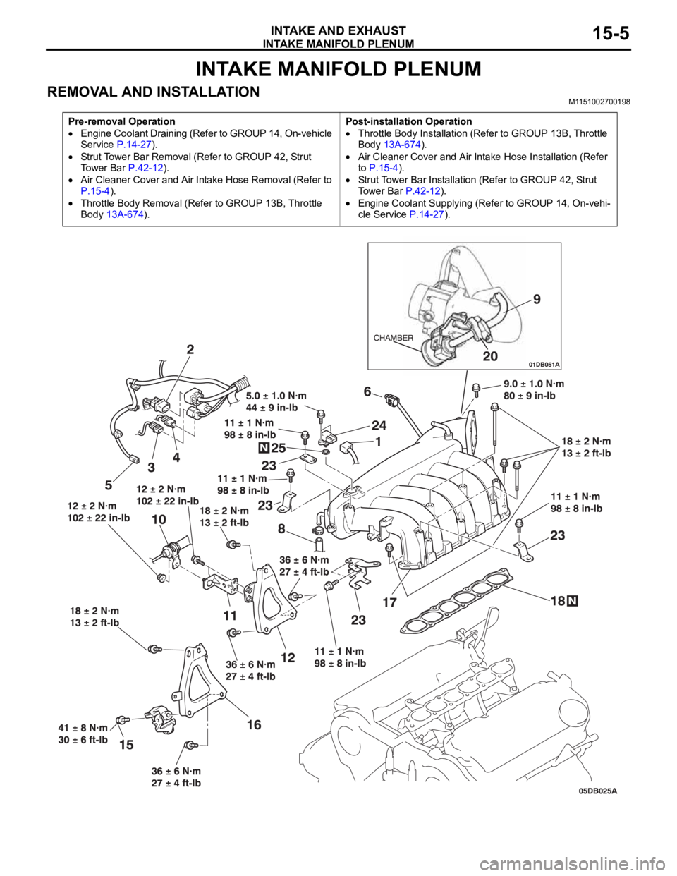
INTAKE MANIFOLD PLENUM
INTAKE AND EXHAUST15-5
INTAKE MANIFOLD PLENUM
REMOVAL AND INSTALLATION M1151002700198
Pre-removal Operation
Engine Coolant Draining (Refer to GROUP 14, On-vehicle
Service P.14-27).
Strut Tower Bar Removal (Refer to GROUP 42, Strut
To w e r B a r P.42-12).
Air Cleaner Cover and Air Intake Hose Removal (Refer to
P.15-4).
Throttle Body Removal (Refer to GROUP 13B, Throttle
Body 13A-674).Post-installation Operation
Throttle Body Installation (Refer to GROUP 13B, Throttle
Body 13A-674).
Air Cleaner Cover and Air Intake Hose Installation (Refer
to P.15-4).
Strut Tower Bar Installation (Refer to GROUP 42, Strut
Tower Bar P.42-12).
Engine Coolant Supplying (Refer to GROUP 14, On-vehi-
cle Service P.14-27).
Page 966 of 1500
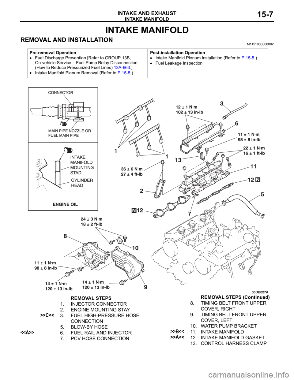
INTAKE MANIFOLD
INTAKE AND EXHAUST15-7
INTAKE MANIFOLD
REMOVAL AND INSTALLATION M1151003000802
Pre-removal Operation
Fuel Discharge Prevention [Refer to GROUP 13B,
On-vehicle Service
Fuel Pump Relay Disconnection
(How to Reduce Pressurized Fuel Lines) 13A-663.]
Intake Manifold Plenum Removal (Refer to P.15-5.)Post-installation Operation
Intake Manifold Plenum Installation (Refer to P.15-5.)
Fuel Leakage Inspection
REMOVAL STEPS
1. INJECTOR CONNECTOR
2. ENGINE MOUNTING STAY
>>C<<3. FUEL HIGH-PRESSURE HOSE
CONNECTION
5. BLOW-BY HOSE
<>6. FUEL RAIL AND INJECTOR
7. PCV HOSE CONNECTION8. TIMING BELT FRONT UPPER
COVER, RIGHT
9. TIMING BELT FRONT UPPER
COVER, LEFT
10. WATER PUMP BRACKET>>B<<11. INTAKE MANIFOLD
>>A<<12. INTAKE MANIFOLD GASKET
13. CONTROL HARNESS CLAMPREMOVAL STEPS (Continued)
Page 1008 of 1500
IGNITION SYSTEM
ENGINE ELECTRICAL16-31
ON-VEHICLE SERVICE
KNOCK CONTROL SYSTEM CHECKM1163001800081
Check the knock sensor circuit if diagnostic trouble code, No.
P0325 is shown.
Refer to GROUP 13B, Multiport Fuel Injection (MPI)
Multiport
Fuel Injection (MPI) Diagnosis
Diagnostic Trouble Code Pro-
cedures
DTC P0325 : Knock Sensor Circuit 13A-346.
IGNITION COIL CHECK M1163001200380
Check by the following procedure, and replace the coil if there
is a malfunction.
.
PRIMARY COIL AND IGNITION POWER
TRANSISTOR CONTINUITY CHECK
NOTE: No test can be performed on the Primary side of coil.
.
SECONDARY COIL CHECK
NOTE: It is impossible to check the secondary coil through the
continuity check as a diode is integrated in the secondary coil
circuit of this ignition coil. Accordingly, check the secondary coil
in the following procedure.
1. Disconnect the ignition coil connector.
2. Remove the ignition coil and install a new spark plug to the
ignition coil.
3. Connect the ignition coil connector.
4. Disable vehicle fuel pump by removing fuel pump relay or
disconnecting fuel pump connector D-18 (under rear seat).
5. Ground the side electrode of the spark plug and crank the
engine.
6. Check that spark is produced between the electrodes of the
spark plug.
7. If no spark is produced, replace the ignition coil with a new
one and recheck.
8. If spark is produced with the new ignition coil, replace the
old one as it is faulty. If no spark is produced again, the
ignition circuit is suspected as faulty. Check the ignition
circuit.
Page 1009 of 1500
IGNITION SYSTEM
ENGINE ELECTRICAL16-32
SPARK PLUG TESTM1163001500143
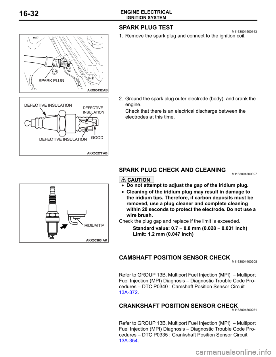
1. Remove the spark plug and connect to the ignition coil.
2. Ground the spark plug outer electrode (body), and crank the
engine.
Check that there is an electrical discharge between the
electrodes at this time.
SPARK PLUG CHECK AND CLEANING M1163004300397
Do not attempt to adjust the gap of the iridium plug.
Cleaning of the iridium plug may result in damage to
the iridium tips. Therefore, if carbon deposits must be
removed, use a plug cleaner and complete cleaning
within 20 seconds to protect the electrode. Do not use a
wire brush.
Check the plug gap and replace if the limit is exceeded.
Standard value: 0.7
0.8 mm (0.028 0.031 inch)
Limit: 1.2 mm (0.047 inch)
CAMSHAFT POSITION SENSOR CHECKM1163004400208
Refer to GROUP 13B, Multiport Fuel Injection (MPI) Multiport
Fuel Injection (MPI) Diagnosis
Diagnostic Trouble Code Pro-
cedures
DTC P0340 : Camshaft Position Sensor Circuit
13A-372.
CRANKSHAFT POSITION SENSOR CHECKM1163004500261
Refer to GROUP 13B, Multiport Fuel Injection (MPI) Multiport
Fuel Injection (MPI) Diagnosis
Diagnostic Trouble Code Pro-
cedures
DTC P0335 : Crankshaft Position Sensor Circuit
13A-354.
Page 1022 of 1500
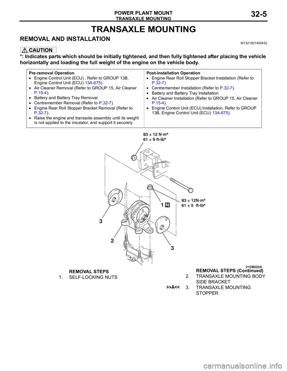
TRANSAXLE MOUNTING
POWER PLANT MOUNT32-5
TRANSAXLE MOUNTING
REMOVAL AND INSTALLATIONM1321001400452
*: Indicates parts which should be initially tightened, and then fully tightened after placing the vehicle
horizontally and loading the full weight of the engine on the vehicle body.
Pre-removal Operation
Engine Control Unit (ECU) , Refer to GROUP 13B,
Engine Control Unit (ECU) 13A-675).
Air Cleaner Removal (Refer to GROUP 15, Air Cleaner
P.15-4).
Battery and Battery Tray Removal
Centremember Removal (Refer to P.32-7).
Engine Rear Roll Stopper Bracket Removal (Refer to
P.32-7).
Raise the engine and transaxle assembly until its weight
is not applied to the insulator, and support it securely.Post-installation Operation
Engine Rear Roll Stopper Bracket Installation (Refer to
P.32-7).
Centremember Installation (Refer to P.32-7).
Battery and Battery Tray Installation
Air Cleaner Installation (Refer to GROUP 15, Air Cleaner
P.15-4).
Engine Control Unit (ECU) Installation, Refer to GROUP
13B, Engine Control Unit (ECU) 13A-675).
REMOVAL STEPS
1. SELF-LOCKING NUTS2. TRANSAXLE MOUNTING BODY
SIDE BRACKET
>>A<<3. TRANSAXLE MOUNTING
STOPPER REMOVAL STEPS (Continued)
Page 1330 of 1500
13-1
GROUP 13
FUEL
CONTENTS
MULTIPORT FUEL INJECTION (MFI) . . . . . . . . . . . . . . . . . . . .13A
FUEL SUPPLY . . . . . . . . . . . . . . . . . . . . . . . . . . . . . . . . . . . . . .13B
TRACTION CONTROL SYSTEM (TCL) . . . . . . . . . . . . . . . . . . .13C
Page 1494 of 1500
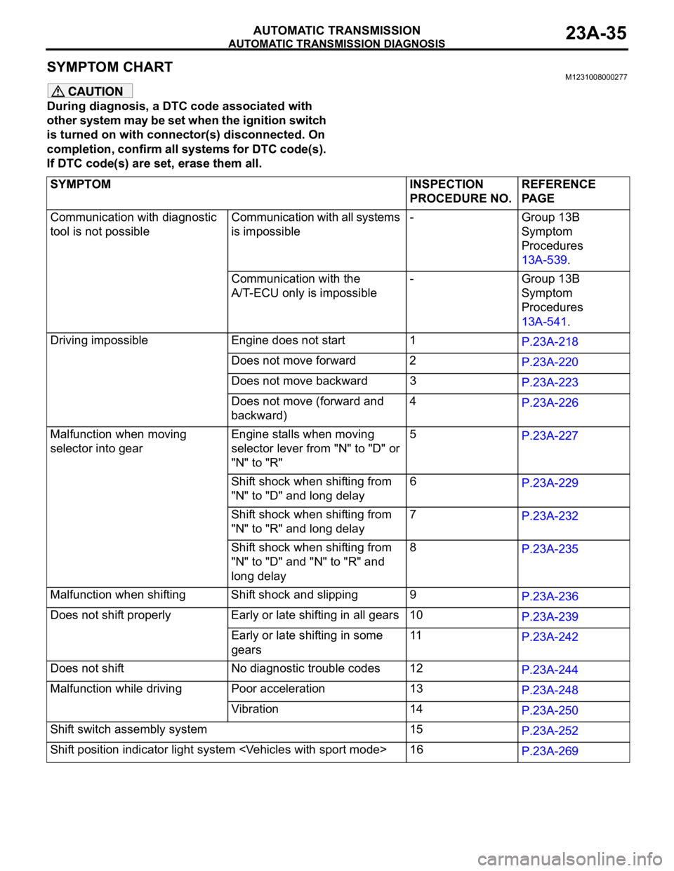
AUTOMATIC TRANSMISSION DIAGNOSIS
AUTOMATIC TRANSMISSION23A-35
SYMPTOM CHART M1231008000277
During diagnosis, a DTC code associated with
other system may be set when the ignition switch
is turned on with connector(s) disconnected. On
completion, confirm all systems for DTC code(s).
If DTC code(s) are set, erase them all.
SYMPTOM INSPECTION
PROCEDURE NO.REFERENCE
PA G E
Communication with diagnostic
tool is not possibleCommunication with all systems
is impossible- Group 13B
Symptom
Procedures
13A-539.
Communication with the
A/T-ECU only is impossible- Group 13B
Symptom
Procedures
13A-541.
Driving impossible Engine does not start 1
P.23A-218
Does not move forward 2
P.23A-220
Does not move backward 3
P.23A-223
Does not move (forward and
backward)4
P.23A-226
Malfunction when moving
selector into gearEngine stalls when moving
selector lever from "N" to "D" or
"N" to "R"5
P.23A-227
Shift shock when shifting from
"N" to "D" and long delay6
P.23A-229
Shift shock when shifting from
"N" to "R" and long delay 7
P.23A-232
Shift shock when shifting from
"N" to "D" and "N" to "R" and
long delay 8
P.23A-235
Malfunction when shifting Shift shock and slipping 9
P.23A-236
Does not shift properly Early or late shifting in all gears 10
P.23A-239
Early or late shifting in some
gears11
P.23A-242
Does not shift No diagnostic trouble codes 12
P.23A-244
Malfunction while driving Poor acceleration 13
P.23A-248
Vibration 14
P.23A-250
Shift switch assembly system 15
P.23A-252
Shift position indicator light system
P.23A-269