hood release MITSUBISHI 380 2005 Workshop Manual
[x] Cancel search | Manufacturer: MITSUBISHI, Model Year: 2005, Model line: 380, Model: MITSUBISHI 380 2005Pages: 1500, PDF Size: 47.87 MB
Page 494 of 1500
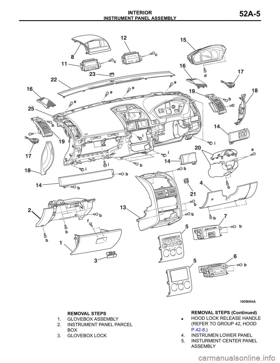
INSTRUMENT PANEL ASSEMBLY
INTERIOR52A-5
REMOVAL STEPS
1. GLOVEBOX ASSEMBLY
2. INSTRUMENT PANEL PARCEL
BOX
3. GLOVEBOX LOCKHOOD LOCK RELEASE HANDLE
(REFER TO GROUP 42, HOOD
P.42-8.)
4. INSTRUMEN LOWER PANEL
5. INSTURMENT CENTER PANEL
ASSEMBLY REMOVAL STEPS (Continued)
Page 1040 of 1500
GARNISHES AND MOLDINGS
EXTERIOR51-7
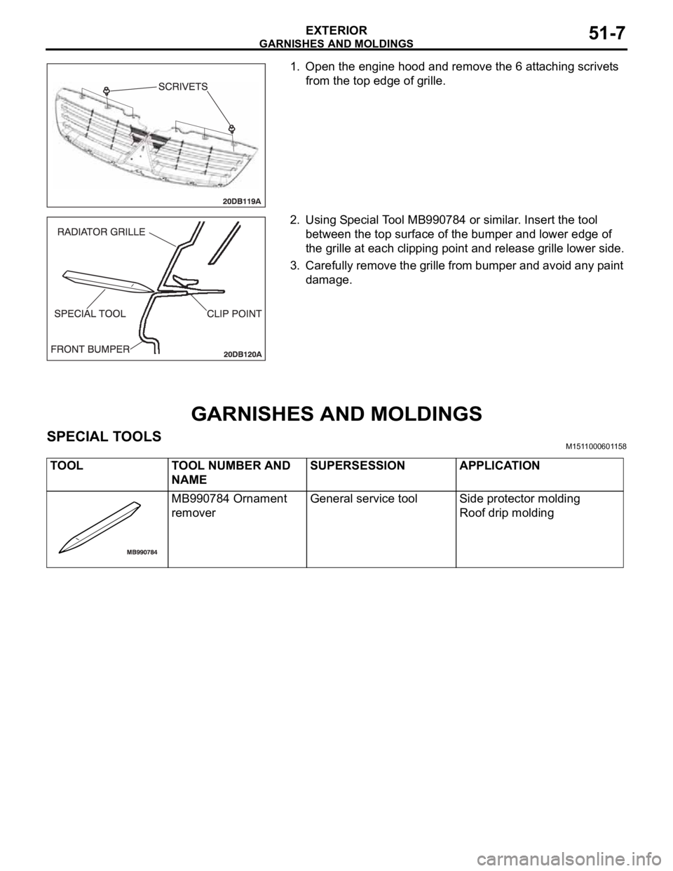
1. Open the engine hood and remove the 6 attaching scrivets
from the top edge of grille.
2. Using Special Tool MB990784 or similar. Insert the tool
between the top surface of the bumper and lower edge of
the grille at each clipping point and release grille lower side.
3. Carefully remove the grille from bumper and avoid any paint
damage.
GARNISHES AND MOLDINGS
SPECIAL TOOLSM1511000601158
TOOL TOOL NUMBER AND
NAMESUPERSESSION APPLICATION
MB990784 Ornament
removerGeneral service tool Side protector molding
Roof drip molding
Page 1071 of 1500
HOOD
BODY42-4
HOOD
BODY DIAGNOSIS
INTRODUCTION TO HOOD DIAGNOSISM1421005800363
Wind noise at the hood may be caused by improper
hood adjustment.
HOOD DIAGNOSTIC TROUBLESHOOTING STRATEGYM1421005900337
Use these steps to plan your diagnostic strategy. If
you follow them carefully, you will be sure that you
have exhausted most of the possible ways to find a
hood fault.
1. Gather information from the customer.2. Verify that the condition described by the
customer exists.
3. Find the malfunction by following the Symptom
Chart.
4. Verify malfunction is eliminated.
SYMPTOM CHARTM1421006000371
SYMPTOM PROCEDURES
INSPECTION PROCEDURE 1: Difficult Locking and Unlocking
DIAGNOSIS
STEP 1. Check that the release cable is routed
correctly.
Q: Is the release cable routed correctly?
YES :
Go to Step 2.
NO : Re-route the release cable. Then go to Step
4.
STEP 2. Check the engagement of the hood latch
and hood striker.
Q: Are the hood latch and hood striker engaged
correctly?
YES :
Go to Step 3.
NO : Adjust the hood latch (Refer to P.42-6).
Then go to Step 4.
STEP 3. Check for proper lubrication of release
cable.
Q: Is the release cable properly lubricated?
YES :
Go to Step 4.
NO : Lubricate, then go to Step 4.
STEP 4. Retest the system.
Q: Does the hood lock operate easily?
YES :
The procedure is complete.
NO : Return to Step 1. SYMPTOM INSPECTION
PROCEDUREREFERENCE PAGE
Difficult locking and unlocking 1
P.42-4
Uneven body clearance 2
P.42-5
Uneven height 3
P.42-5
Page 1073 of 1500
HOOD
BODY42-6
ON-VEHICLE SERVICE
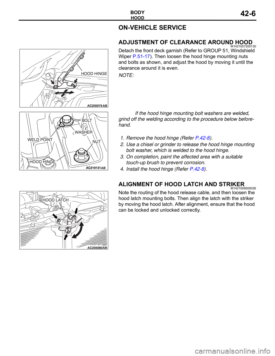
ADJUSTMENT OF CLEARANCE AROUND HOODM1421007200130
Detach the front deck garnish (Refer to GROUP 51, Windshield
Wiper P.51-17). Then loosen the hood hinge mounting nuts
and bolts as shown, and adjust the hood by moving it until the
clearance around it is even.
NOTE:
If the hood hinge mounting bolt washers are welded,
grind off the welding according to the procedure below before-
hand.
.
1. Remove the hood hinge (Refer P.42-8).
2. Use a chisel or grinder to release the hood hinge mounting
bolt washer, which is welded to the hood hinge.
3. On completion, paint the affected area with a suitable
touch-up brush to prevent corrosion.
4. Install the hood hinge (Refer P.42-8).
ALIGNMENT OF HOOD LATCH AND STRIKERM1421008500026
Note the routing of the hood release cable, and then loosen the
hood latch mounting bolts. Then align the latch with the striker
by moving the hood latch. After alignment, ensure that the hood
can be locked and unlocked correctly.
Page 1076 of 1500
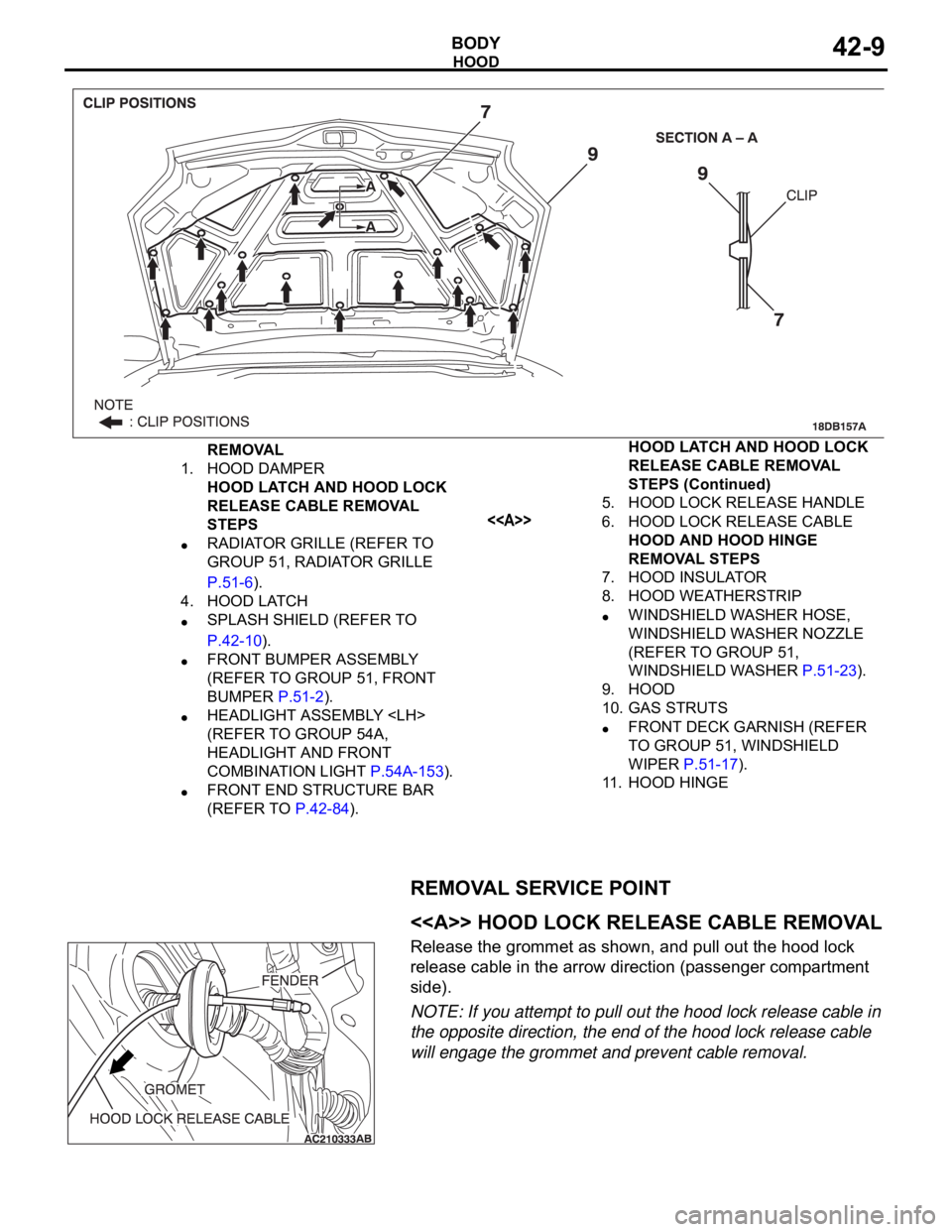
HOOD
BODY42-9
REMOVAL SERVICE POINT
.
<> HOOD LOCK RELEASE CABLE REMOVAL
Release the grommet as shown, and pull out the hood lock
release cable in the arrow direction (passenger compartment
side).
NOTE: If you attempt to pull out the hood lock release cable in
the opposite direction, the end of the hood lock release cable
will engage the grommet and prevent cable removal.
REMOVAL
1. HOOD DAMPER
HOOD LATCH AND HOOD LOCK
RELEASE CABLE REMOVAL
STEPS
RADIATOR GRILLE (REFER TO
GROUP 51, RADIATOR GRILLE
P.51-6).
4. HOOD LATCH
SPLASH SHIELD (REFER TO
P.42-10).
FRONT BUMPER ASSEMBLY
(REFER TO GROUP 51, FRONT
BUMPER P.51-2).
HEADLIGHT ASSEMBLY
(REFER TO GROUP 54A,
HEADLIGHT AND FRONT
COMBINATION LIGHT P.54A-153).
FRONT END STRUCTURE BAR
(REFER TO P.42-84).5. HOOD LOCK RELEASE HANDLE
<>6. HOOD LOCK RELEASE CABLE
HOOD AND HOOD HINGE
REMOVAL STEPS
7. HOOD INSULATOR
8. HOOD WEATHERSTRIP
WINDSHIELD WASHER HOSE,
WINDSHIELD WASHER NOZZLE
(REFER TO GROUP 51,
WINDSHIELD WASHER P.51-23).
9. HOOD
10. GAS STRUTS
FRONT DECK GARNISH (REFER
TO GROUP 51, WINDSHIELD
WIPER P.51-17).
11. HOOD HINGEHOOD LATCH AND HOOD LOCK
RELEASE CABLE REMOVAL
STEPS (Continued)
Page 1248 of 1500
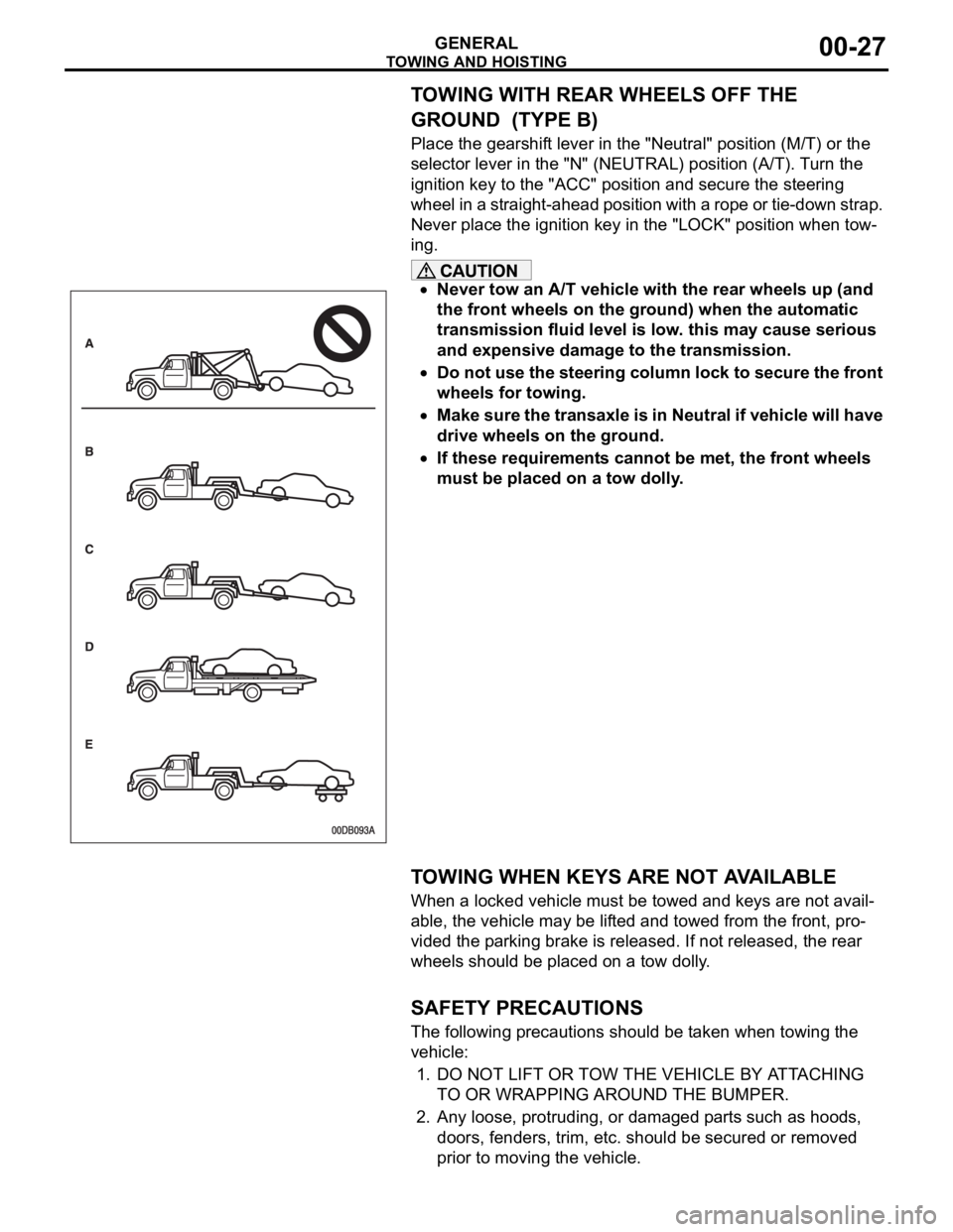
TOWING AND HOISTING
GENERAL00-27
TOWING WITH REAR WHEELS OFF THE
GROUND (TYPE B)
Place the gearshift lever in the "Neutral" position (M/T) or the
selector lever in the "N" (NEUTRAL) position (A/T). Turn the
ignition key to the "ACC" position and secure the steering
wheel in a straight-ahead position with a rope or tie-down strap.
Never place the ignition key in the "LOCK" position when tow-
ing.
Never tow an A/T vehicle with the rear wheels up (and
the front wheels on the ground) when the automatic
transmission fluid level is low. this may cause serious
and expensive damage to the transmission.
Do not use the steering column lock to secure the front
wheels for towing.
Make sure the transaxle is in Neutral if vehicle will have
drive wheels on the ground.
If these requirements cannot be met, the front wheels
must be placed on a tow dolly.
.
TOWING WHEN KEYS ARE NOT AVAILABLE
When a locked vehicle must be towed and keys are not avail-
able, the vehicle may be lifted and towed from the front, pro-
vided the parking brake is released. If not released, the rear
wheels should be placed on a tow dolly.
.
SAFETY PRECAUTIONS
The following precautions should be taken when towing the
vehicle:
1. DO NOT LIFT OR TOW THE VEHICLE BY ATTACHING
TO OR WRAPPING AROUND THE BUMPER.
2. Any loose, protruding, or damaged parts such as hoods,
doors, fenders, trim, etc. should be secured or removed
prior to moving the vehicle.
Page 1328 of 1500
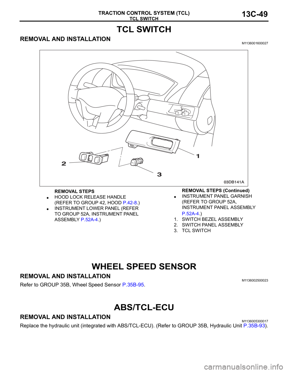
TCL SWITCH
TRACTION CONTROL SYSTEM (TCL)13C-49
TCL SWITCH
REMOVAL AND INSTALLATIONM1136001600027
WHEEL SPEED SENSOR
REMOVAL AND INSTALLATIONM1136002500023
Refer to GROUP 35B, Wheel Speed Sensor P.35B-95.
ABS/TCL-ECU
REMOVAL AND INSTALLATIONM1136005300017
Replace the hydraulic unit (integrated with ABS/TCL-ECU). (Refer to GROUP 35B, Hydraulic Unit P.35B-93).
REMOVAL STEPS
HOOD LOCK RELEASE HANDLE
(REFER TO GROUP 42, HOOD P.42-8.)
INSTRUMENT LOWER PANEL (REFER
TO GROUP 52A, INSTRUMENT PANEL
ASSEMBLY P.52A-4.)
INSTRUMENT PANEL GARNISH
(REFER TO GROUP 52A,
INSTRUMENT PANEL ASSEMBLY
P.52A-4.)
1. SWITCH BEZEL ASSEMBLY
2. SWITCH PANEL ASSEMBLY
3. TCL SWITCH REMOVAL STEPS (Continued)