Shift MITSUBISHI 380 2005 Workshop Manual
[x] Cancel search | Manufacturer: MITSUBISHI, Model Year: 2005, Model line: 380, Model: MITSUBISHI 380 2005Pages: 1500, PDF Size: 47.87 MB
Page 499 of 1500
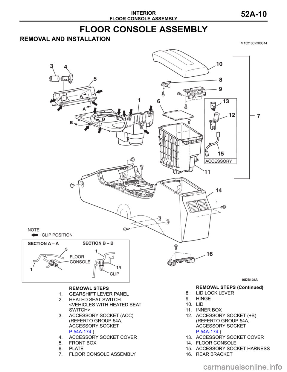
FLOOR CONSOLE ASSEMBLY
INTERIOR52A-10
FLOOR CONSOLE ASSEMBLY
REMOVAL AND INSTALLATIONM1521002200314
REMOVAL STEPS
1. GEARSHIFT LEVER PANEL
2. HEATED SEAT SWITCH
3. ACCESSORY SOCKET (ACC)
(REFERTO GROUP 54A,
ACCESSORY SOCKET
P.54A-174.)
4. ACCESSORY SOCKET COVER
5. FRONT BOX
6. PLATE
7. FLOOR CONSOLE ASSEMBLY8. LID LOCK LEVER
9. HINGE
10. LID
11. INNER BOX
12. ACCESSORY SOCKET (+B)
(REFERTO GROUP 54A,
ACCESSORY SOCKET
P.54A-174.)
13. ACCESSORY SOCKET COVER
14. FLOOR CONSOLE
15. ACCESSORY SOCKET HARNESS
16. REAR BRACKETREMOVAL STEPS (Continued)
Page 566 of 1500
FLOOR, SEAT AND ROOF
CONFIGURATION DIAGRAMS80-17
FLOOR, SEAT AND ROOFM1801000900930
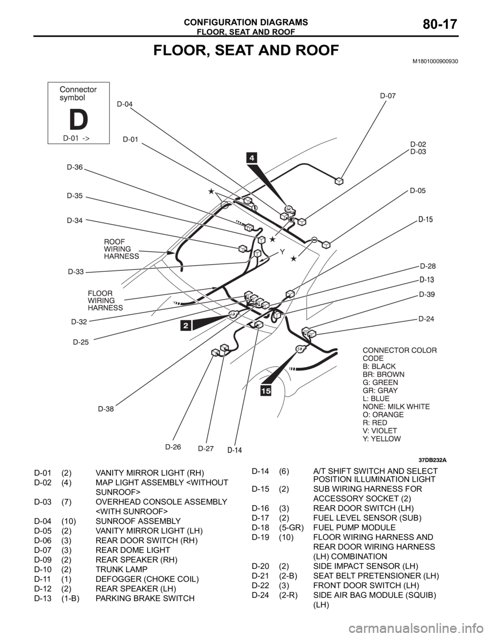
D-01 (2) VANITY MIRROR LIGHT (RH)
D-02 (4) MAP LIGHT ASSEMBLY
D-03 (7) OVERHEAD CONSOLE ASSEMBLY
D-04 (10) SUNROOF ASSEMBLY
D-05 (2) VANITY MIRROR LIGHT (LH)
D-06 (3) REAR DOOR SWITCH (RH)
D-07 (3) REAR DOME LIGHT
D-09 (2) REAR SPEAKER (RH)
D-10 (2) TRUNK LAMP
D-11 (1) DEFOGGER (CHOKE COIL)
D-12 (2) REAR SPEAKER (LH)
D-13 (1-B) PARKING BRAKE SWITCHD-14 (6) A/T SHIFT SWITCH AND SELECT
POSITION ILLUMINATION LIGHT
D-15 (2) SUB WIRING HARNESS FOR
ACCESSORY SOCKET (2)
D-16 (3) REAR DOOR SWITCH (LH)
D-17 (2) FUEL LEVEL SENSOR (SUB)
D-18 (5-GR) FUEL PUMP MODULE
D-19 (10) FLOOR WIRING HARNESS AND
REAR DOOR WIRING HARNESS
(LH) COMBINATION
D-20 (2) SIDE IMPACT SENSOR (LH)
D-21 (2-B) SEAT BELT PRETENSIONER (LH)
D-22 (3) FRONT DOOR SWITCH (LH)
D-24 (2-R) SIDE AIR BAG MODULE (SQUIB)
(LH)
Page 1189 of 1500
BRAKE PEDAL
BASIC BRAKE SYSTEM35A-24
BRAKE PEDAL
REMOVAL AND INSTALLATIONM1351003400406
Post-installation Operation
Brake Pedal Adjustment (Refer to P.35A-13).
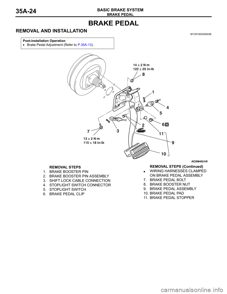
REMOVAL STEPS
1. BRAKE BOOSTER PIN
2. BRAKE BOOSTER PIN ASSEMBLY
3. SHIFT LOCK CABLE CONNECTION
4. STOPLIGHT SWITCH CONNECTOR
5. STOPLIGHT SWITCH
6. BRAKE PEDAL CLIPWIRING HARNESSES CLAMPED
ON BRAKE PEDAL ASSEMBLY
7. BRAKE PEDAL BOLT
8. BRAKE BOOSTER NUT
9. BRAKE PEDAL ASSEMBLY
10. BRAKE PEDAL PAD
11. BRAKE PEDAL STOPPERREMOVAL STEPS (Continued)
Page 1247 of 1500
TOWING AND HOISTING
GENERAL00-26
TOWING AND HOISTINGM1001000800380
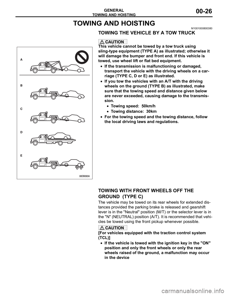
TOWING THE VEHICLE BY A TOW TRUCK
.
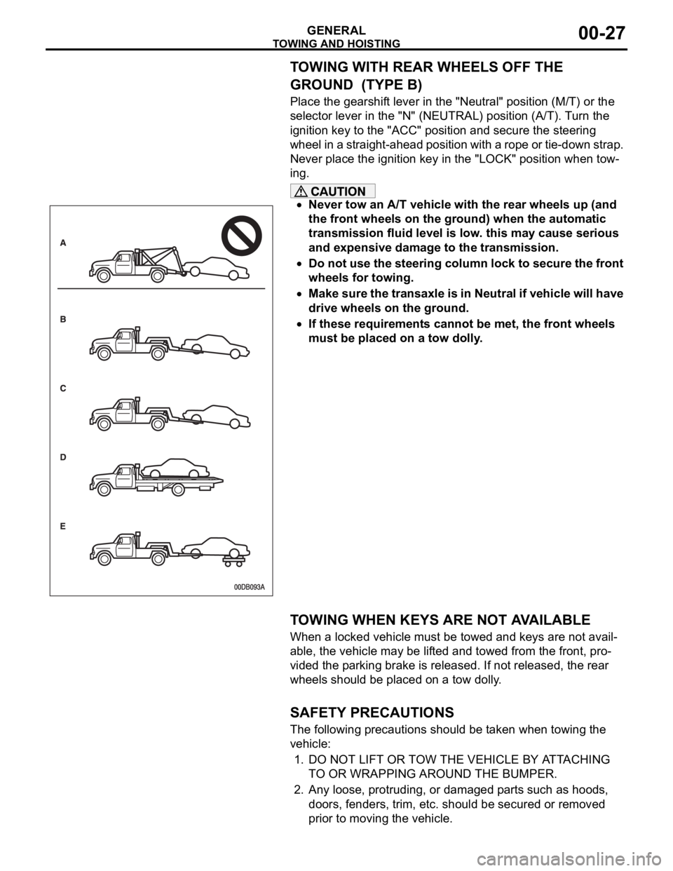
This vehicle cannot be towed by a tow truck using
sling-type equipment (TYPE A) as illustrated; otherwise it
will damage the bumper and front end. If this vehicle is
towed, use wheel lift or flat bed equipment.
If the transmission is malfunctioning or damaged,
transport the vehicle with the driving wheels on a car-
riage (TYPE C, D or E) as illustrated.
If you tow the vehicles with an A/T with the driving
wheels on the ground (TYPE B) as illustrated, make
sure that the towing speed and distance given below
are never exceeded, causing damage to the transmis-
sion.
Towing speed: 50km/h
Towing distance: 30km
For the towing speed and the towing distance, follow
the local driving laws and regulations.
.
TOWING WITH FRONT WHEELS OFF THE
GROUND (TYPE C)
The vehicle may be towed on its rear wheels for extended dis-
tances provided the parking brake is released and gearshift
lever is in the "Neutral" position (M/T) or the selector lever is in
the "N" (NEUTRAL) position (A/T). It is recommended that vehi-
cles be towed using the front pickup whenever possible.
[For vehicles equipped with the traction control system
(TCL)]
If the vehicle is towed with the ignition key in the "ON"
position and only the front wheels or only the rear
wheels raised of the ground, a malfunction may occur
in the device
.
Page 1248 of 1500
TOWING AND HOISTING
GENERAL00-27
TOWING WITH REAR WHEELS OFF THE
GROUND (TYPE B)
Place the gearshift lever in the "Neutral" position (M/T) or the
selector lever in the "N" (NEUTRAL) position (A/T). Turn the
ignition key to the "ACC" position and secure the steering
wheel in a straight-ahead position with a rope or tie-down strap.
Never place the ignition key in the "LOCK" position when tow-
ing.
Never tow an A/T vehicle with the rear wheels up (and
the front wheels on the ground) when the automatic
transmission fluid level is low. this may cause serious
and expensive damage to the transmission.
Do not use the steering column lock to secure the front
wheels for towing.
Make sure the transaxle is in Neutral if vehicle will have
drive wheels on the ground.
If these requirements cannot be met, the front wheels
must be placed on a tow dolly.
.
TOWING WHEN KEYS ARE NOT AVAILABLE
When a locked vehicle must be towed and keys are not avail-
able, the vehicle may be lifted and towed from the front, pro-
vided the parking brake is released. If not released, the rear
wheels should be placed on a tow dolly.
.
SAFETY PRECAUTIONS
The following precautions should be taken when towing the
vehicle:
1. DO NOT LIFT OR TOW THE VEHICLE BY ATTACHING
TO OR WRAPPING AROUND THE BUMPER.
2. Any loose, protruding, or damaged parts such as hoods,
doors, fenders, trim, etc. should be secured or removed
prior to moving the vehicle.
Page 1267 of 1500
![MITSUBISHI 380 2005 Workshop Manual MAINTENANCE SERVICE
GENERAL00-46
NOTE: If it takes some amount of time until the transmission
fluid reaches its normal operating temperature [70
80C
(158
176F)], check the transmission fluid lev MITSUBISHI 380 2005 Workshop Manual MAINTENANCE SERVICE
GENERAL00-46
NOTE: If it takes some amount of time until the transmission
fluid reaches its normal operating temperature [70
80C
(158
176F)], check the transmission fluid lev](/img/19/57086/w960_57086-1266.png)
MAINTENANCE SERVICE
GENERAL00-46
NOTE: If it takes some amount of time until the transmission
fluid reaches its normal operating temperature [70
80C
(158
176F)], check the transmission fluid level by refer-
ring to the left diagram.
2. Park the vehicle on a level surface.
3. Move the selector lever through all positions to fill the torque
converter and the hydraulic circuits with fluid, and then move
the selector lever to the "N" position.
4. After wiping off any dirt around the dipstick, remove the
dipstick and check the condition of the transmission fluid.
NOTE: If the transmission fluid smells as if it is burnt, it
means that the transmission fluid has been contaminated by
fine particles from the bushings and friction materials. Tran-
saxle overhaul and cooler line flushing may be necessary.
5. Check transmission fluid level is at the "HOT" mark on the
dipstick. If the transmission fluid level is less than this, add
DIAMOND ATF SP III until the level reaches the "HOT"
mark.
NOTE: If the transmission fluid level is too low, the oil pump
will draw in air along with the transmission fluid, which will
cause to form bubbles. If the transmission fluid level is too
high, rotating components inside the transaxle will churn the
fluid and air into a foamy liquid. Both conditions (level too
low or too high) will cause the hydraulic pressure to drop,
which will result in late shifting and slipping of the clutches
and brakes.
NOTE: In either case, air bubbles can interfere with normal
valve, clutch, and brake operation. Also, foaming can cause
transmission fluid to escape from the transaxle vent where it
may be mistaken for a leak.
Page 1346 of 1500

AUTO-CRUISE CONTROL
ENGINE AND EMISSION CONTROL17-15
DIAGNOSTIC TROUBLE CODE PROCEDURES
DTC P0830: Clutch Switch (5M/T Only)
.
CIRCUIT OPERATION
A 5 Volt power supply is applied to the clutch
switch output terminal (terminal No. 1) from the
ENGINE-ECU(terminal No. B-21 pin 41) when
the clutch pedal is applied the power supply is
switched to earth.
.
TECHNICAL DESCRIPTION
The ENGINE-ECU uses the clutch switch earth-
ing as a signal that clutch pedal has been
applied.
.
DTC SET CONDITIONS
Check Conditions
Vehicle speed is above 50 km/h.Judgement Criteria
Gear shift is above 5 times.
Clutch control is below 2 times.
No MIL.
No Limp home.
.
TROUBLESHOOTING HINTS (The most
likely causes for this code to be set are:)
Clutch switch failed
Harness damage in clutch switch circuit, or con-
nector damage.
Refer to component locations GROUP-70
Refer to configuration diagrams GROUP-80
Refer to circuit diagrams GROUP-90
DIAGNOSIS
Required Special Tools:
: Diagnostic tool (MUT-III Sub Assembly)
MB991824: V.C.I.
MB991827: USB Cable
MB991910: Main Harness A
Page 1396 of 1500

AUTO-CRUISE CONTROL
ENGINE AND EMISSION CONTROL17-65
DATA LIST REFERENCE TABLE - Auto Cruise ControlM1172002400471
When shifting the selector lever to "D" range, apply the brakes so that the vehicle does not move
forward.
Driving tests always need two persons: one driver and one observer.
NOTE: *:After the inspection is completed, disconnect the throttle position sensor connector, and then delete
the diagnostic trouble code using use of Diagnostic Tool MB991958. (Refer to P.17-11).
MUT-III
Diagnostic
To o l
DISPLAYITEM
NO.INSPECTION ITEM INSPECTION REQUIREMENT NORMAL
CONDITION
APS
SNS(MAIN)11 A c c e l e r a t o r p e d a l
position sensor (main)Ignition
switch:
"ON"Accelerator pedal: Released
435
1,035 mV
Accelerator pedal: Gradually
depressedIncreases in
response to the
pedal depression
stroke
Accelerator pedal: Fully
depressed4,000 mV or more
BRAKE SW 89 Stoplamp switch Brake pedal: Depressed ON
Brake pedal: Released OFF
CANCEL
CODE57 Cancel code Ignition switch: "ON" The cancel code,
which set when the
auto-cruise control
system was
cancelled at the
last time, is set
again.
CANCEL
SWITCH75 Auto-cruise
control
switchCANCEL "CANCEL" switch: ON ON
"CANCEL" switch: OFF OFF
CLUTCH SW 78 Transmission inhibitor
switchTransmission inhibitor switch: "P" or
"N"ON
Transmission inhibitor switch: Other
than aboveOFF
CRUISE 81 Auto-cruise control
system operationAuto-cruise control system: active ON
Auto-cruise control system: Inactive OFF
MAIN SW 86 Auto-cruise
control
switchCRUISE
(MAIN)"CRUISE" (MAIN) switch: "ON" ON
"CRUISE" (MAIN) switch: "OFF" OFF
RESUME
SWITCH91 Auto-cruise
control
switchACC/RES "ACC/RES" switch: ON ON
"ACC/RES" switch: OFF OFF
SET SWITCH 92 Auto-cruise
control
switchCOAST/S
ET"COAST/SET" switch: ON ON
"COAST/SET" switch: OFF OFF
STOPLIGHT
SW74 Stoplamp switch Brake pedal: Depressed ON
Brake pedal: Released OFF
Page 1462 of 1500

GENERAL DESCRIPTION
AUTOMATIC TRANSMISSION23A-3
GENERAL DESCRIPTIONM1231000100366
ITEM SPECIFICATION
Transmission modelF5A5A-4-C5Z
Engine model 6G75-S4-MP
Torque converter Type 3-element, 1-stage, 2-phase type
Lock-up Provided
Stall torque ratio 1.71
Transmission type5 forward speeds, 1 reverse speed, fully automatic
Transmission gear
ratio1st 3.789
2nd 2.162
3rd 1.421
4th 1.000
5th 0.686
Reverse 3.117
Final reduction ratio (Differential gear ratio) 3.325
Clutch Multi-disc type 4 sets
Brake Multi-disc type 2 sets, band type 1 set
Manual control system P-R-N-D (4 position) + Sport mode (up, down)
Shift pattern control Electronic control
Hydraulic control during shifting Electronic control (Each clutch hydraulically independently
controlled)
Torque converter clutch control Electronic control
Transmission fluid Specified lubricants MITSUBISHI ELC4-SP III
Quantity (litres) 8.4
Page 1466 of 1500
GENERAL DESCRIPTION
AUTOMATIC TRANSMISSION23A-7
ELECTRONICALLY-CONTROLLED SYSTEM
.
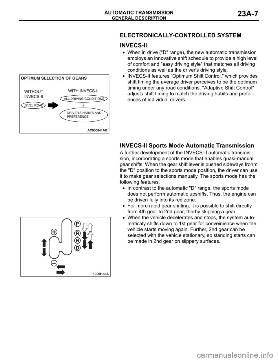
INVECS-II
When in drive ("D" range), the new automatic transmission
employs an innovative shift schedule to provide a high level
of comfort and "easy driving style" that matches all driving
conditions as well as the driver's driving style.
INVECS-II features "Optimum Shift Control," which provides
shift timing the average driver perceives to be the optimum
timing under any road conditions. "Adaptive Shift Control"
adjusts shift timing to match the driving habits and prefer-
ences of individual drivers.
.
INVECS-II Sports Mode Automatic Transmission
A further development of the INVECS-II automatic transmis-
sion, incorporating a sports mode that enables quasi-manual
gear shifts. When the gear shift lever is pushed sideways fronm
the "D" position to the sports mode position, the driver can use
it to make gear selections manually. The sports mode has the
following features.
In contrast to the automatic "D" range, the sports mode
does not perform automatic upshifts. Thus, the engine can
be driven fully into its red zone.
For more rapid gear shifting, it is possible to shift directly
from 4th gear to 2nd gear, therby skipping a gear.
When the vehicle decelerates and stops, the system auto-
maticaly shifts down to 1st gear for conveinience when the
vehicle starts moving again. Further, 2nd gear can be
selected with the vehicle stationary, so standing starts can
be made in 2nd gear on slippery surfaces.
.