Speed warning light MITSUBISHI 380 2005 Workshop Manual
[x] Cancel search | Manufacturer: MITSUBISHI, Model Year: 2005, Model line: 380, Model: MITSUBISHI 380 2005Pages: 1500, PDF Size: 47.87 MB
Page 5 of 1500

GENERAL DESCRIPTION
SIMPLIFIED WIRING SYSTEM (SWS)54B-5
INTERMITTENT CONTROL
ETACS-ECU uses the dial position of the variable
intermittent wiper control switch and the vehicle
speed signal sent by the combination meter to calcu-
late the interval to be sent to the front-ECU. The
front-ECU determines the intermittent time from the
input SWS data signal, and turns ON the windshield
wiper drive signal. When the wiper is at the STOP
position, the windshield wiper auto-stop signal goes
OFF to turn OFF the windshield wiper drive signal.
After the intermittent time from when the windshield
wiper drive signal turned ON, the windshield wiper
drive signal is turned ON again and the above opera-
tion is repeated.
.
MIST WIPER CONTROL
When the ignition switch is in the ACC or ON posi-
tion, and the windshield mist wiper switch of the col-
umn switch is turned ON, the front-ECU turns ON the
windshield wiper drive signal. At the same time, the
wiper speed switching relay is turned ON
(HIGH-SPEED). While the windshield mist wiper
switch is ON, the windshield wiper will operate at
high speed. Then, if the windshield mist wiper switch
is turned off, the wiper operates at low speed until it
stops at the predetermined park position.
When the windshield mist switch is turned on briefly,
the wiper operates once at low speed.
At the point the windshield mist switch is turned ON,
if the windshield wiper has been operating intermit-
tently, the same operations as the above will be per-
formed while the windshield mist wiper switch is ON.
After the windshield mist wiper switch goes OFF, the
intermittent operations will be set again after the
windshield wiper auto-stop signal last is turned ON.
.
WASHER CONTROL
When the ignition switch is in the ACC or ON posi-
tion, and the windshield washer switch of the column
switch is turned ON, the front-ECU turns ON the
windshield washer relay. The windshield wiper drive
signal is turned ON in 0.15 seconds until 2 seconds
after the windshield washer switch goes OFF to
operate the windshield wiper continuously. When the
windshield washer switch is turned ON, if the wind-
shield wiper is operating intermittently, intermittent
operations will be continued after continuous opera-
tions.
HEADLAMP
.
HEADLAMP AUTOMATIC SHUTDOWN
FUNCTION
Even if the lighting switch (tail lamp switch or
headlamp switch) is ON, the headlamps and tail
lamps will automatically go off in the following condi-
tions to prevent the battery from discharging:
When the ignition key is turned from "ON" to "LOCK"
(OFF) or "ACC" position with the lighting switch
turned ON, and this state continues for three min-
utes, the lamp will automatically be turned off. If the
driver's seat door is opened during these three min-
utes, the lamp will go off one second later.
.
HIGH-BEAM INDICATOR
At the same time that the high beams are illumi-
nated, the ETACS-ECU sends a signal to illuminate
the high-beam indicator via the CAN bus line. The
combination meter receives the transmitted signal
and turns the high-beam indicator on and off.
FLASHER TIMER
.
TURN-SIGNAL LAMP
The turn-signal lamp output (flashing signal) is
turned ON when the ignition switch is ON and the
turn-signal lamp switch is ON (LH or RH). If the front
turn-signal lamp or rear turn-signal lamp bulb has
burned out, the flashing speed increases to indicate
that the bulb has burned out.
.
HAZARD WARNING LAMP
Detects the signal where the hazard warning lamp
switch input changes from OFF to ON, and reverse
the flashing state according to this signal. The haz-
ard warning lamps toggle on and off whenever the
hazard warning lamp switch is operated.
.
TURN-SIGNAL INDICATORS
At the same time that the turn-signal lamps are illu-
minated, the ETACS-ECU sends a signal to illumi-
nate the turn-signal lamp indicator via the CAN bus
line. The combination meter receives the transmitted
signal and turns the turn-signal lamp indicator on and
off.
Page 398 of 1500

SYMPTOM PROCEDURES
SIMPLIFIED WIRING SYSTEM (SWS)54B-398
INSPECTION PROCEDURE K-7: Interior Light: The seat belt warning lamp do not illuminate or go out
normally
NOTE: This troubleshooting procedure requires the
use of diagnostic tool MB991958 and SWS monitor
kit MB991813. For details on how to use the SWS
monitor, refer to "How to connect SWS monitor
P.54B-13."
.
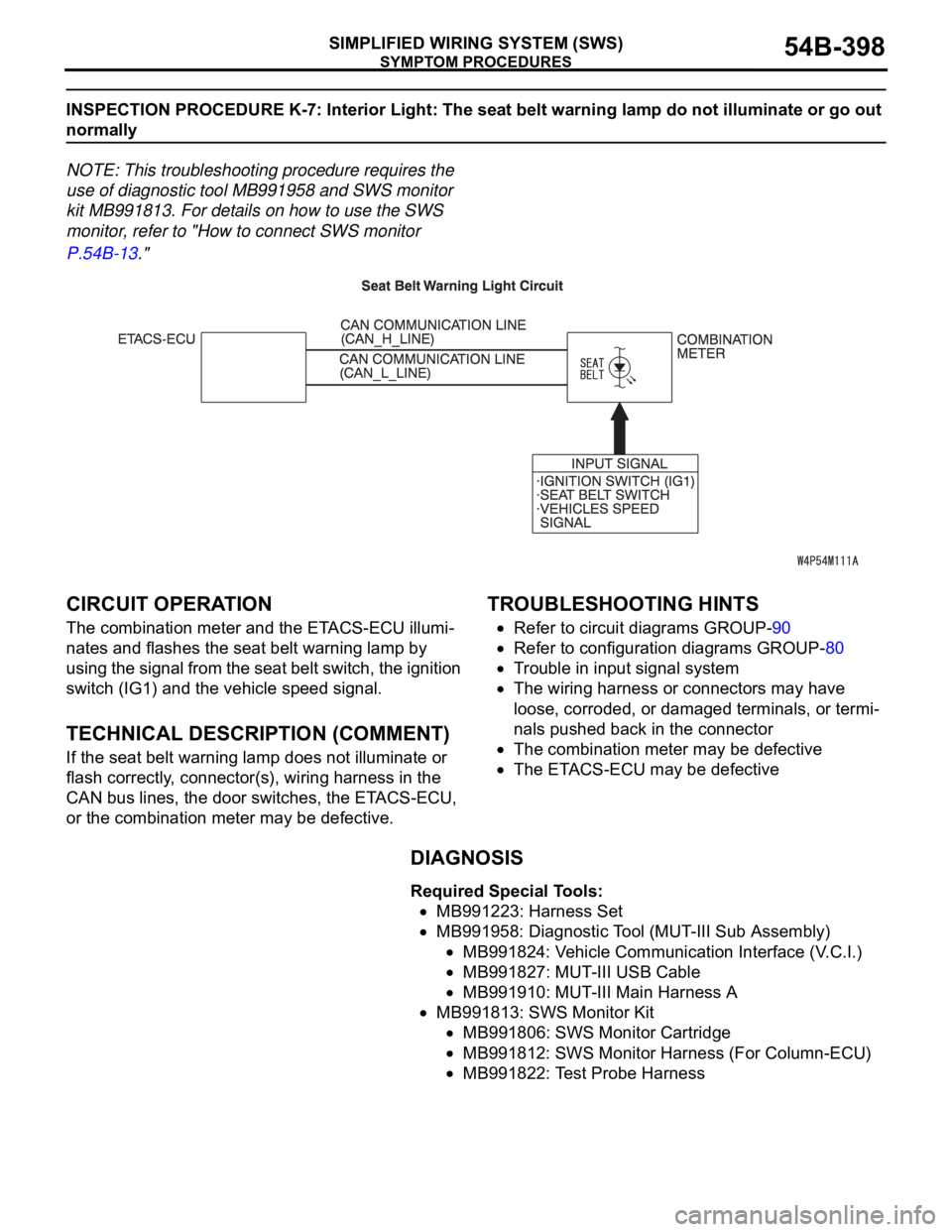
CIRCUIT OPERATION
The combination meter and the ETACS-ECU illumi-
nates and flashes the seat belt warning lamp by
using the signal from the seat belt switch, the ignition
switch (IG1) and the vehicle speed signal.
.
TECHNICAL DESCRIPTION (COMMENT)
If the seat belt warning lamp does not illuminate or
flash correctly, connector(s), wiring harness in the
CAN bus lines, the door switches, the ETACS-ECU,
or the combination meter may be defective.
.
TROUBLESHOOTING HINTS
Refer to circuit diagrams GROUP-90
Refer to configuration diagrams GROUP-80
Trouble in input signal system
The wiring harness or connectors may have
loose, corroded, or damaged terminals, or termi-
nals pushed back in the connector
The combination meter may be defective
The ETACS-ECU may be defective
DIAGNOSIS
Required Special Tools:
MB991223: Harness Set
MB991958: Diagnostic Tool (MUT-III Sub Assembly)
MB991824: Vehicle Communication Interface (V.C.I.)
MB991827: MUT-III USB Cable
MB991910: MUT-III Main Harness A
MB991813: SWS Monitor Kit
MB991806: SWS Monitor Cartridge
MB991812: SWS Monitor Harness (For Column-ECU)
MB991822: Test Probe Harness
Page 1472 of 1500

AUTOMATIC TRANSMISSION DIAGNOSIS
AUTOMATIC TRANSMISSION23A-13
A/T DIAGNOSTIC TROUBLESHOOTING STRATEGYM1231007600339
Use these steps to plan your diagnostic strategy. If
you follow them carefully, you will find most A/T mal-
functions.
1. Gather as much information as possible about the
complaint from the customer.
2. Verify that the condition described by the
customer exists.
3. Check the vehicle for any A/T Diagnostic Trouble
Codes (DTCs).
4. If you can not verify the condition and there are no
DTCs, the malfunction is intermittent. For
information on how to cope with intermittent
malfunctions, refer to GROUP 00, How to Use
Troubleshooting/Inspection Service Points
How
to Cope with Intermittent Malfunction P.00-14.
5. If you can verify the condition but there are no
DTCs, or the system can not communicate with
diagnostic tool, refer to the Symptom Chart
P.23A-35.6. If there is a DTC, record the number of the code,
then erase the code from memory using
diagnostic tool.
7. Reconfirm the symptom with a Road Test.
8. If a DTC is set again, go to the Inspection Chart
for Diagnostic Trouble Codes.
9. If a DTC is not set again, the malfunction is
intermittent. For information on how to cope with
intermittent malfunctions, refer to GROUP 00,
How to Use Troubleshooting/Inspection Service
Points
How to Cope with Intermittent
Malfunction P.00-14.
10.After repairs are completed, conduct a Road Test
duplicating the complaint conditions to confirm the
malfunction has been eliminated.
DIAGNOSTIC FUNCTIONM1231022500135
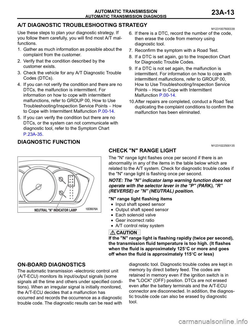
CHECK "N" RANGE LIGHT
The "N" range light flashes once per second if there is an
abnormality in any of the items in the table below which are
related to the A/T system. Check for diagnostic trouble codes if
the "N" range light is flashing once per second.
NOTE: The "N" indicator lamp warning function does not
operate with the selector lever in the "P" (PARK), "R"
(REVERSE) or "N" (NEUTRAL) position.
"N" range light flashing items
Input shaft speed sensor
Output shaft speed sensor
Each solenoid valve
Gear incorrect ratio
A/T control relay system
If the "N" range light is flashing rapidly (twice per second),
the transmission fluid temperature is too high. (It flashes
when the fluid is approximately 125
C or more and goes
off when the fluid is approximately 115
C or less)
ON-BOARD DIAGNOSTICS
The automatic transmission -electronic control unit
(A/T-ECU) monitors its input/output signals (some
signals all the time and others under specified condi-
tions). When an irregular signal is initially monitored,
the A/T-ECU decides that a malfunction has
occurred and records the occurrence as a diagnostic
trouble code. The diagnostic results can be read with diagnostic tool. Diagnostic trouble codes are kept in
memory by direct battery feed. The codes are
retained in memory even if the ignition switch is in
the "LOCK" (OFF) position. DTCs are not erased
even after the battery terminals and the A/T-ECU
connector are disconnected. In addition, the diagnos-
tic trouble code can also be erased by diagnostic
tool.