battery location MITSUBISHI 380 2005 Workshop Manual
[x] Cancel search | Manufacturer: MITSUBISHI, Model Year: 2005, Model line: 380, Model: MITSUBISHI 380 2005Pages: 1500, PDF Size: 47.87 MB
Page 822 of 1500

AUTO A/C DIAGNOSIS
HEATER, AIR CONDITIONING AND VENTILATION55-121
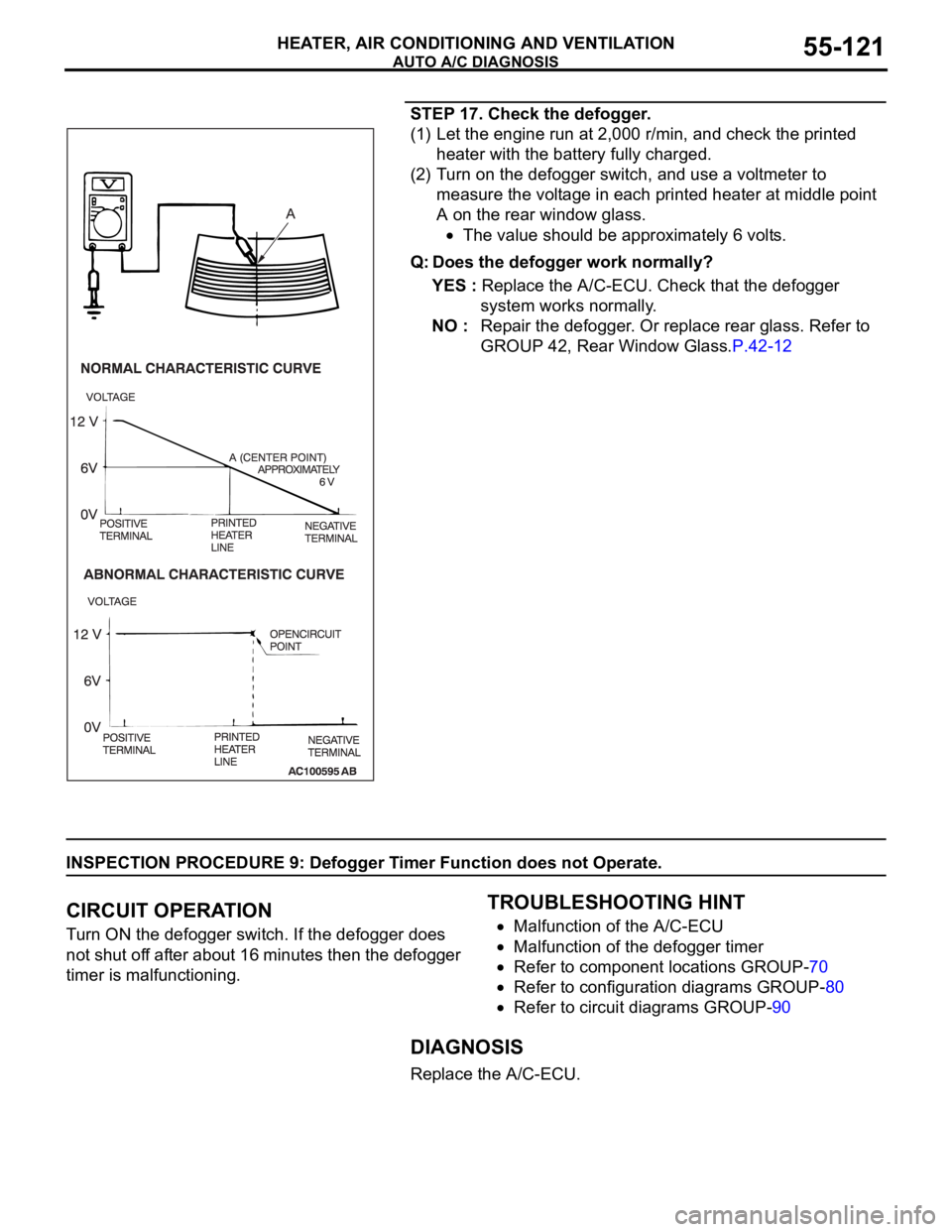
STEP 17. Check the defogger.
(1) Let the engine run at 2,000 r/min, and check the printed
heater with the battery fully charged.
(2) Turn on the defogger switch, and use a voltmeter to
measure the voltage in each printed heater at middle point
A on the rear window glass.
The value should be approximately 6 volts.
Q: Does the defogger work normally?
YES : Replace the A/C-ECU. Check that the defogger
system works normally.
NO : Repair the defogger. Or replace rear glass. Refer to
GROUP 42, Rear Window Glass.P.42-12
INSPECTION PROCEDURE 9: Defogger Timer Function does not Operate.
.
CIRCUIT OPERATION
Turn ON the defogger switch. If the defogger does
not shut off after about 16 minutes then the defogger
timer is malfunctioning.
.
TROUBLESHOOTING HINT
Malfunction of the A/C-ECU
Malfunction of the defogger timer
Refer to component locations GROUP-70
Refer to configuration diagrams GROUP-80
Refer to circuit diagrams GROUP-90
DIAGNOSIS
Replace the A/C-ECU.
Page 1243 of 1500

PRECAUTIONS BEFORE SERVICE
GENERAL00-22
ENGINE MODEL STAMPING
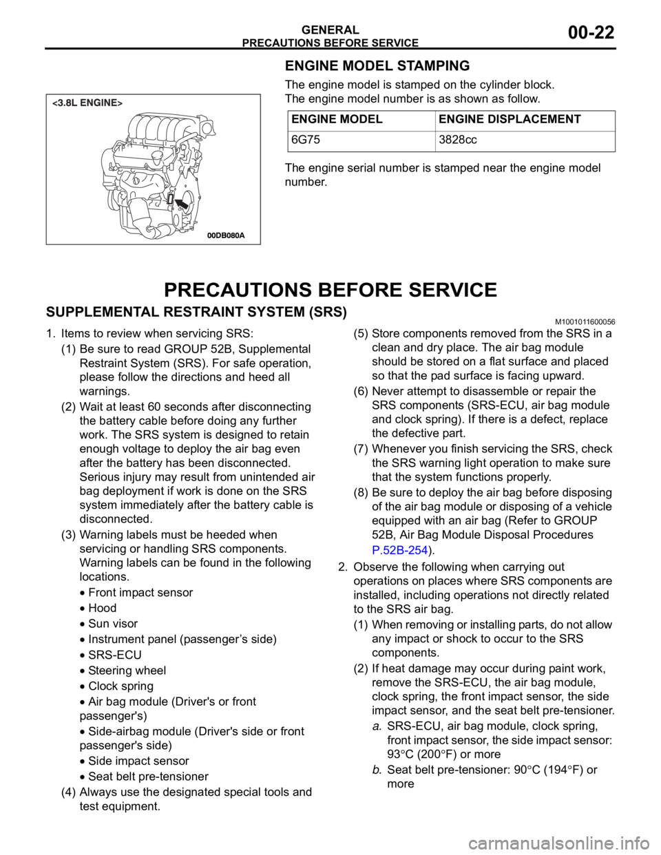
The engine model is stamped on the cylinder block.
The engine model number is as shown as follow.
The engine serial number is stamped near the engine model
number.
PRECAUTIONS BEFORE SERVICE
SUPPLEMENTAL RESTRAINT SYSTEM (SRS)M1001011600056
1. Items to review when servicing SRS:
(1) Be sure to read GROUP 52B, Supplemental
Restraint System (SRS). For safe operation,
please follow the directions and heed all
warnings.
(2) Wait at least 60 seconds after disconnecting
the battery cable before doing any further
work. The SRS system is designed to retain
enough voltage to deploy the air bag even
after the battery has been disconnected.
Serious injury may result from unintended air
bag deployment if work is done on the SRS
system immediately after the battery cable is
disconnected.
(3) Warning labels must be heeded when
servicing or handling SRS components.
Warning labels can be found in the following
locations.
Front impact sensor
Hood
Sun visor
Instrument panel (passenger ’s side)
SRS-ECU
Steering wheel
Clock spring
Air bag module (Driver's or front
passenger's)
Side-airbag module (Driver's side or front
passenger's side)
Side impact sensor
Seat belt pre-tensioner
(4) Always use the designated special tools and
test equipment.(5) Store components removed from the SRS in a
clean and dry place. The air bag module
should be stored on a flat surface and placed
so that the pad surface is facing upward.
(6) Never attempt to disassemble or repair the
SRS components (SRS-ECU, air bag module
and clock spring). If there is a defect, replace
the defective part.
(7) Whenever you finish servicing the SRS, check
the SRS warning light operation to make sure
that the system functions properly.
(8) Be sure to deploy the air bag before disposing
of the air bag module or disposing of a vehicle
equipped with an air bag (Refer to GROUP
52B, Air Bag Module Disposal Procedures
P.52B-254).
2. Observe the following when carrying out
operations on places where SRS components are
installed, including operations not directly related
to the SRS air bag.
(1) When removing or installing parts, do not allow
any impact or shock to occur to the SRS
components.
(2) If heat damage may occur during paint work,
remove the SRS-ECU, the air bag module,
clock spring, the front impact sensor, the side
impact sensor, and the seat belt pre-tensioner.
a.SRS-ECU, air bag module, clock spring,
front impact sensor, the side impact sensor:
93
C (200F) or more
b.Seat belt pre-tensioner: 90
C (194F) or
more ENGINE MODEL ENGINE DISPLACEMENT
6G75 3828cc
Page 1366 of 1500

AUTO-CRUISE CONTROL
ENGINE AND EMISSION CONTROL17-35
DTC 1571: Stoplamp Switch System
.
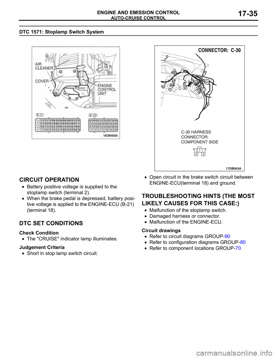
CIRCUIT OPERATION
Battery positive voltage is supplied to the
stoplamp switch (terminal 2).
When the brake pedal is depressed, battery posi-
tive voltage is applied to the ENGINE-ECU (B-21)
(terminal 18).
.
DTC SET CONDITIONS
Check Condition
The "CRUISE" indicator lamp illuminates.
Judgement Criteria
Short in stop lamp switch circuit.
Open circuit in the brake switch circuit between
ENGINE-ECU(terminal 18) and ground.
.
TROUBLESHOOTING HINTS (THE MOST
LIKELY CAUSES FOR THIS CASE:)
Malfunction of the stoplamp switch.
Damaged harness or connector.
Malfunction of the ENGINE-ECU.
Circuit drawings
Refer to circuit diagrams GROUP-90
Refer to configuration diagrams GROUP-80
Refer to component locations GROUP-70