brake sensor MITSUBISHI 380 2005 Workshop Manual
[x] Cancel search | Manufacturer: MITSUBISHI, Model Year: 2005, Model line: 380, Model: MITSUBISHI 380 2005Pages: 1500, PDF Size: 47.87 MB
Page 555 of 1500
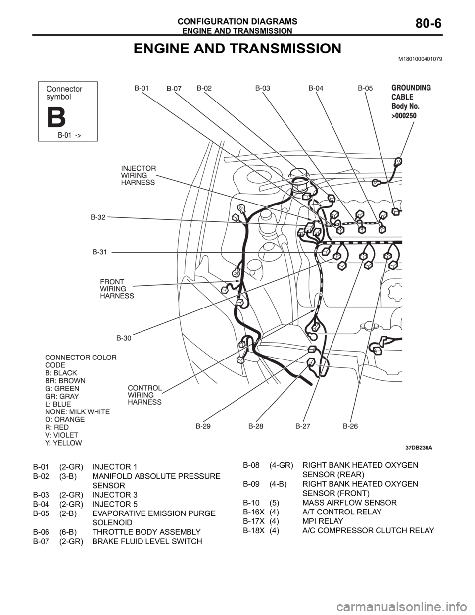
ENGINE AND TRANSMISSION
CONFIGURATION DIAGRAMS80-6
ENGINE AND TRANSMISSIONM1801000401079
B-01 (2-GR) INJECTOR 1
B-02 (3-B) MANIFOLD ABSOLUTE PRESSURE
SENSOR
B-03 (2-GR) INJECTOR 3
B-04 (2-GR) INJECTOR 5
B-05 (2-B) EVAPORATIVE EMISSION PURGE
SOLENOID
B-06 (6-B) THROTTLE BODY ASSEMBLY
B-07 (2-GR) BRAKE FLUID LEVEL SWITCHB-08 (4-GR) RIGHT BANK HEATED OXYGEN
SENSOR (REAR)
B-09 (4-B) RIGHT BANK HEATED OXYGEN
SENSOR (FRONT)
B-10 (5) MASS AIRFLOW SENSOR
B-16X (4) A/T CONTROL RELAY
B-17X (4) MPI RELAY
B-18X (4) A/C COMPRESSOR CLUTCH RELAY
Page 566 of 1500
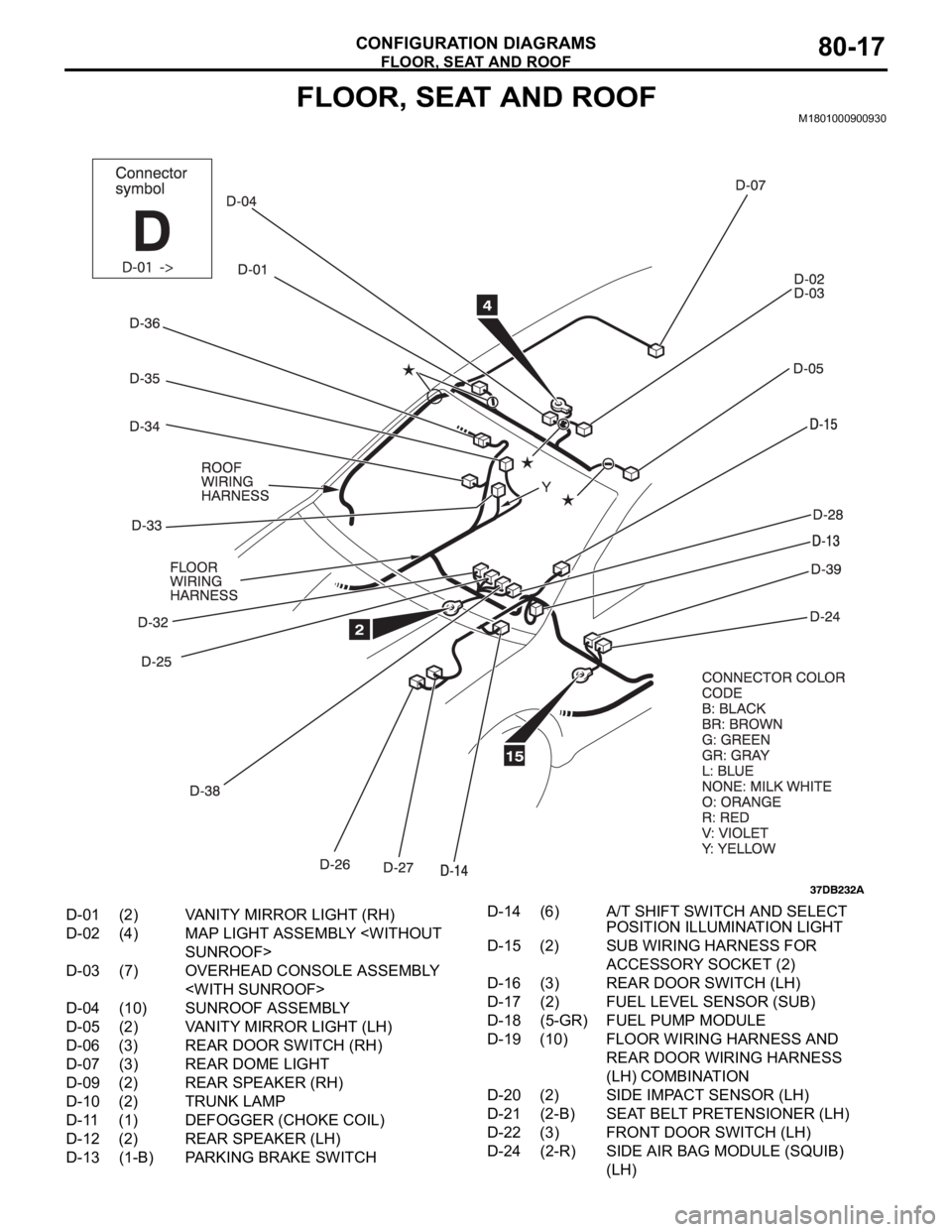
FLOOR, SEAT AND ROOF
CONFIGURATION DIAGRAMS80-17
FLOOR, SEAT AND ROOFM1801000900930
D-01 (2) VANITY MIRROR LIGHT (RH)
D-02 (4) MAP LIGHT ASSEMBLY
D-03 (7) OVERHEAD CONSOLE ASSEMBLY
D-04 (10) SUNROOF ASSEMBLY
D-05 (2) VANITY MIRROR LIGHT (LH)
D-06 (3) REAR DOOR SWITCH (RH)
D-07 (3) REAR DOME LIGHT
D-09 (2) REAR SPEAKER (RH)
D-10 (2) TRUNK LAMP
D-11 (1) DEFOGGER (CHOKE COIL)
D-12 (2) REAR SPEAKER (LH)
D-13 (1-B) PARKING BRAKE SWITCHD-14 (6) A/T SHIFT SWITCH AND SELECT
POSITION ILLUMINATION LIGHT
D-15 (2) SUB WIRING HARNESS FOR
ACCESSORY SOCKET (2)
D-16 (3) REAR DOOR SWITCH (LH)
D-17 (2) FUEL LEVEL SENSOR (SUB)
D-18 (5-GR) FUEL PUMP MODULE
D-19 (10) FLOOR WIRING HARNESS AND
REAR DOOR WIRING HARNESS
(LH) COMBINATION
D-20 (2) SIDE IMPACT SENSOR (LH)
D-21 (2-B) SEAT BELT PRETENSIONER (LH)
D-22 (3) FRONT DOOR SWITCH (LH)
D-24 (2-R) SIDE AIR BAG MODULE (SQUIB)
(LH)
Page 1166 of 1500
35A-1
GROUP 35A
BASIC BRAKE
SYSTEM
CONTENTS
GENERAL DESCRIPTION. . . . . . . . .35A-2
BASIC BRAKE SYSTEM DIAGNOSIS35A-3
INTRODUCTION TO BASIC BRAKE
SYSTEM DIAGNOSIS . . . . . . . . . . . . . . . . 35A-3
BASIC BRAKE SYSTEM DIAGNOSTIC
TROUBLESHOOTING STRATEGY . . . . . . 35A-3
SYMPTOM CHART. . . . . . . . . . . . . . . . . . . 35A-3
SYMPTOM PROCEDURES . . . . . . . . . . . . 35A-3
SPECIAL TOOLS . . . . . . . . . . . . . . . .35A-12
ON-VEHICLE SERVICE . . . . . . . . . . .35A-13
BRAKE PEDAL CHECK AND
ADJUSTMENT . . . . . . . . . . . . . . . . . . . . . . 35A-13
BRAKE BOOSTER OPERATING TEST . . . 35A-14
CHECK VALVE OPERATION CHECK . . . . 35A-15
BLEEDING . . . . . . . . . . . . . . . . . . . . . . . . . 35A-16
BRAKE FLUID LEVEL SENSOR CHECK. . 35A-17
DISC BRAKE PAD CHECK AND
REPLACEMENT . . . . . . . . . . . . . . . . . . . . . 35A-17
DISC BRAKE ROTOR CHECK . . . . . . . . . . 35A-19
MASTER CYLINDER FUNCTION CHECK . 35A-23
BRAKE PEDAL. . . . . . . . . . . . . . . . . .35A-24
REMOVAL AND INSTALLATION . . . . . . . . 35A-24
INSPECTION. . . . . . . . . . . . . . . . . . . . . . . . 35A-25
MASTER CYLINDER ASSEMBLY
AND BRAKE BOOSTER . . . . . . . . . .35A-26
REMOVAL AND INSTALLATION . . . . . . . . 35A-26
MASTER CYLINDER . . . . . . . . . . . . . . . . . 35A-28
INSPECTION. . . . . . . . . . . . . . . . . . . . . . . . 35A-29
DISC BRAKE ASSEMBLY . . . . . . . . .35A-30
REMOVAL AND INSTALLATION . . . . . . . . 35A-30
INSPECTION. . . . . . . . . . . . . . . . . . . . . . . . 35A-32
DISASSEMBLY AND ASSEMBLY
DISASSEMBLY AND ASSEMBLY
INSPECTION. . . . . . . . . . . . . . . . . . . . . . . . 35A-38
SPECIFICATIONS . . . . . . . . . . . . . . .35A-40
FASTENER TIGHTENING
SPECIFICATIONS. . . . . . . . . . . . . . . . . . . . 35A-40
GENERAL SPECIFICATIONS . . . . . . . . . . 35A-40
SERVICE SPECIFICATIONS . . . . . . . . . . . 35A-41
LUBRICANTS . . . . . . . . . . . . . . . . . . . . . . . 35A-41
Page 1182 of 1500
ON-VEHICLE SERVICE
BASIC BRAKE SYSTEM35A-17
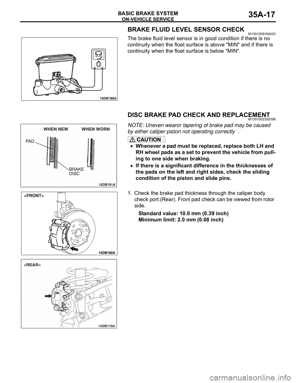
BRAKE FLUID LEVEL SENSOR CHECKM1351009100403
The brake fluid level sensor is in good condition if there is no
continuity when the float surface is above "MIN" and if there is
continuity when the float surface is below "MIN".
DISC BRAKE PAD CHECK AND REPLACEMENTM1351002300398
NOTE: Uneven wearor tapering of brake pad may be caused
by either caliper piston not operating correctly .
Whenever a pad must be replaced, replace both LH and
RH wheel pads as a set to prevent the vehicle from pull-
ing to one side when braking.
If there is a significant difference in the thicknesses of
the pads on the left and right sides, check the sliding
condition of the piston and slide pins.
1. Check the brake pad thickness through the caliper body
check port.(Rear). Front pad check can be viewed from rotor
side.
Standard value: 10.0 mm (0.39 inch)
Minimum limit: 2.0 mm (0.08 inch)
Page 1216 of 1500
PARKING BRAKE LINING AND DRUM
PARKING BRAKES36-9
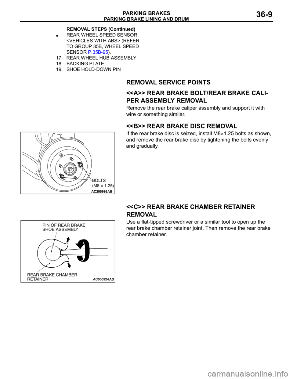
REMOVAL SERVICE POINTS
.
<> REAR BRAKE BOLT/REAR BRAKE CALI-
PER ASSEMBLY REMOVAL
Remove the rear brake caliper assembly and support it with
wire or something similar.
.
<> REAR BRAKE DISC REMOVAL
If the rear brake disc is seized, install M81.25 bolts as shown,
and remove the rear brake disc by tightening the bolts evenly
and gradually.
.
<
REMOVAL
Use a flat-tipped screwdriver or a similar tool to open up the
rear brake chamber retainer joint. Then remove the rear brake
chamber retainer.
REAR WHEEL SPEED SENSOR
TO GROUP 35B, WHEEL SPEED
SENSOR P.35B-95).
17. REAR WHEEL HUB ASSEMBLY
18. BACKING PLATE
19. SHOE HOLD-DOWN PIN
REMOVAL STEPS (Continued)
Page 1315 of 1500

TRACTION CONTROL SYSTEM (TCL) DIAGNOSIS
TRACTION CONTROL SYSTEM (TCL)13C-36
DATA LIST REFERENCE TABLEM1136003500071
NOTE: If the ABS-8 ECU or the active wheel
speed sensor are disconnected, or if the wiring is
an open/ short circuit, the ABS 8 ECU will shut
off power supply to the respective wheel speed
sensor. All other wheel speed sensors will oper-
ate normally. To restore the power supply, the
ignition switch must be turned to the "OFF" posi-
tion then to the "ON" position again.The following items can be read by the diagnostic
tool from the ABS/TCL-ECU input data. (Refer to
P.13C-3).
NOTE: Since the TCL is controlled with the same ABS/TCL-ECU used to control the ABS, the stoplight switch
check item (No.6) used only for the ABS also appear.MUT-III
DIAGNOSTI
C TOOL
DISPLAYITEM
NO.CHECK ITEM CHECKING REQUIREMENTS NORMAL
VA L U E
FL wheel
speed sensor01 Front left wheel speed sensor Drive the vehicle Vehicle speeds
displayed on the
speedometer
and diagnostic
tool are identical. FR wheel
speed sensor02 Front right wheel speed sensor
RL wheel
speed sensor03 Rear left wheel speed sensor
RR wheel
speed sensor04 Rear right left wheel speed
sensor
Power supply
voltage05 ABS/TCL-ECU power supply
voltageIgnition switch power supply
voltageBattery positive
voltage
Stoplamp
switch
(input)*06 Stoplamp switch Depress the brake pedal. ON
Release the brake pedal. OFF
Stoplamp
switch*13 Stoplamp switch Depress the brake pedal. ON
Release the brake pedal. OFF
Pump motor 21 Pump motor When the ABS outputs the
operation permission signal
during drivingON
When the ABS outputs the
operation permission signal
during drivingOFF
Valve relay 30 Valve relayWhen the ABS outputs the
operation permission signal
during drivingON
When the ABS outputs the
operation permission signal
during drivingOFF
TCL mode 35 TCL operation When the TCL outputs the
operation permission signal
during drivingON
When the TCL outputs the
operation inhibition signal
during drivingOFF
Page 1322 of 1500
TRACTION CONTROL SYSTEM (TCL) DIAGNOSIS
TRACTION CONTROL SYSTEM (TCL)13C-43
(7) The recommended Supply Voltage at terminals 16, 9, 6,
and 8 are:
Set value: 10.0Volts - 14.5Volts
Q: Is the supply voltage within the set value?
YES : Check wheel speed sensor signal at ABS-ECU using
an oscillopscope
NO :
Refer to Power supply systemP.35B-63
Refer to Motor supply systemP.35B-48
Refer to Valve relay systemP.35B-56
Measure wheel speed sensor signals using an
oscilloscope.
NOTE: To check connections of the wheel speed sensors,
remove the rear seat to access the rear wheel speed sen-
sor connectors, and remove inner front guard (splash
shield) to access the front wheel speed sensors.
(1) Wheel speed sensor must remain connected to measure
active sensor.
(2) ABS-ECU must remain connected.
(3) Remove ABS connector protection cap to access terminal
location from the rear of connector for back-probing.
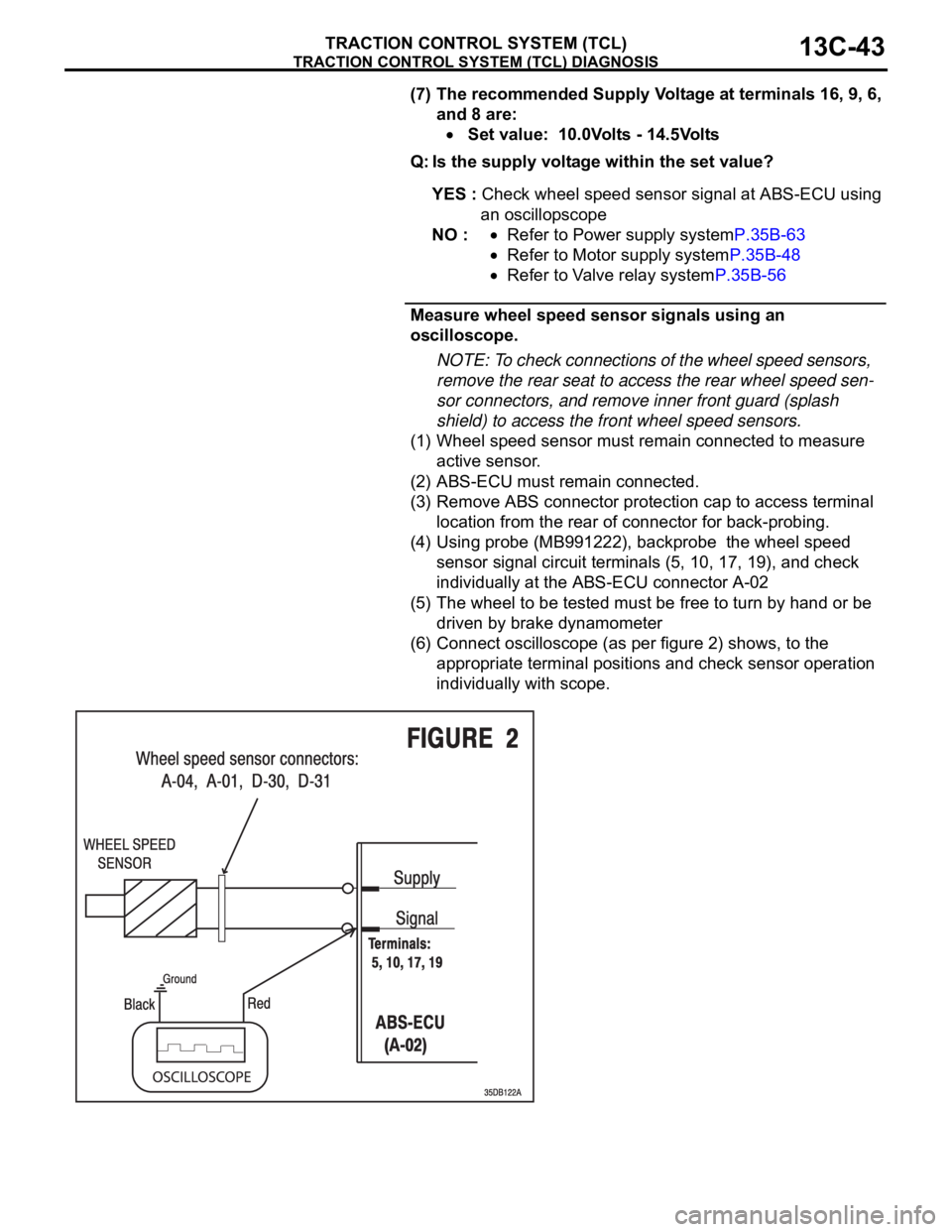
(4) Using probe (MB991222), backprobe the wheel speed
sensor signal circuit terminals (5, 10, 17, 19), and check
individually at the ABS-ECU connector A-02
(5) The wheel to be tested must be free to turn by hand or be
driven by brake dynamometer
(6) Connect oscilloscope (as per figure 2) shows, to the
appropriate terminal positions and check sensor operation
individually with scope.
Page 1323 of 1500
TRACTION CONTROL SYSTEM (TCL) DIAGNOSIS
TRACTION CONTROL SYSTEM (TCL)13C-44
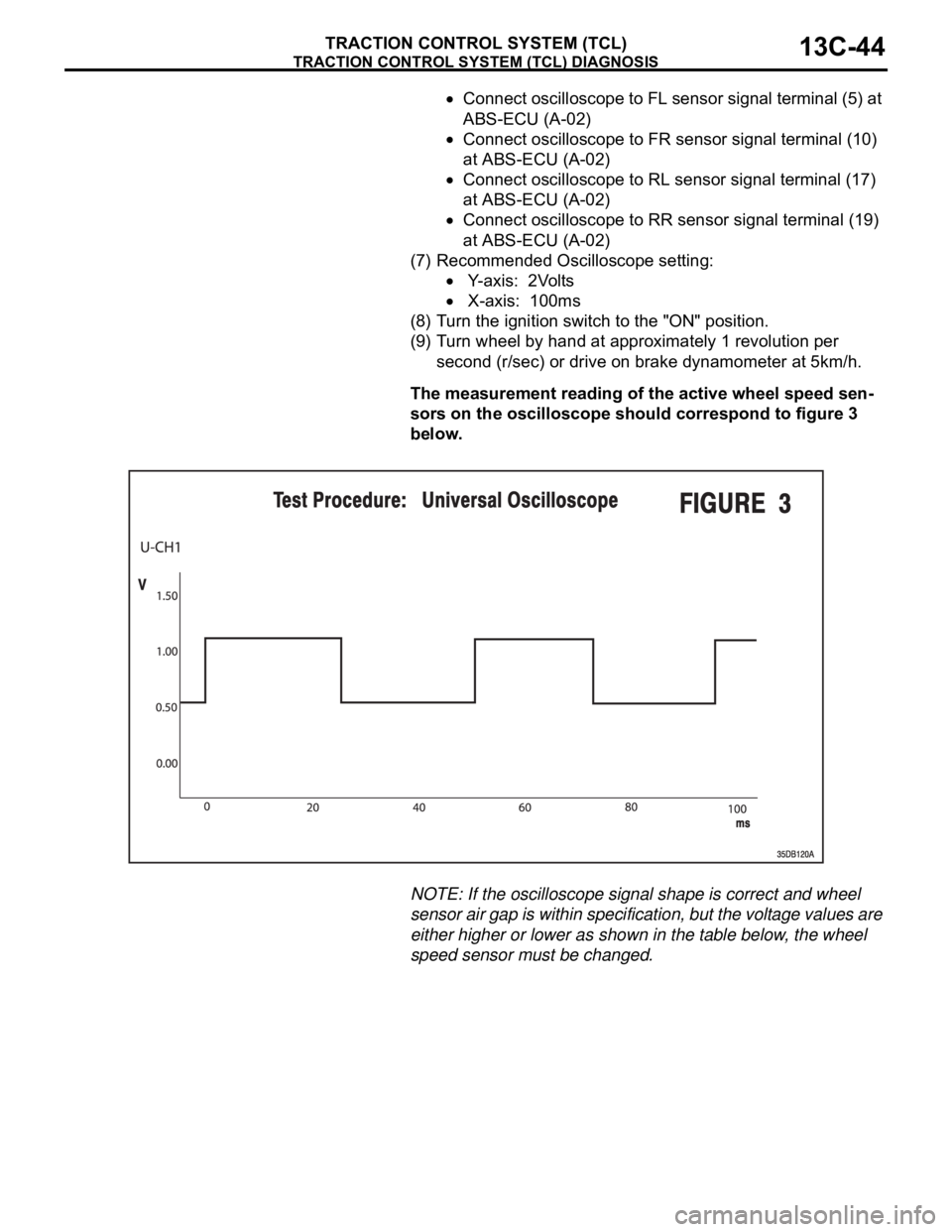
Connect oscilloscope to FL sensor signal terminal (5) at
ABS-ECU (A-02)
Connect oscilloscope to FR sensor signal terminal (10)
at ABS-ECU (A-02)
Connect oscilloscope to RL sensor signal terminal (17)
at ABS-ECU (A-02)
Connect oscilloscope to RR sensor signal terminal (19)
at ABS-ECU (A-02)
(7) Recommended Oscilloscope setting:
Y-axis: 2Volts
X-axis: 100ms
(8) Turn the ignition switch to the "ON" position.
(9) Turn wheel by hand at approximately 1 revolution per
second (r/sec) or drive on brake dynamometer at 5km/h.
The measurement reading of the active wheel speed sen-
sors on the oscilloscope should correspond to figure 3
below.
NOTE: If the oscilloscope signal shape is correct and wheel
sensor air gap is within specification, but the voltage values are
either higher or lower as shown in the table below, the wheel
speed sensor must be changed.
Page 1396 of 1500

AUTO-CRUISE CONTROL
ENGINE AND EMISSION CONTROL17-65
DATA LIST REFERENCE TABLE - Auto Cruise ControlM1172002400471
When shifting the selector lever to "D" range, apply the brakes so that the vehicle does not move
forward.
Driving tests always need two persons: one driver and one observer.
NOTE: *:After the inspection is completed, disconnect the throttle position sensor connector, and then delete
the diagnostic trouble code using use of Diagnostic Tool MB991958. (Refer to P.17-11).
MUT-III
Diagnostic
To o l
DISPLAYITEM
NO.INSPECTION ITEM INSPECTION REQUIREMENT NORMAL
CONDITION
APS
SNS(MAIN)11 A c c e l e r a t o r p e d a l
position sensor (main)Ignition
switch:
"ON"Accelerator pedal: Released
435
1,035 mV
Accelerator pedal: Gradually
depressedIncreases in
response to the
pedal depression
stroke
Accelerator pedal: Fully
depressed4,000 mV or more
BRAKE SW 89 Stoplamp switch Brake pedal: Depressed ON
Brake pedal: Released OFF
CANCEL
CODE57 Cancel code Ignition switch: "ON" The cancel code,
which set when the
auto-cruise control
system was
cancelled at the
last time, is set
again.
CANCEL
SWITCH75 Auto-cruise
control
switchCANCEL "CANCEL" switch: ON ON
"CANCEL" switch: OFF OFF
CLUTCH SW 78 Transmission inhibitor
switchTransmission inhibitor switch: "P" or
"N"ON
Transmission inhibitor switch: Other
than aboveOFF
CRUISE 81 Auto-cruise control
system operationAuto-cruise control system: active ON
Auto-cruise control system: Inactive OFF
MAIN SW 86 Auto-cruise
control
switchCRUISE
(MAIN)"CRUISE" (MAIN) switch: "ON" ON
"CRUISE" (MAIN) switch: "OFF" OFF
RESUME
SWITCH91 Auto-cruise
control
switchACC/RES "ACC/RES" switch: ON ON
"ACC/RES" switch: OFF OFF
SET SWITCH 92 Auto-cruise
control
switchCOAST/S
ET"COAST/SET" switch: ON ON
"COAST/SET" switch: OFF OFF
STOPLIGHT
SW74 Stoplamp switch Brake pedal: Depressed ON
Brake pedal: Released OFF
Page 1398 of 1500
AUTO-CRUISE CONTROL
ENGINE AND EMISSION CONTROL17-67
ENGINE ECU TERMINAL VOLTAGE REFERENCE CHART FOR AUTO-CRUISE
CONTROL SYSTEM OPERATION
M1172004800055
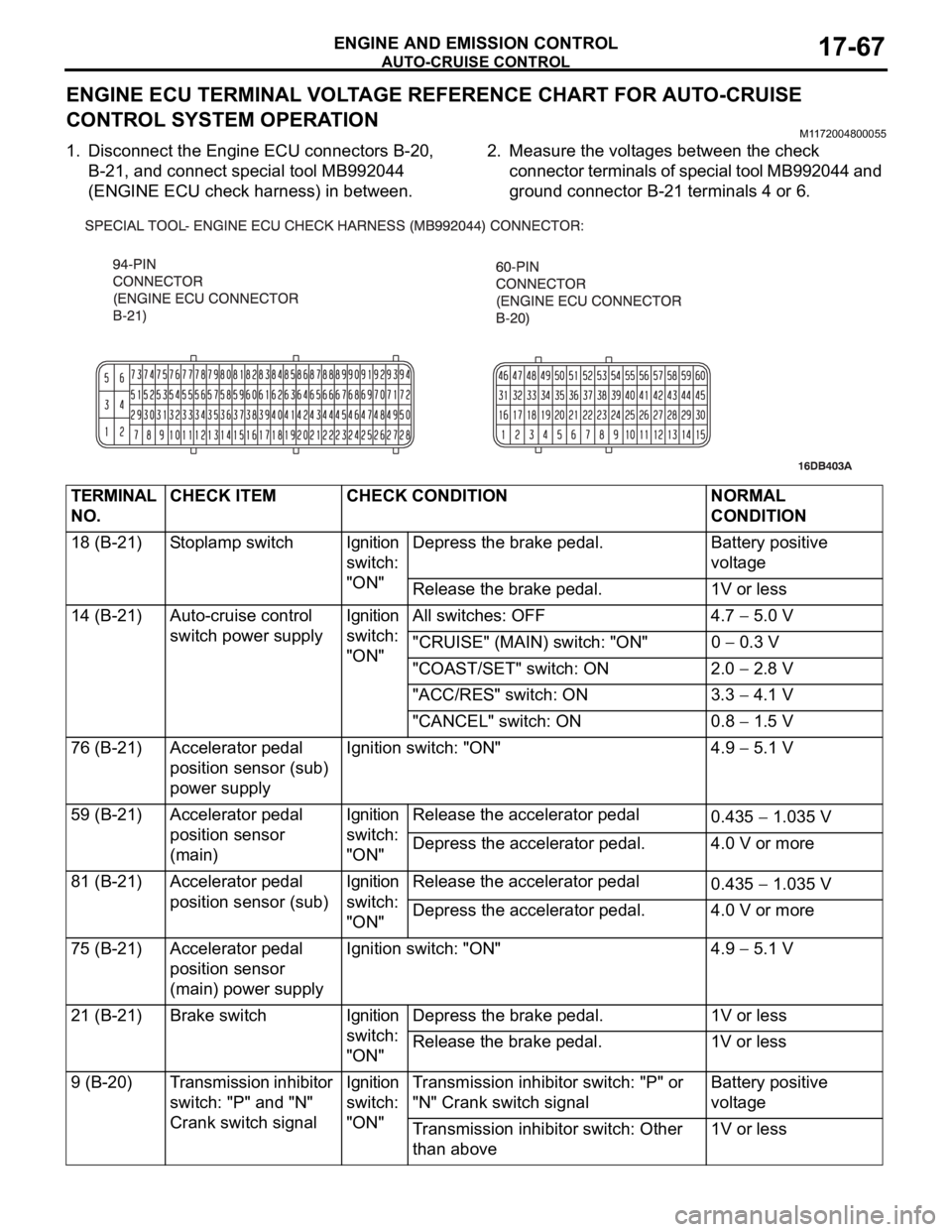
1. Disconnect the Engine ECU connectors B-20,
B-21, and connect special tool MB992044
(ENGINE ECU check harness) in between.2. Measure the voltages between the check
connector terminals of special tool MB992044 and
ground connector B-21 terminals 4 or 6.
TERMINAL
NO.CHECK ITEM CHECK CONDITION NORMAL
CONDITION
18 (B-21) Stoplamp switch Ignition
switch:
"ON"Depress the brake pedal. Battery positive
voltage
Release the brake pedal. 1V or less
14 (B-21) Auto-cruise control
switch power supplyIgnition
switch:
"ON"All switches: OFF 4.7
5.0 V
"CRUISE" (MAIN) switch: "ON" 0
0.3 V
"COAST/SET" switch: ON 2.0
2.8 V
"ACC/RES" switch: ON 3.3
4.1 V
"CANCEL" switch: ON 0.8
1.5 V
76 (B-21) Accelerator pedal
position sensor (sub)
power supplyIgnition switch: "ON" 4.9
5.1 V
59 (B-21) Accelerator pedal
position sensor
(main)Ignition
switch:
"ON"Release the accelerator pedal
0.435
1.035 V
Depress the accelerator pedal. 4.0 V or more
81 (B-21) Accelerator pedal
position sensor (sub)Ignition
switch:
"ON"Release the accelerator pedal
0.435
1.035 V
Depress the accelerator pedal. 4.0 V or more
75 (B-21) Accelerator pedal
position sensor
(main) power supplyIgnition switch: "ON" 4.9
5.1 V
21 (B-21) Brake switch Ignition
switch:
"ON"Depress the brake pedal. 1V or less
Release the brake pedal. 1V or less
9 (B-20) Transmission inhibitor
switch: "P" and "N"
Crank switch signalIgnition
switch:
"ON"Transmission inhibitor switch: "P" or
"N" Crank switch signalBattery positive
voltage
Transmission inhibitor switch: Other
than above1V or less