brake sensor MITSUBISHI 380 2005 User Guide
[x] Cancel search | Manufacturer: MITSUBISHI, Model Year: 2005, Model line: 380, Model: MITSUBISHI 380 2005Pages: 1500, PDF Size: 47.87 MB
Page 1406 of 1500

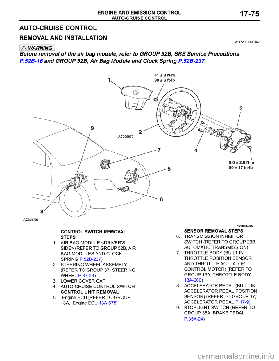
AUTO-CRUISE CONTROL
ENGINE AND EMISSION CONTROL17-75
AUTO-CRUISE CONTROL
REMOVAL AND INSTALLATIONM1172001400467
Before removal of the air bag module, refer to GROUP 52B, SRS Service Precautions
P.52B-16 and GROUP 52B, Air Bag Module and Clock Spring P.52B-237.
CONTROL SWITCH REMOVAL
STEPS
1. AIR BAG MODULE
BAG MODULES AND CLOCK
SPRING P.52B-237)
2. STEERING WHEEL ASSEMBLY
(REFER TO GROUP 37, STEERING
WHEEL P.37-23)
3. LOWER COVER CAP
4. AUTO-CRUISE CONTROL SWITCH
CONTROL UNIT REMOVAL
5. Engine ECU [REFER TO GROUP
13A, Engine ECU 13A-675] SENSOR REMOVAL STEPS
6. TRANSMISSION INHIBITOR
SWITCH (REFER TO GROUP 23B,
AUTOMATIC TRANSMISSION)
7. THROTTLE BODY (BUILT-IN
THROTTLE POSITION SENSOR
AND THROTTLE ACTUATOR
CONTROL MOTOR) (REFER TO
GROUP 13A, THROTTLE BODY
13A-660)
8. ACCELERATOR PEDAL (BUILT-IN
ACCELERATOR PEDAL POSITION
SENSOR) (REFER TO GROUP 17,
ACCELERATOR PEDAL P.17-9)
9. STOPLIGHT SWITCH (REFER TO
GROUP 35A, BRAKE PEDAL
P.35A-24)
Page 1426 of 1500

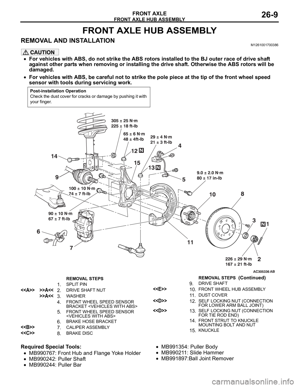
FRONT AXLE HUB ASSEMBLY
FRONT AXLE26-9
FRONT AXLE HUB ASSEMBLY
REMOVAL AND INSTALLATIONM1261001700386
For vehicles with ABS, do not strike the ABS rotors installed to the BJ outer race of drive shaft
against other parts when removing or installing the drive shaft. Otherwise the ABS rotors will be
damaged.
For vehicles with ABS, be careful not to strike the pole piece at the tip of the front wheel speed
sensor with tools during servicing work.
Required Special Tools:
MB990767: Front Hub and Flange Yoke Holder
MB990242: Puller Shaft
MB990244: Puller Bar
MB991354: Puller Body
MB990211: Slide Hammer
MB991897:Ball Joint Remover
Post-installation Operation
Check the dust cover for cracks or damage by pushing it with
your finger.
REMOVAL STEPS
1. SPLIT PIN
<> >>A<<2. DRIVE SHAFT NUT
>>A<<3. WASHER
4. FRONT WHEEL SPEED SENSOR
BRACKET
5. FRONT WHEEL SPEED SENSOR
6. BRAKE HOSE BRACKET
<> 7. CALIPER ASSEMBLY
<
9. DRIVE SHAFT
<
11 .DUST COVER
<
FOR LOWER ARM BALL JOINT)
<
FOR TIE ROD END)
14.FRONT STRUT TO KNUCKLE
MOUNTING BOLT AND NUT
15.KNUCKLE
REMOVAL STEPS (Continued)
Page 1431 of 1500

DRIVE SHAFT ASSEMBLY
FRONT AXLE26-14
Required Special Tools:
MB990767: Front Hub and Flange Yoke Holder
MB991897: Ball Joint Remover
MB990242: Puller Shaft Puller
MB990244: Puller Bar
MB991354: Puller Body
MB990998: Front Hub Remover and Installer
MB991000: Spacer
REMOVAL STEPS
1. SPLIT PIN
<> >>B<<2. DRIVE SHAFT NUT
3. WASHER
4. FRONT WHEEL SPEED SENSOR
BRACKET
5. FRONT WHEEL SPEED SENSOR
6. BRAKE HOSE BRACKET
<>7. SELF LOCKING NUT (LOWER
ARM BALL JOINT CONNECTION)
<>8. SELF LOCKING NUT (TIE ROD
END CONNECTION)
<
<
SHAFT ASSEMBLY RH
11. CIRCLIPREMOVAL STEPS (Continued)
Page 1453 of 1500

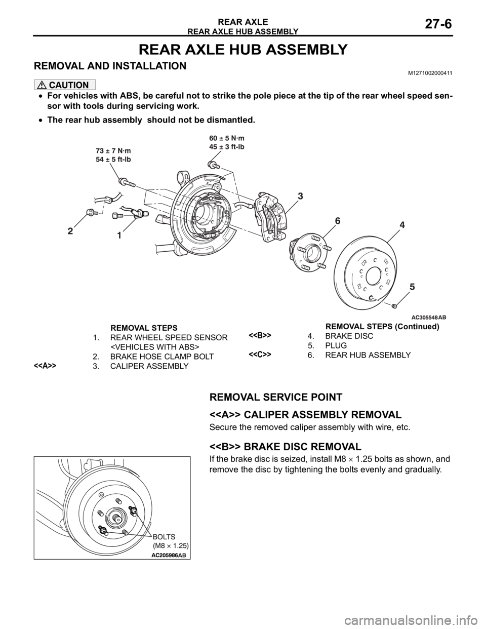
REAR AXLE HUB ASSEMBLY
REAR AXLE27-6
REAR AXLE HUB ASSEMBLY
REMOVAL AND INSTALLATIONM1271002000411
For vehicles with ABS, be careful not to strike the pole piece at the tip of the rear wheel speed sen-
sor with tools during servicing work.
The rear hub assembly should not be dismantled.
REMOVAL SERVICE POINT
.
<> CALIPER ASSEMBLY REMOVAL
Secure the removed caliper assembly with wire, etc.
.
<> BRAKE DISC REMOVAL
If the brake disc is seized, install M8 1.25 bolts as shown, and
remove the disc by tightening the bolts evenly and gradually.
.
REMOVAL STEPS
1. REAR WHEEL SPEED SENSOR
2. BRAKE HOSE CLAMP BOLT
<>3. CALIPER ASSEMBLY
<>4. BRAKE DISC
5. PLUG
<
Page 1478 of 1500

AUTOMATIC TRANSMISSION DIAGNOSIS
AUTOMATIC TRANSMISSION23A-19
ROAD TESTM1231007800407
Check using the following procedures.
STEP CONDITION
BEFORE
TEST/OPERATIONTEST/OPERATION STANDARD INSPECTION
ITEMINSPECTION
PROCEDURE
PA G E
1 Ignition switch:
(LOCK) OFFIgnition switch
(1) ONData list No.8
(1) Control Relay
Voltage [V]A/T Control
relay
output
voltageA/T Control
relay system
(P.23A-207).
2 Ignition switch:
ON
Engine: Stopped
Transmission
range: PTransmission range
(1) P, (2) R, (3) N, (4)
DData list No.34
(1) P, (2) R, (3) N, (4)
DTransmissi
on range
switchTransmission
range switch
system
(P.23A-97,
P.23A-119).
Transmission range
(1) D (1st gear)
(2) Select the sport
mode (1st gear)
(3) Upshift and hold
the selector lever in
that position (2nd
gear)
(4) Downshift and
hold the selector
lever in that position
(1st gear)Data list No.27
(1) OFF, (2) ON, (3)
ON, (4) ON
Data list No.28
(1) OFF, (2) OFF, (3)
ON, (4) OFF
Data list No.29
(1) OFF, (2) OFF, (3)
OFF, (4) ONSelect
switch and
Shift switchShift switch
assembly
system
(P.23A-252).
Brake pedal
(1) Depressed
(2) ReleasedData list No.19
(1) ON
(2) OFFSto pl amp
switchSt o pla mp
switch system
(P.23A-89).
3 Ignition switch:
ST
Engine: StoppedCranking test with
lever in P or N rangeCranking should be
possibleCranking Engine does
not crank
(P.23A-218).
4 Engine warming
upDrive for 15 minutes
or more so that the
transmission fluid
temperature
becomes 70
90CData list No.7
Gradually rises to 70
90CTransmissi
on fluid
temperatur
e sensorTransmission
fluid
temperature
sensor system
(P.23A-36,
P.23A-47).
5 Engine: Idling
Transmission
range: NBrake pedal (Retest)
(1) Depressed
(2) ReleasedData list No.19
(1) ON
(2) OFFSto pl amp
switchSt o pla mp
switch system
(P.23A-89).
Transmission range
(1) N
D
(2) N
RShould be no
abnormal shift
shocks
Time delay when
engaging should be
within 2 secondsMalfunction
when
startingEngine stalls
when moving
selector lever
from N to D or
N to R
(P.23A-227).
Page 1484 of 1500

AUTOMATIC TRANSMISSION DIAGNOSIS
AUTOMATIC TRANSMISSION23A-25
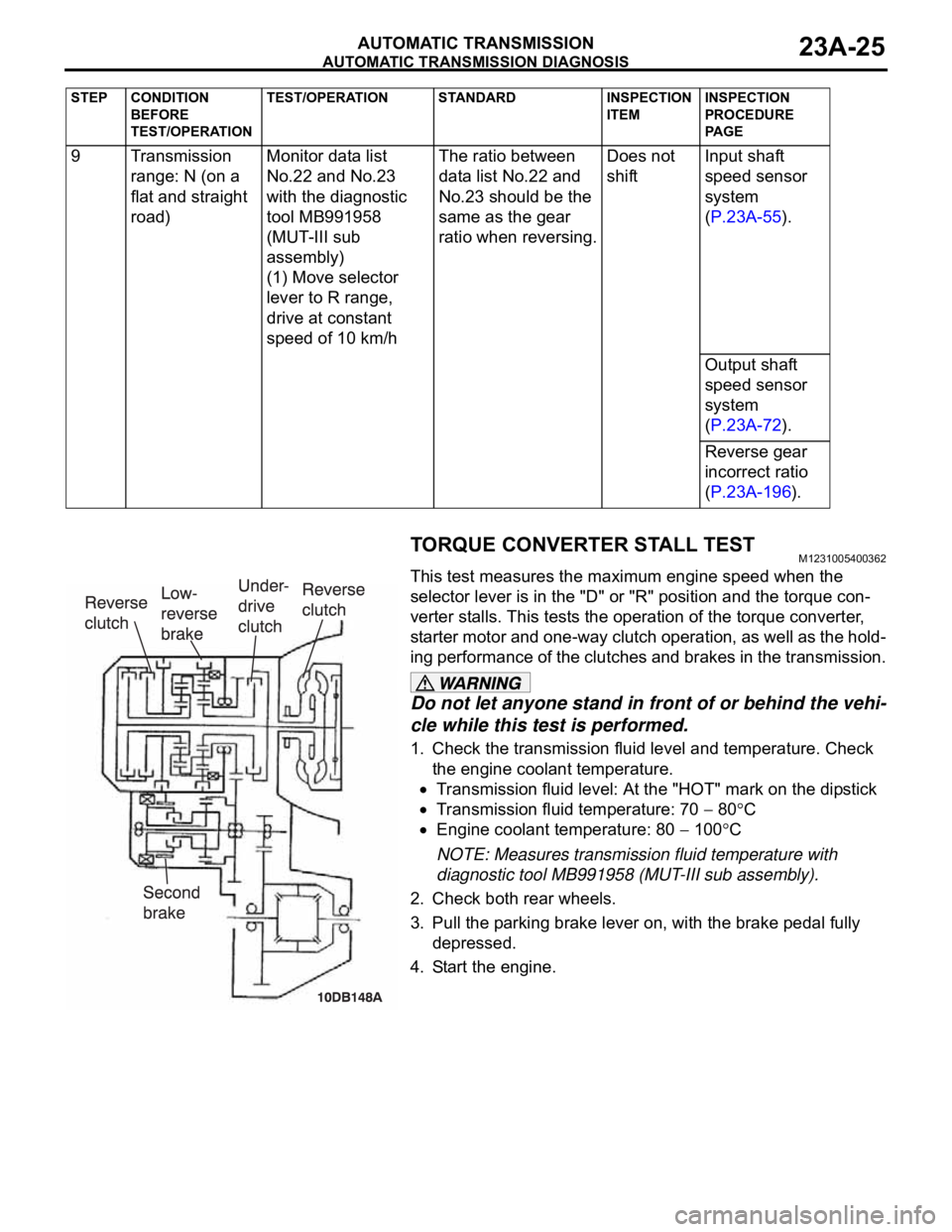
TORQUE CONVERTER STALL TESTM1231005400362
This test measures the maximum engine speed when the
selector lever is in the "D" or "R" position and the torque con-
verter stalls. This tests the operation of the torque converter,
starter motor and one-way clutch operation, as well as the hold-
ing performance of the clutches and brakes in the transmission.
Do not let anyone stand in front of or behind the vehi-
cle while this test is performed.
1. Check the transmission fluid level and temperature. Check
the engine coolant temperature.
Transmission fluid level: At the "HOT" mark on the dipstick
Transmission fluid temperature: 70 80C
Engine coolant temperature: 80 100C
NOTE: Measures transmission fluid temperature with
diagnostic tool MB991958 (MUT-III sub assembly).
2. Check both rear wheels.
3. Pull the parking brake lever on, with the brake pedal fully
depressed.
4. Start the engine. 9 Transmission
range: N (on a
flat and straight
road)Monitor data list
No.22 and No.23
with the diagnostic
tool MB991958
(MUT-III sub
assembly)
(1) Move selector
lever to R range,
drive at constant
speed of 10 km/hThe ratio between
data list No.22 and
No.23 should be the
same as the gear
ratio when reversing.Does not
shiftInput shaft
speed sensor
system
(P.23A-55).
Output shaft
speed sensor
system
(P.23A-72).
Reverse gear
incorrect ratio
(P.23A-196).
STEP CONDITION
BEFORE
TEST/OPERATIONTEST/OPERATION STANDARD INSPECTION
ITEMINSPECTION
PROCEDURE
PA G E