lock MITSUBISHI ASX 2015 Owner's Manual (in English)
[x] Cancel search | Manufacturer: MITSUBISHI, Model Year: 2015, Model line: ASX, Model: MITSUBISHI ASX 2015Pages: 452, PDF Size: 20.1 MB
Page 3 of 452
Table of contents
Overview
1
General information
2
Locking and unlocking
3
Seat and seat belts
4
Instruments and controls
5
Starting and driving
6
For pleasant driving
7
For emergencies
8
Vehicle care
9
Maintenance
10
Specifications
11
Alphabetical index
12
Declaration of Conformity
13
OGAE15E5
Page 8 of 452
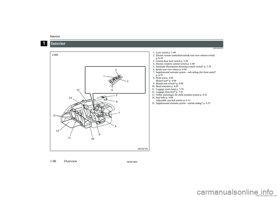
InteriorE001002062531. Lock switch p. 3-402. Electric remote-controlled outside rear-view mirrors switch p. 6-10
3. Central door lock switch p. 3-26
4. Electric window control switch p. 3-40
5. Sunshade illumination dimming control switch* p. 7-76
6. Inside rear-view mirror p. 6-08
7. Supplemental restraint system - side airbag (for front seats)* p. 4-33
8. Front seat p. 4-03 Heated seat* p. 4-06
9. Heated seat switch* p. 4-06
10. Head restraints p. 4-07
11. Luggage room lamp p. 7-76
12. Luggage floor box* p. 7-81
13. Tether anchorages for child restraint system p. 4-22
14. Seat belts p. 4-09 Adjustable seat belt anchor p. 4-11
15. Supplemental restraint system - curtain airbag* p. 4-33
Interior
1-06OGAE15E5Overview1LHD
Page 10 of 452
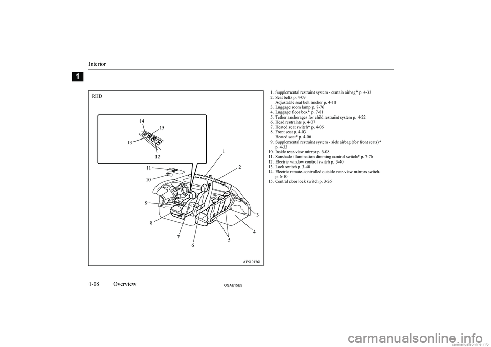
1. Supplemental restraint system - curtain airbag* p. 4-33
2. Seat belts p. 4-09 Adjustable seat belt anchor p. 4-11
3. Luggage room lamp p. 7-76
4. Luggage floor box* p. 7-81
5. Tether anchorages for child restraint system p. 4-22
6. Head restraints p. 4-07
7. Heated seat switch* p. 4-06
8. Front seat p. 4-03 Heated seat* p. 4-06
9. Supplemental restraint system - side airbag (for front seats)* p. 4-33
10. Inside rear-view mirror p. 6-08
11. Sunshade illumination dimming control switch* p. 7-76
12. Electric window control switch p. 3-40
13. Lock switch p. 3-40
14. Electric remote-controlled outside rear-view mirrors switch p. 6-10
15. Central door lock switch p. 3-26
Interior
1-08OGAE15E5Overview1RHD
Page 15 of 452
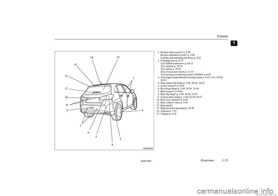
1. Keyless entry system* p. 3-04Keyless operation system* p. 3-08
Locking and unlocking the doors p. 3-25
2. Changing tyres p. 8-13 Tyre inflation pressures p. 10-13
Tyre rotation p. 10-15
Tyre chains p. 10-16
Size of tyres and wheels p. 11-13
Tyre pressure monitoring system (TPMS)* p. 6-59
3. Turn-signal lamps/Hazard warning lamps p. 5-55, 5-55, 10-26, 10-35
4. Stop lamps/Tail lamps p. 5-48, 10-26, 10-35
5. Corner sensors* p. 6-65
6. Reversing lamps p. 5-48, 10-26, 10-36
7. Back sensors* p. 6-64
8. Rear fog lamp* p. 5-56, 10-26, 10-34
9. Licence plate lamps p. 5-48, 10-26, 10-37
10. Rear-view camera* p. 6-68
11. Rear window wiper p. 5-61
12. Rear spoiler
13. High-mounted stop lamp p. 10-26
14. Antenna p. 7-47
15. Tailgate p. 3-30
Exterior
1-13OGAE15E5Overview112
3
4
5
6
7
8
9
10 11
12
13
14
15
Page 20 of 452
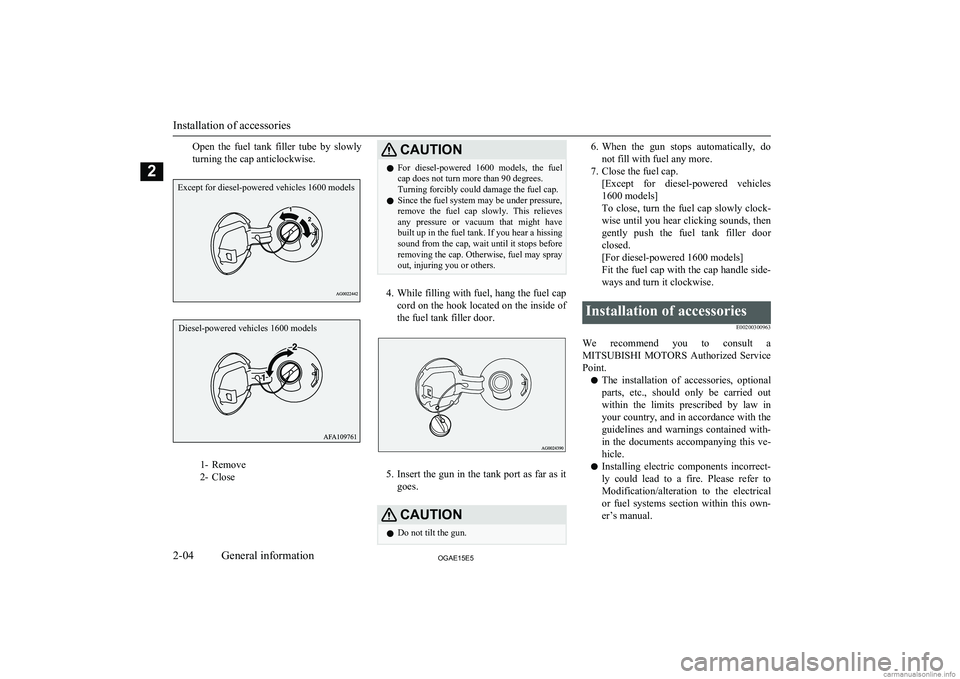
Open the fuel tank filler tube by slowly
turning the cap anticlockwise.
1- Remove
2- Close
CAUTIONl For diesel-powered 1600 models, the fuel
cap does not turn more than 90 degrees.
Turning forcibly could damage the fuel cap.
l Since the fuel system may be under pressure,
remove the fuel cap slowly. This relieves
any pressure or vacuum that might have built up in the fuel tank. If you hear a hissingsound from the cap, wait until it stops before
removing the cap. Otherwise, fuel may spray
out, injuring you or others.
4. While filling with fuel, hang the fuel cap
cord on the hook located on the inside of
the fuel tank filler door.
5. Insert the gun in the tank port as far as it
goes.
CAUTIONl Do not tilt the gun.6.
When the gun stops automatically, do
not fill with fuel any more.
7. Close the fuel cap. [Except for diesel-powered vehicles
1600 models]
To close, turn the fuel cap slowly clock-
wise until you hear clicking sounds, then
gently push the fuel tank filler door closed.
[For diesel-powered 1600 models]
Fit the fuel cap with the cap handle side-
ways and turn it clockwise.Installation of accessories
E00200300963
We recommend you to consult aMITSUBISHI MOTORS Authorized Service
Point.
l The installation of accessories, optional
parts, etc., should only be carried out
within the limits prescribed by law in your country, and in accordance with the
guidelines and warnings contained with-
in the documents accompanying this ve- hicle.
l Installing electric components incorrect-
ly could lead to a fire. Please refer to Modification/alteration to the electrical
or fuel systems section within this own- er’s manual.
Installation of accessories
2-04OGAE15E5General information2Except for diesel-powered vehicles 1600 models Diesel-powered vehicles 1600 models
Page 25 of 452
Keys.................................................................................................... 3-02Electronic immobilizer (Anti-theft starting system)........................... 3-03
Keyless entry system*.........................................................................3-04
Keyless operation system*.................................................................. 3-08
Doors................................................................................................... 3-25
Central door locks............................................................................... 3-26
Dead Lock System*............................................................................ 3-27
“Child-protection” rear doors..............................................................3-30
Tailgate................................................................................................3-30
Inside tailgate release.......................................................................... 3-31
Security alarm system*....................................................................... 3-32
Electric window control...................................................................... 3-39
Sunshade*........................................................................................... 3-41Locking and unlocking
OGAE15E53
Page 26 of 452
KeysE00300102269
Type 1
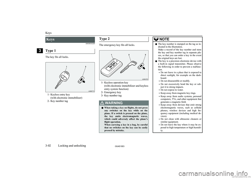
The key fits all locks.
1- Keyless entry key (with electronic immobilizer)
2- Key number tag
Type 2
The emergency key fits all locks.
1- Keyless operation key (with electronic immobilizer and keyless
entry system function)
2- Emergency key
3- Key number tag
WARNINGl When taking a key on flights, do not press
any switches on the key while on the
plane. If a switch is pressed on the plane, the key emits electromagnetic waves,which could adversely affect the plane’s
flight operation.
When carrying a key in a bag, be careful that no switches on the key can be easily
pressed by mistake.NOTEl The key number is stamped on the tag as in-
dicated in the illustration.
Make a record of the key number and store the key and key number tag in separate pla-
ces, so that you can order a key in the event the original keys are lost.
l The key is a precision electronic device with
a built-in signal transmitter. Please observe the following in order to prevent a malfunc-tion.
• Do not leave in a place that is exposed to
direct sunlight, for example on the dash- board.
• Do not disassemble or modify.
• Do not excessively bend the key or sub-
ject it to strong impacts.
• Do not expose to water.
• Keep away from magnetic key rings.
• Keep away from audio systems, personal
computers, TVs, and other equipment that generates a magnetic field.
• Keep away from devices that emit strong
electromagnetic waves, such as cellular phones, wireless devices and high fre-quency equipment (including medical de-
vices).
• Do not clean with ultrasonic cleaners or
similar equipment.
• Do not leave the key where it may be ex-
posed to high temperature or high humidi-ty.
Keys
3-02OGAE15E5Locking and unlocking3
Page 27 of 452
NOTElThe engine is designed so that it will not
start if the ID code registered in the immo- bilizer computer and the key’s ID code do
not match. Refer to the “Electronic immobil-
izer” section for details and key usage.
l [For vehicles equipped with the security
alarm system]
Pay attention to the following if the security alarm is set to “Active”.
Refer to “Security alarm system” on page
3-32.
• If the security alarm is in the system
armed mode, the alarm will sound if the doors are opened after being unlocked
with the key, the inside lock knob or the
central door lock switch.
• Even if the security alarm is set to “Ac-
tive”, the system preparation mode is not
entered if the keyless entry system or the keyless operation function was not used to
lock the vehicle.Electronic immobilizer
(Anti-theft starting system) E00300203078
[For vehicles equipped with keyless opera-tion system]
For information on operations for vehicles equipped with the keyless operation system,
refer to “Keyless operation system: Electron- ic immobilizer (Anti-theft starting system)”
on page 3-13.
[Except vehicles equipped with keyless oper-
ation system]
The electronic immobilizer is designed to significantly reduce the possibility of vehicle
theft. The purpose of the system is to immo-
bilize the vehicle if an invalid start is attemp-
ted. A valid start attempt can only be ach- ieved by using a key “registered” to the im-mobilizer system.NOTEl In the following cases, the vehicle may not
be able to receive the registered ID code from the registered key and the engine may
not start.
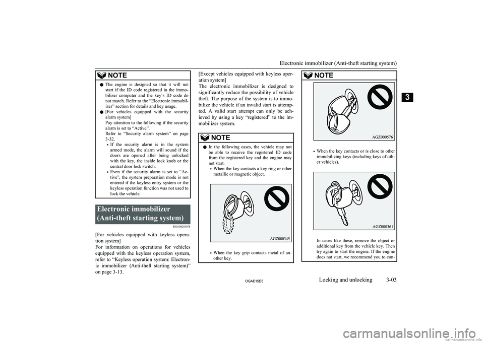
• When the key contacts a key ring or other
metallic or magnetic object.
• When the key grip contacts metal of an-
other key.
NOTE
• When the key contacts or is close to other
immobilizing keys (including keys of oth-er vehicles).
In cases like these, remove the object or additional key from the vehicle key. Then
try again to start the engine. If the engine
does not start, we recommend you to con-
Electronic immobilizer (Anti-theft starting system)
3-03OGAE15E5Locking and unlocking3
Page 28 of 452
NOTEtact your MITSUBISHI MOTORS Au-
thorized Service Point.
l If you lose one of them, contact a
MITSUBISHI MOTORS Authorized Serv-
ice Point as soon as possible. To obtain a re-
placement or extra spare key, take your vehi-
cle and all remaining keys to your MITSUBISHI MOTORS Authorized Serv-
ice Point. All the keys have to be re-regis- tered in the immobilizer computer unit. The
immobilizer can register up to 8 different
keys.CAUTIONl Do not modify or add parts to the immobiliz-
er system. Doing so could cause the immo- bilizer to malfunction.Keyless entry system*
E00300302649
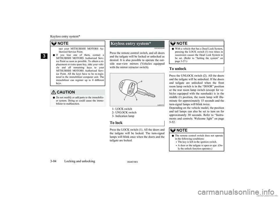
Press the remote control switch, and all doors and the tailgate will be locked or unlocked as
desired. It is also possible to operate the out-
side rear-view mirrors (Vehicles equipped with the mirror retractor switch).
1- LOCK switch
2- UNLOCK switch
3- Indication lamp
To lock
Press the LOCK switch (1). All the doors and the tailgate will be locked. The turn-signal
lamps will blink once when the doors and the
tailgate are locked.
NOTEl With a vehicle that has a Dead Lock System,
pressing the LOCK switch (1) two times in
succession causes the Dead Lock System to be set. (Refer to “Setting the system” on
page 3-27.)
To unlock
Press the UNLOCK switch (2). All the doors
and the tailgate will be unlocked. If the doors and tailgate are unlocked when the frontroom lamp switch is in the “DOOR” positionor the rear room lamp switch (except for ve-
hicles equipped with the sunshade) is in the
middle (•) position, the room lamp will illu- minate for approximately 15 seconds and theturn-signal lamps will blink twice.
Depending on the vehicle model, the position
and tail lamps can also be set to turn on for
approximately 30 seconds. Refer to “Instru-
ments and controls: Welcome light” on page
5-52.
NOTEl The remote control switch does not operate
in the following conditions:
• The key is left in the ignition switch.
• A door or the tailgate is open or ajar. (On-
ly the unlock function operates.)
Keyless entry system*
3-04OGAE15E5Locking and unlocking3
Page 29 of 452
NOTElExcept for vehicles equipped with a Dead
Lock System, the door and tailgate unlock function can be set so that only the driver’sdoor unlocks when the UNLOCK switch (2) is pressed once.
If the door and tailgate unlock function is set
to work as described above, all the doors and the tailgate unlock when the UNLOCK
switch is pressed two times in succession.
Refer to “Setting of door and tailgate unlock function” on page 3-06.
l The indication lamp (3) comes on each time
a switch is pressed.
l For vehicles equipped with the mirror retrac-
tor switch, the outside rear-view mirrors au- tomatically retract or extend when all the
doors and tailgate are locked or unlocked us- ing the remote control switches of the key- less entry system.
Refer to “Starting and driving: Outside rear- view mirrors” on page 6-10.
l If the UNLOCK switch (2) is pressed and no
door or tailgate is opened within approxi-mately 30 seconds, relocking will automati-
cally occur.
l It is possible to modify functions as follows:
For further information, please contact your MITSUBISHI MOTORS Authorized Serv-
ice Point.
• The time for automatic relocking can be
changed.NOTE• The confirmation function (flashing of the
turn-signal lamps) can be set to operate
only when the doors and backdoor are locked or only when the doors and back- door are unlocked.
• The confirmation function (this indicates
locking or unlocking of the doors and tail-
gate with the flash of the turn-signal
lamps) can be deactivated.
• The number of times the turn-signal
lamps are flashed by the confirmation function can be changed.
Operation of the Dead Lock
System
In a vehicle that has a Dead Lock System, it
is possible to set the Dead Lock System using the remote controller.
(Refer to “Dead Lock System” on page 3-27.)
Operation of the outside rear-
view mirrors (Vehicles equip-ped with mirror retractorswitch)
E00310800236
To fold
Within 30 seconds of locking the doors and tailgate using the LOCK switch (1), press the LOCK switch twice rapidly to fold the out- side rear-view mirrors.
To extend
Within 30 seconds of unlocking the doors
and tailgate using the UNLOCK switch (2),
press the UNLOCK switch twice rapidly to
return the outside rear-view mirrors to their
extended positions.
The outside rear-view mirrors are not ini-
tially set to work as described above. If you
want them to work as described above, you need to set them so that they do not retract/ extend when the doors and tailgate are
locked/unlocked using the keyless entry sys-
tem or keyless operation system.
Refer to “Starting and driving: Outside rear-
view mirrors” on page 6-10.
For details, please consult a MITSUBISHI
MOTORS Authorized Service Point.
Keyless entry system*
3-05OGAE15E5Locking and unlocking3