oil filter MITSUBISHI COLT 2006 Service Repair Manual
[x] Cancel search | Manufacturer: MITSUBISHI, Model Year: 2006, Model line: COLT, Model: MITSUBISHI COLT 2006Pages: 364, PDF Size: 11.65 MB
Page 53 of 364
BASE ENGINE
ENGINE MECHANICAL <4A9>11A-5
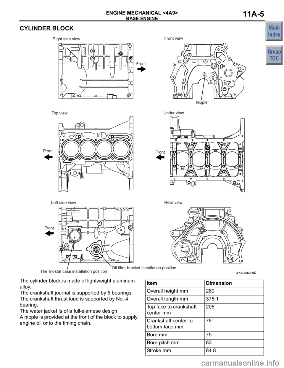
CYLINDER BLOCK
AK402339AC
Front view
Right side view
Under view
Top view
Rear view
Left side view
Thermostat case installation positionOil filter bracket installation position Front
Front Front Front
Nipple
The cylinder b
l ock is ma de of ligh twe i ght aluminum
allo
y .
The crankshaf t jo urnal is supp orted b y 5 b earing s .
The crankshaf
t thru st load is supporte d by No . 4
bearin
g.
The water jacket is of a full-siamese de sig n .
A nipple is p r ovid ed at the fr o n t of the block to su pply
engin
e oil onto the timin g ch ain.
ItemDimension
Overall height mm280
Overall length mm375.1
Top face to crankshaft
center mm205
Crankshaft center to
bottom face mm75
Bore mm75
Bore pitch mm83
Stroke mm84.8
Page 63 of 364
BASE ENGINE
ENGINE MECHANICAL <4A9>11A-15
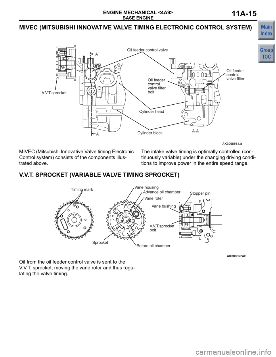
MIVEC (MITSUBISHI INNOVATIVE VALVE TIMING ELECTRONIC CONTROL SYSTEM)
AK300856AD
A
A
A-A
Oil feeder control valve
Oil feeder
control
valve filter
Oil feeder
control
valve filter
bolt
Cylinder head
Cylinder block
V.V.T.sprocket
M I VEC (Mit su bis h i Inn o va tive V a lve tim i ng Elect r o n ic
Con
t rol system) consist s of th e compon ent s illus
-
trated above .
The int a ke valve timing is optimally controlled (con-
tinuously variable) un der the chan ging driving condi-
tions to improv e po we r in th e entire sp eed ra nge.
V. V . T . SPROCKET (V ARIABLE V A L V E TIMING SPROCKET)
AK300857
Vane bushing
AB
SprocketVane roter
V.V.T.sprocket
bolt
Timing mark
Vane housing
Advance oil chamber
Retard oil chamber
Stopper pin
Oil from the oil fe
eder control valve is sent t o the
V
. V . T . sp rocket, moving the vane roto r and thus reg u
-
lating the valve timing.
Page 69 of 364
BASE ENGINE
ENGINE MECHANICAL <4A9>11A-21
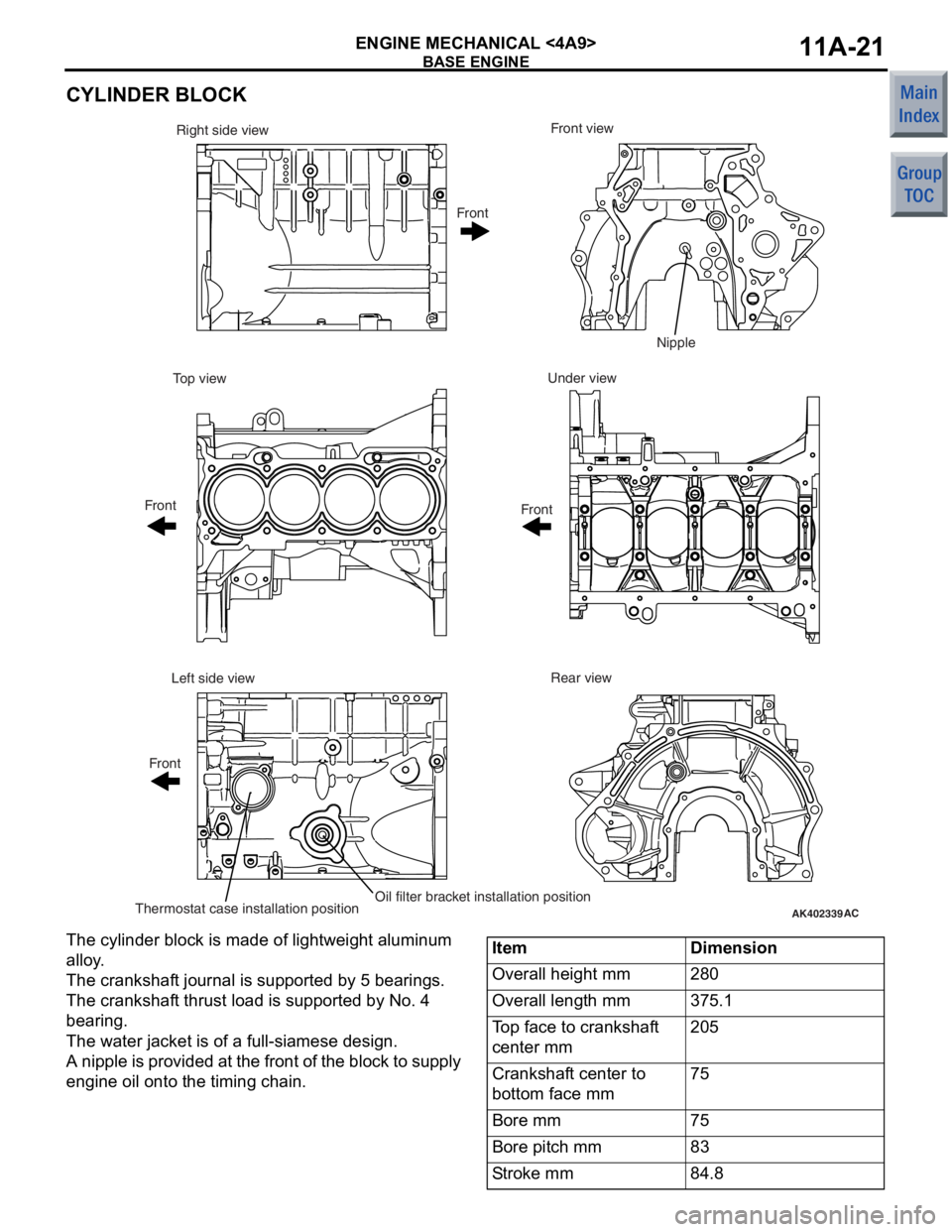
CYLINDER BLOCK
AK402339AC
Front view
Right side view
Under view
Top view
Rear view
Left side view
Thermostat case installation positionOil filter bracket installation position Front
Front Front Front
Nipple
The cylinder b
l ock is ma de of ligh twe i ght aluminum
allo
y .
The crankshaf t jo urnal is supp orted b y 5 b earing s .
The crankshaf
t thru st load is supporte d by No . 4
bearin
g.
The water jacket is of a full-siamese de sig n .
A nipple is p r ovid ed at the fr o n t of the block to su pply
engin
e oil onto the timin g ch ain.
ItemDimension
Overall height mm280
Overall length mm375.1
Top face to crankshaft
center mm205
Crankshaft center to
bottom face mm75
Bore mm75
Bore pitch mm83
Stroke mm84.8
Page 79 of 364
BASE ENGINE
ENGINE MECHANICAL <4A9>11A-31
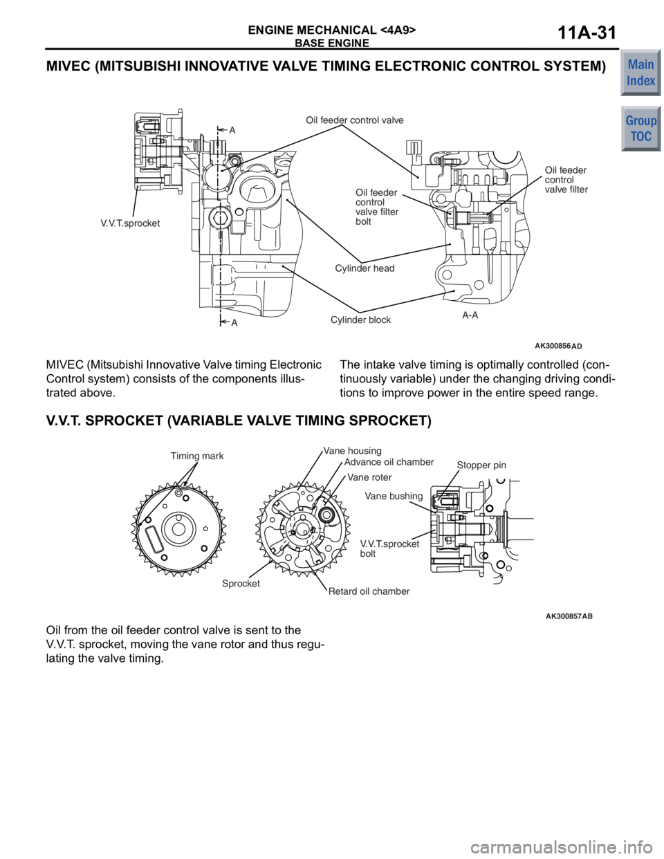
MIVEC (MITSUBISHI INNOVATIVE VALVE TIMING ELECTRONIC CONTROL SYSTEM)
AK300856AD
A
A
A-A
Oil feeder control valve
Oil feeder
control
valve filter
Oil feeder
control
valve filter
bolt
Cylinder head
Cylinder block
V.V.T.sprocket
M I VEC (Mit su bis h i Inn o va tive V a lve tim i ng Elect r o n ic
Con
t rol system) consist s of th e compon ent s illus
-
trated above .
The int a ke valve timing is optimally controlled (con-
tinuously variable) un der the chan ging driving condi-
tions to improv e po we r in th e entire sp eed ra nge.
V. V . T . SPROCKET (V ARIABLE V A L V E TIMING SPROCKET)
AK300857
Vane bushing
AB
SprocketVane roter
V.V.T.sprocket
bolt
Timing mark
Vane housing
Advance oil chamber
Retard oil chamber
Stopper pin
Oil from the oil fe
eder control valve is sent t o the
V
. V . T . sp rocket, moving the vane roto r and thus reg u
-
lating the valve timing.
Page 88 of 364
GROUP 12
ENGINE
LUBRICATION
CONTENTS
GENERAL INFORMATIO N . . . . . . . .12-2
OIL PUMP<4A9> . . . . . . . . . . . . . . . .12-4
RELIEF VALVE<4A9> . . . . . . . . . . . .12-4
OIL SCREEN<4A9> . . . . . . . . . . . . . .12-5
OIL FILTER<4A9> . . . . . . . . . . . . . . .12-5
OIL PAN<4A9> . . . . . . . . . . . . . . . . . .12-6
OIL LEVEL GAUGE, OIL FILLER CAP,
OIL DRAIN PLUG<4A9> . . . . . . . . . .12-6
OIL COOLER<4G1> . . . . . . . . . . . . . .12-7
Page 89 of 364
GENERAL INFORMATION
ENGINE LUBRICATION12-2
GENERAL INFORMATION
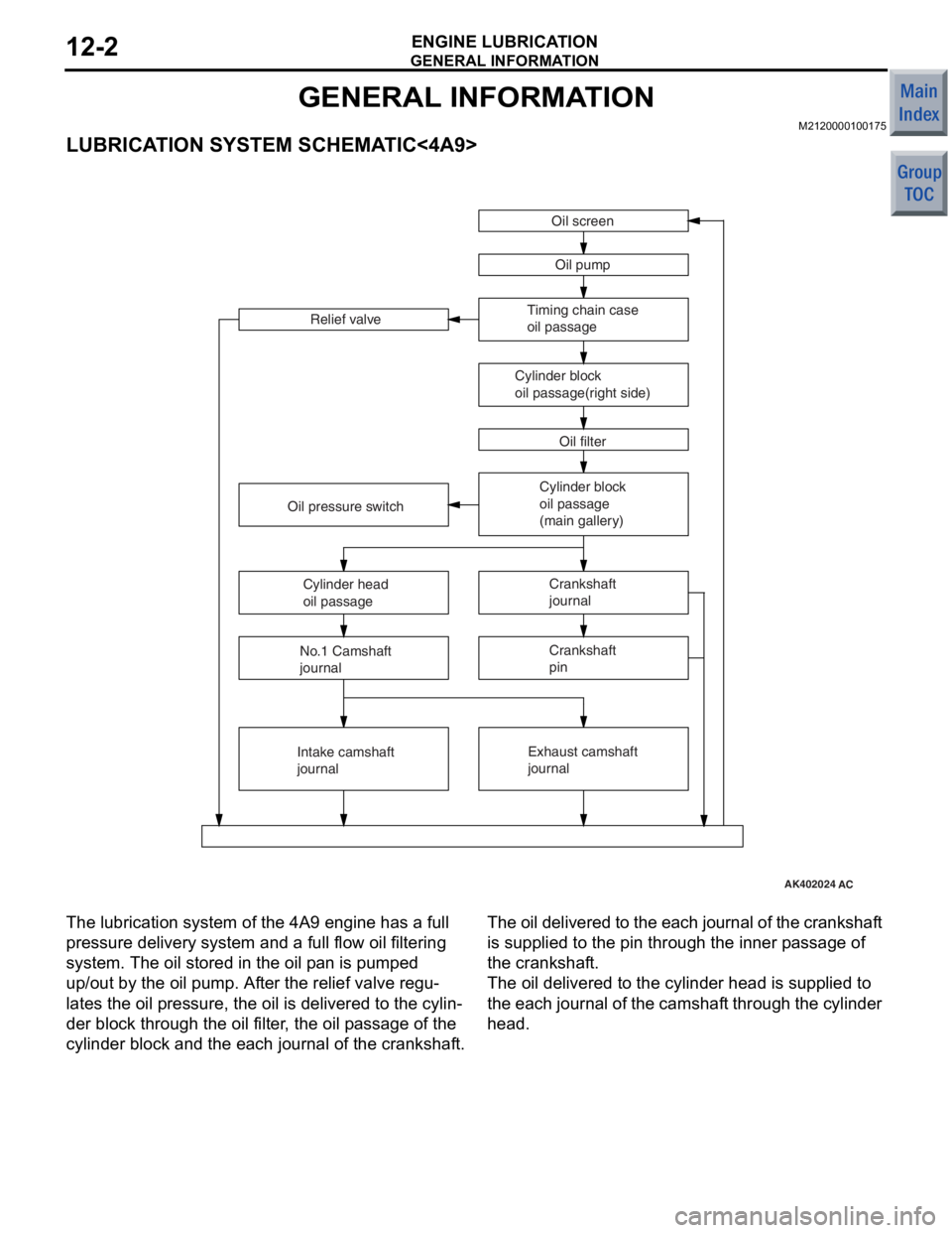
M2120000100175
LUBRICATION SYSTEM SCHEMATIC<4A9>
AK402024AC
Oil screenOil pump
Timing chain case
oil passage
Cylinder block
oil passage(right side) Oil filter
Relief valve
Cylinder block
oil passage
(main gallery)Crankshaft
journal
Exhaust camshaft
journal
Oil pressure switch
Cylinder head
oil passage
No.1 Camshaft
journal
Intake camshaft
journal Crankshaft
pin
The lu
brication system of th e 4A9 en gine has a full
pressure de
livery system and a full flow oil filtering
system. The o
il stored in the oil p an is pumped
up/out
by th e oil pump. Af ter the relie f valve regu
-
lates the oil p r essure, th e oil is delivere d to th e cylin-
der block through the o il f ilte r , the o il p a ssag e of the
cylinde
r blo ck a nd the each jou r nal o f the crankshaf t.
The oil del ivered to the ea ch jo urnal of th e cranksh af t
is supplied
to the pin th rough the in ner p a ssage of
the crankshaf
t.
The oil delivered to the cylinder head is supplied t o
the ea
ch journa l of the camshaf t th rough the cylinde r
head.
Page 90 of 364
GENERAL INFORMATION
ENGINE LUBRICATION12-3
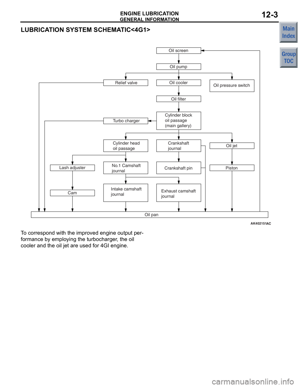
LUBRICATION SYSTEM SCHEMATIC<4G1>
AK402151AC
Oil screen
Oil pump
Oil filter
Relief valve
Cylinder block
oil passage
(main gallery)Crankshaft
journal
Exhaust camshaft
journal
Oil pan Oil pressure switch
Cylinder head
oil passage
No.1 Camshaft
journal
Intake camshaft
journal Crankshaft pin
PistonOil jet
Oil cooler
Turbo charger
Lash adjuster Cam
To correspond with the impr oved engine outp u t per-
formance b y emplo y ing the tu rboch a rger , the oil
cooler and
the oil jet are u s ed for 4GI engine.
Page 92 of 364
OIL SCREEN<4A9>
ENGINE LUBRICATION12-5
OIL SCREEN<4A9>
M2120004000039
AK305372AB
Timing chain case
Oil pan
Oil screen
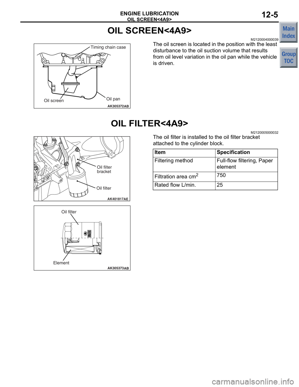
The oil screen is located in the po sition with the lea s t
disturbance to
the oil suction vo lume that result s
from oil
level variat ion in the oil p an while the vehicle
is d
r ive n .
OIL FIL T ER<4A9>
M21200050 0003 2
AK401817AE
Oil filterOil filter
bracket
AK305373
AB
Element
Oil filter
The oil filter is inst alled to the oil filter b r acket
att
a che d to the cylin der block.
ItemSpecification
Filtering methodFull-flow filtering, Paper
element
Filtration area cm2750
Rated flow L/min.25
Page 94 of 364
OIL COOLER<4G1>
ENGINE LUBRICATION12-7
OIL COOLER<4G1>
M2120008000020
AK402142
Oil outletOil inlet
To cylinder block
From oil filter
Coolant inlet
(from throttle body)
Coolant outlet
(to water inlet pipe)
Oil cooler boltOil cooler
AC
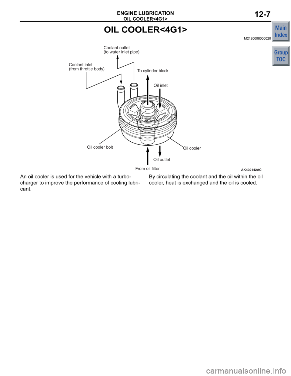
An
oil cooler is used for the vehicle wit h a turb o-
charge r to improve the per formance of cooling lubri-
cant.
By circulating the coolant an d the o il within t he oil
cooler
, he at is exchang ed an d the o il is coole d .
Page 213 of 364
TECHNICAL FEATURES
GENERAL00-28
ENVIRONMENTAL PROTECTION
M2000027000279
Mitsubishi has given careful consideration to protec-
tion of natural resources and the environment in the
vehicle. Environmentally friendly features are shown
below.
IMPROVEMENT ON RECYCLING EFFICIENCY
ClassificationMain Components
Components made
of recycled
materialsChip materials produced during manufacturing process has been reused as the
following components: Door inside handle, bu mper, radiator grille, instrument panel,
door trims, or floor padding.
Waste materials produced by other i ndustries have been reused as the following
components: Engine oil level gauge, air filter casing, and sound absorbing materials
for dash panel
Components made
of materials which
can be easily
recycledThermoplastic resin has been utilised as the following components: Inside door
handle, bumper, radiator grille, instrument panel, door trim
Thermoplastic resin has been utilised as t he following components: Vacuum hose for
engine control, air intake hose, hood weather strip, tailgate opening weather strip
REDUCTION OF MATERIAL BURDEN ON ENVIRONMENT
ItemMain Components
Elimination of
environmental
burden materialsLead-free materials have been utilised as the following components: Radiator, fuel
tank, power steering oil pressure hose, el ectrodeposition paint for body, glass ceramic
print, heater core, battery terminals, wiring harness
Non-asbestos material has been used for engine gaskets.
PVC(polyvinyl chloride)-free materials ha ve been used for the waterproofing film.
Prevention of
ozone depletionAir conditioner filled with new refrigerant (HFC 134a) has been installed.
Prevention of air
pollutionEmployment of a metal cylinder head gasket reduces the volume of incomplete
combustion generated between the cylinder block and cylinder head, and suppresses
the level of unburned hydrocarbon (HC).
SERVICEABILITY AND RELIABILITY
M2000028000528
MULTI USE TESTER-III (M.U.T.-III) SUB
ASSEMBLY
Comprehensive improvements have been made to
the M.U.T.-II, a tester for diagnosing problems with
the electronic control system. For easier servicing,
the newly developed M.U.T.-III has greatly improved
functions and is much easier to use. The M.U.T.-III
expands the functions of the M.U.T.-II in the following
ways:
1.CAN* bus diagnosis
•Auto diagnosis function for the CAN commu-
nications bus line is added.
NOTE: *CAN: Controller Area Network (for further
details, refer to GROUP 54C
P.54C-2).