wiring MITSUBISHI COLT 2006 Service Repair Manual
[x] Cancel search | Manufacturer: MITSUBISHI, Model Year: 2006, Model line: COLT, Model: MITSUBISHI COLT 2006Pages: 364, PDF Size: 11.65 MB
Page 2 of 364

GENERAL INFORMATION
ANTI-SKID BRAKE SYSTEM (ABS)35B-2
GENERAL INFORMATION
M2351000100409
FEATURES
The ABS ensures directional stability and controlla-
bility during hard braking.
For vehicles with this type of ABS, 4 sensors (4
channels) are installed on front and rear wheels
allowing independent left and right control.
The system has the following features:
•EBD (Electronic Brake-force Distribution system)
control has been added to provide the ideal brak
-
ing force for the rear wheels.
•Magnetic encoder for wheel speed detection has
been installed as a sensing device instead of the
rotor.
•For wiring harness saving and secure data com-
munication, CAN* bus has been adopted as a
tool of communication with another ECU.
NOTE: *: For more information about CAN (Control-
ler Area Network), refer to Group 54C, General Infor-
mation P.54C-2.
EBD CONTROL
In ABS, electronic control is used so the rear wheel
brake hydraulic pressure during braking is regulated
by rear wheel control solenoid valves in accordance
with the vehicle's rate of deceleration, and the front
and rear wheel slippage which are calculated from
the signals received from the various wheel speed
sensors. EBD control provides a high level of control
for both vehicle braking force and vehicle stability.
The system has the following features:
•Because the system provides the optimum rear
wheel braking force regardless of vehicle load
condition and the condition of the road surface,
the system reduces the required pedal depres
-
sion force, particularly when the vehicle is heavily
loaded or driven on road surfaces with high fric
-
tional coefficients.
•Because the duty placed on the front brakes is
reduced, the increase in pad temperature can be
controlled during brakes application to improve
the wear resistance characteristics of the pad.
•Control valves such as the proportioning valve
are not required.
SPECIFICATIONS
ItemSpecification
ABS control method4-sensor, 4-channel
Wheel speed
sensorMagnetic encoderFront86 (N pole:43 S pole:43)
Rear86 (N pole:43 S pole:43)
Ty p eSemiconductor
Page 6 of 364

CONSTRUCTION DESCRIPTION
ANTI-SKID BRAKE SYSTEM (ABS)35B-6
CONSTRUCTION DESCRIPTION
SENSORSM2351001000427
WHEEL SPEED SENSORS AND MAG-
NETIC ENCODER FOR WHEEL SPEED
DETECTION
AC601358
Rear wheel speed sensor
Front wheel speed sensor
Front Rear
Encoder for wheel
speed detection Encoder for wheel
speed detectionRear wheel speed sensor
Encoder for wheel
speed detection
AB
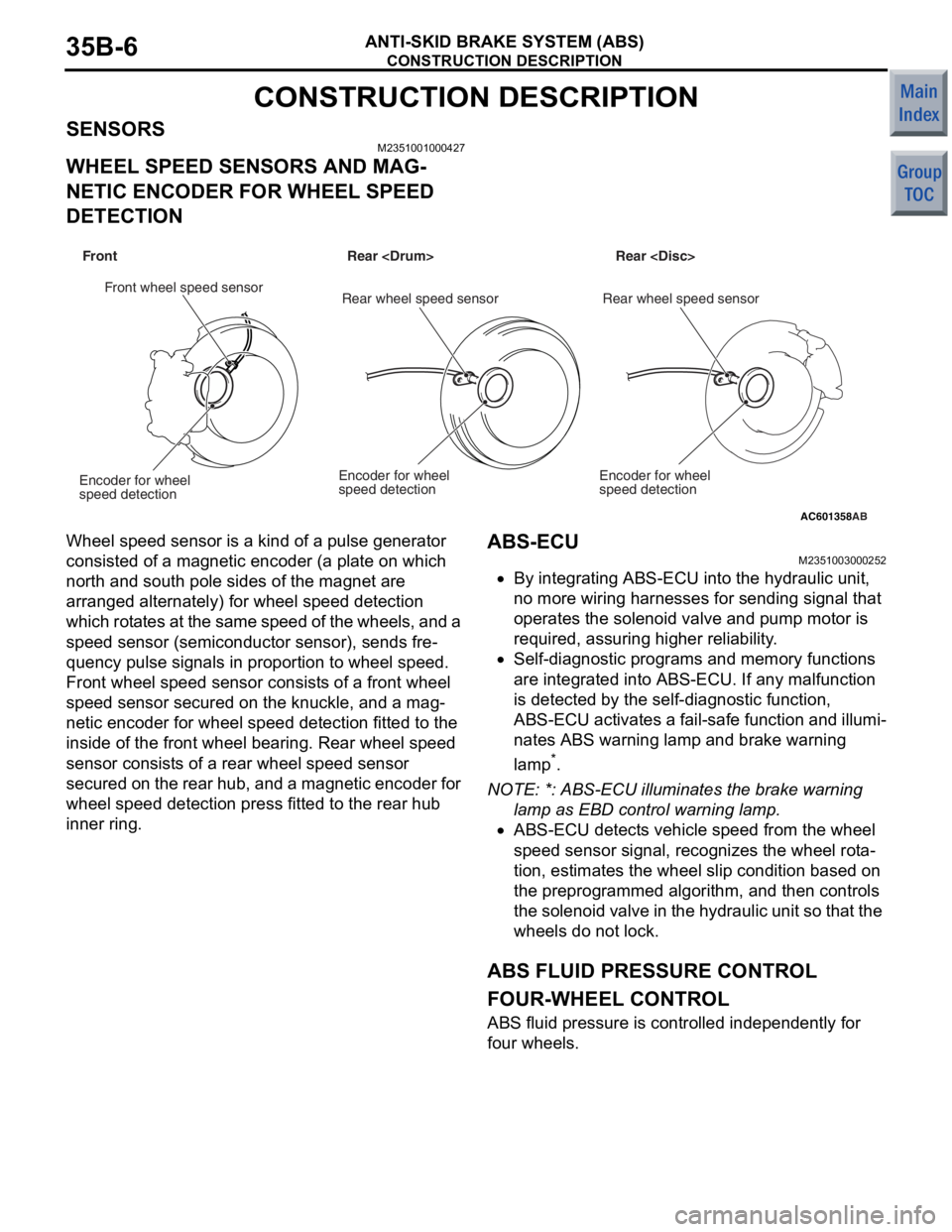
Wheel spee d se nsor is a kin d of a pulse gen erator
consisted of
a mag netic encoder (a pla t e on which
north an
d so uth po le sides of th e mag net are
arrange
d alte rnately) for wh eel speed detection
which rot
a tes at the same speed of the wheels, and a
spee
d sen s or (semicon duct o r se nsor), send s fre
-
quency pulse sig nals in proportion to wh eel spee d.
Front wheel sp eed sensor co nsist s of a front whe e l
spee
d sen s or secu red on the knuckle, and a mag
-
netic encoder for wheel spee d dete c tio n fitt ed to th e
inside o
f the fro n t wheel bearing. Rear wh eel speed
sensor consist
s o f a rear wh eel speed sensor
secured on
the re ar hub, and a magn etic encoder fo r
whe
e l speed detection press fit t ed to the rear hub
inner ring.
ABS-ECU
M23510030 0025 2
•By integrating ABS-ECU into the hydraulic unit ,
no
more wiring h a rnesses for sending signal that
ope
rates the solen o id valve an d pump mo tor is
requ
ired, assuring high er reliability .
•Self-diag nostic p r ograms an d memory functions
are
integrated into ABS-ECU. If any malfunction
is dete
c ted by th e se lf-diagnostic function,
ABS-ECU activates
a fail-s afe function and illumi
-
nates ABS warning lamp and brake warning
la
mp
*.
NO TE: *: ABS-E CU illuminates the brake warning
l
a
m
p as EBD c o nt ro l wa rn in g la m p .
•ABS-ECU detects vehicle speed from the wheel
speed sensor signal, reco
gnizes the whee l rot a
-
tion, estimates the wheel slip condition based on
the
preprog rammed algorithm, a nd the n co ntrols
th
e soleno id valve in the hydr aulic u n it so th at the
wheels d
o not lock.
ABS FLUID PRESSURE CONTROL
FOUR-WHEEL CONTROL
ABS fluid pressure is controlled indep enden tly for
four whee
ls.
Page 7 of 364

CONSTRUCTION DESCRIPTION
ANTI-SKID BRAKE SYSTEM (ABS)35B-7
EBD FLUID PRESSURE CONTROL
AC208548AB
Ideal distribution curve when
seated by fixed personsEBD operating conceptual design
Rear braking force
Ideal distribution curve when seated by one persons Braking force distribution curve
by the existing proportioning valveBraking force distribution
by EBD control
Front braking force
Braking Force
Improved
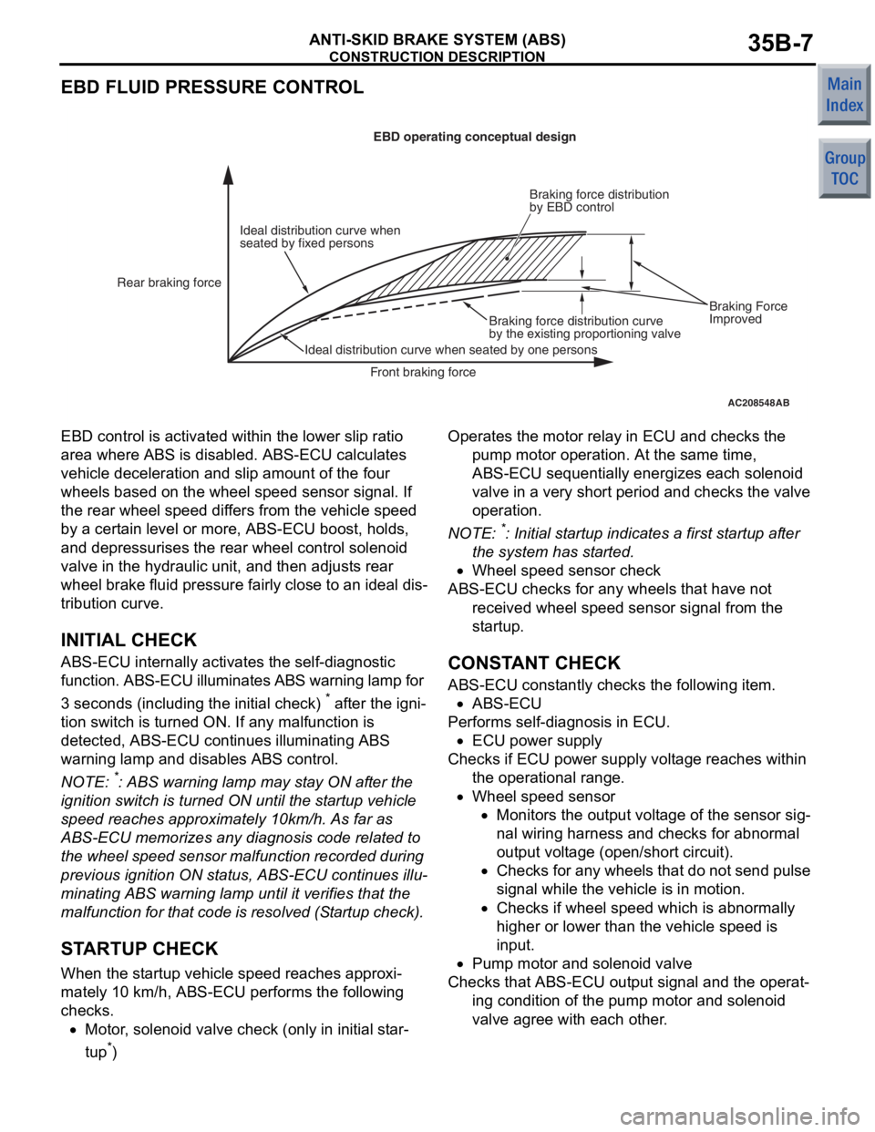
EBD control is
activate d within the lower slip ratio
area where
ABS is disab l ed. ABS-ECU calculates
vehicle
decelera t ion a nd slip amou nt of th e four
whe
e ls based on the wheel sp eed senso r signal. If
the rear
wh eel speed dif f ers f r om th e ve hicle speed
by a
cert ain level or more, ABS-ECU boost, holds,
and de
pressurises the rea r wh eel contro l so leno id
valve in the h
y drau lic unit, and then a d just s rear
whe
e l b r ake fluid pressure fa ir ly close to an ideal dis
-
tribution curve.
INITIAL CHECK
ABS-ECU inter nally activates the self-d iagno stic
function. ABS-ECU illuminates
ABS warning l a mp for
3 seconds (in
c lu ding the in itia l check)
* after th e ign i-
tion switch is turned ON. If a n y malf unction is
detected, ABS-ECU cont
inues illuminating ABS
war
n ing lamp and disables ABS cont rol.
NOTE: *: ABS warning lamp may st ay ON af ter the
ignition
switch is turned ON un til t he st artu p ve hicle
spee
d reaches approximately 10km/h . As far as
ABS-ECU memorizes any d i agn osis code related t o
the
whee l speed sen s or malfunct i on record ed d u ring
previous ignition ON st atus, ABS-ECU continues illu
-
mina ting ABS warn ing lamp until it verif i es that th e
malfunct
i on for tha t co de is resolved (S t a rtup che ck).
STARTUP CHECK
When th e st artup veh i cle sp eed re ache s app roxi-
mately 10 km/h, ABS-ECU performs the following
checks.
•Motor, solen o id valve check (onl y i n ini t ial st ar-
tup*)
Operat es the motor relay in ECU and checks the
pump motor op eratio n. At the same time,
ABS-ECU sequentially e nergizes each solenoid
valve in a ve ry sh ort perio d and ch ecks the valve
ope ration .
NOTE: *: Initia l st artu p ind i ca tes a first st artup af ter
the
system has st arted .
•Whee l speed sensor check
ABS-ECU che cks for a n y whee ls that ha ve no t
received whee l sp eed sens or signal from the
st artu p.
CONSTANT CHECK
ABS-ECU con s t antly ch ecks th e following item.
•ABS-ECU
Performs se lf-diagnosis in ECU.
•ECU power supply
Checks if ECU po we r sup p ly volt ag e reaches within
the operat ional range .
•Whee l speed sensor
•Monitors the ou tput volt age of the sensor sig-
nal wiring ha rness an d che c ks for a bnormal
output
volt ag e (ope n/sho r t circuit).
•Checks fo r any wheels tha t do n o t send pu lse
sig
nal while th e ve hicle is in motion.
•Checks if wheel spee d which is abno rmally
high
er or lo we r than the vehicle speed is
inpu
t.
•Pump mo tor and solenoid valve
Checks tha t ABS-ECU outp u t signal and t he ope rat-
ing co ndition of the pump motor an d so leno id
valve agree
with ea ch ot her .
Page 26 of 364

GENERAL INFORMATION
HEATER, AIR CONDITIONER AND VENTILATION55-2
GENERAL INFORMATION
M2551000100759
For the heater and A/C system, the heater, the
blower and the cooling unit are integrated as one unit
to reduce weight and size. For A/C system, the man
-
ual A/C has been adopted.
FEATURES
IMPROVEMENTS IN COMFORT
•Adoption of low noise, large air volume heater
and A/C system
•Adoption of smaller air intake box for larger pas-
senger leg space.
•Optimising the areas of the outside air induction
hole and the air outlet improves ventilation per
-
formance as well as the quietness of the room
•Adoption of clean air filter with deodorant function
for cleaner air in the compartment.
IMPROVEMENTS IN OPERATION
PERFORMANCE
•Inside/outside air selection switch has been
changed to a pushbutton switch.
•Improved operation ability by the enlarged tab on
the dial knob
•Air amount and temperature only are controlled
automatically for easier operation.
RELIABLE VISUAL FIELD
(IMPROVEMENT IN SAFETY)
•Current type defroster nozzle has been adopted
to improve defogging performance (Shortens
windshield fogging time).
•Defroster vents have been integrated to secure
better defogging pattern.
•Black coin drop prevention ribs are used on the
defroster to prevent its reflection on the wind
-
shield, providing sufficient field of vision for safety
IMPROVEMENTS IN FUEL ECONOMY
•Wider condenser area reduces load to the A/C
and improves fuel consumption.
•Energy conservation control using outside air
temperature sensor is adopted for vehicles with
manual A/C as well.
•A small-size, highly-efficient compressor has
been adopted.
•Simpler wiring and weight reduction are achieved
by installation of CAN communication system
GLOBAL ENVIRONMENT PROTECTION
Adoption of HFC134a for refrigerant.
IMPROVEMENTS IN SERVICE QUALITY
•Reduction of refrigerant gas leakage and
improvement in serviceability by incorporating
condenser and receiver
•The layout of refrigerant line for better workability
is adopted.
RESPONSIBILITY IMPROVEMENT
Reliable information transmission is achieved by
connecting A/C-ECU and each ECU via CAN com
-
munication.
Page 134 of 364

GROUP 54
CHASSIS
ELECTRICAL
CONTENTS
CHASSIS ELECTRICAL . . . . . . . . . . . . . . . . . . . . . . . . . . . . . . .54A
SMART WIRING SYSTEM (SWS) . . . . . . . . . . . . . . . . . . . . . . .54B
CONTROLLER AREA NETWORK (CAN) . . . . . . . . . . . . . . . . .54C
Page 139 of 364

GENERAL INFORMATION
CONTROLLER AREA NETWORK (CAN)54C-2
GENERAL INFORMATION
M2542000100159
CAN, an abbreviation for Controller Area Network, is
an ISO-certified international standard for a serial
multiplex communication protocol
*1. A communica-
tion circuit employing the CAN protocol connects
each ECU, and sensor data can be shared among,
which enables more reduction in wiring.
NOTE: *1: The regulations have been decided in
detail, from software matters such as the necessary
transmission rate for communication, the system,
data format, and communication timing control
method to hardware matters such as the harness
type and length and the resistance values.
CAN offers the following advantages.
•Transmission rates are much faster than those in
conventional communication (up to 1 Mbps),
allowing much more data to be sent.
•It is exceptionally immune to noise, and the data
obtained from each error detection device is more
reliable.
•Each ECU connected via the CAN communicates
independently, therefore if the ECU enters dam
-
aged mode, communications can be continued in
some cases.
Page 173 of 364

GENERAL INFORMATION
CHASSIS ELECTRICAL54A-2
GENERAL INFORMATION
M2540000100302
FEATURES
IMPROVEMENT OF VISUAL OBSERVA-
TION AND SAFETY, AND ENHANCEMENT
OF USER-FRIENDLINESS AND VERSA
-
TILITY
•The large four headlamps with the lightweight
resin lenses have been adopted.
•The high-mounted stop lamp has been installed
on the tailgate for all models.
•Combination meters and ECUs are connected
using CAN to ensure the transmission of informa
-
tion.
•The combination meters are provided integrated
with a perfect round-shaped speedometer where
the needles operate at the wider angle.
IMPROVEMENTS IN SERVICE QUALITY
•Diagnosis connector for inspection with M.U.T.-III
is installed.
•Diagnosis and service data are integrated in the
combination meter, enabling communication with
M.U.T.-III
BETTER PRODUCT PACKAGE
•The smart wiring system (SWS) has been
adopted for the lamp control including the head
-
lamp auto turn-off and fog lamp unattended-oper-
ation reminder.
Page 204 of 364

TECHNICAL FEATURES
GENERAL00-19
ACTIVE SAFETY
M2000031000528
ANTI-SKID BRAKE SYSTEM (ABS)
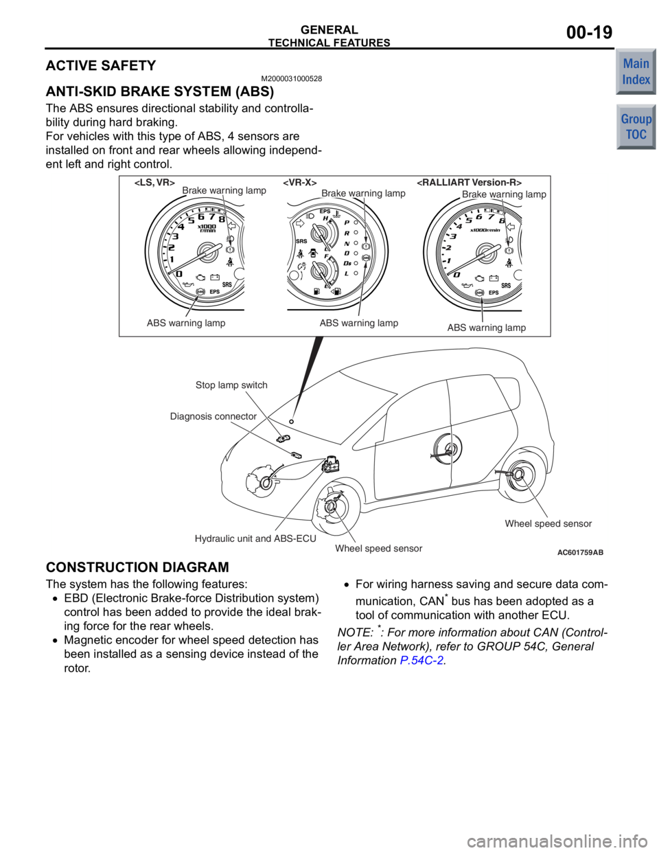
The ABS ensures directional stability and controlla-
bility during hard braking.
For vehicles with this type of ABS, 4 sensors are
installed on front and rear wheels allowing independ
-
ent left and right control.
AC601759AB
ABS warning lamp
Brake warning lamp
ABS warning lamp
Brake warning lampBrake warning lamp
ABS warning lamp
Stop lamp switch
Hydraulic unit and ABS-ECUWheel speed sensor Wheel speed sensor
Diagnosis connector
CONSTRUCTION DIAGRAM
The syst
em has the following features:
•EBD (Electronic Bra ke-fo rce Distributio n system)
co ntrol has been added to provide t he ideal brak
-
in g force for th e rear wheels.
•Magnetic en coder for whee l speed de tection ha s
bee n inst alled as a se nsing device instead of the
rotor .
•For wiring h arness saving an d secure data com-
municatio n, CAN* b us h as be en ad opted a s a
too l of communication with another ECU.
NO TE: *: Fo r more information abo ut CAN (Control-
ler Area Netwo rk), re fer to GROUP 54C, Genera l
Information
P.54C-2.
Page 207 of 364

TECHNICAL FEATURES
GENERAL00-22
ACTIVE STABILITY CONTROL SYSYEM
(ASC)
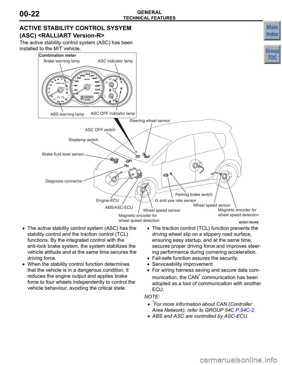
The active stability control system (ASC) has been
installed to the M/T vehicle.
AC601760AB
ABS warning lamp
Diagnosis connector Stoplamp switch
Steering wheel sensor
Wheel speed sensor Wheel speed sensor
G and yaw rate sensorParking brake switch
ASC OFF switch ASC indicator lamp
ASC OFF indicator lamp
Brake warning lamp
Combination meter
Brake fluid level sensor ABS/ASC-ECU
Engine-ECU
Magnetic encoder for
wheel speed detection Magnetic encoder for
wheel speed detection
•The
active st ability control syst em (ASC) has the
st ab ility control and t he traction control (TCL)
fun ctio ns. By the integra ted control with th e
ant i-lock b rake system, the system stabilizes th e
ve hicle attitu de and at the same time secures the
drivin g force.
•When the st ability control fun ction dete rmin es
tha t the vehicle is in a dangerou s condition, it
redu ces the e ngine outpu t and a pplies b rake
force to f our wheels indepe ndently to control th e
ve hicle be haviour, avoiding the critical state.
•The tract ion control (TCL) fun ction prevent s the
drivin g wheel slip on a slippery road sur face,
ensurin g easy st artup, an d at the same time,
secure s proper drivin g force and improves ste er
-
in g perfo rmance du ring cornering acce leration.
•Fail-safe functio n assures the security.
•Serviceability imp rovement
•For wiring h arness saving an d secure data com-
municatio n, the CAN* co mmunicatio n has been
ado pted a s a t ool o f commun ication with ano ther
ECU.
NO TE: .
•*For more informatio n about CAN (Con troller
Area Net wor k), refe r to GROUP 54C
P.54C-2.
•ABS and ASC are controlled by ASC-ECU.
Page 213 of 364

TECHNICAL FEATURES
GENERAL00-28
ENVIRONMENTAL PROTECTION
M2000027000279
Mitsubishi has given careful consideration to protec-
tion of natural resources and the environment in the
vehicle. Environmentally friendly features are shown
below.
IMPROVEMENT ON RECYCLING EFFICIENCY
ClassificationMain Components
Components made
of recycled
materialsChip materials produced during manufacturing process has been reused as the
following components: Door inside handle, bu mper, radiator grille, instrument panel,
door trims, or floor padding.
Waste materials produced by other i ndustries have been reused as the following
components: Engine oil level gauge, air filter casing, and sound absorbing materials
for dash panel
Components made
of materials which
can be easily
recycledThermoplastic resin has been utilised as the following components: Inside door
handle, bumper, radiator grille, instrument panel, door trim
Thermoplastic resin has been utilised as t he following components: Vacuum hose for
engine control, air intake hose, hood weather strip, tailgate opening weather strip
REDUCTION OF MATERIAL BURDEN ON ENVIRONMENT
ItemMain Components
Elimination of
environmental
burden materialsLead-free materials have been utilised as the following components: Radiator, fuel
tank, power steering oil pressure hose, el ectrodeposition paint for body, glass ceramic
print, heater core, battery terminals, wiring harness
Non-asbestos material has been used for engine gaskets.
PVC(polyvinyl chloride)-free materials ha ve been used for the waterproofing film.
Prevention of
ozone depletionAir conditioner filled with new refrigerant (HFC 134a) has been installed.
Prevention of air
pollutionEmployment of a metal cylinder head gasket reduces the volume of incomplete
combustion generated between the cylinder block and cylinder head, and suppresses
the level of unburned hydrocarbon (HC).
SERVICEABILITY AND RELIABILITY
M2000028000528
MULTI USE TESTER-III (M.U.T.-III) SUB
ASSEMBLY
Comprehensive improvements have been made to
the M.U.T.-II, a tester for diagnosing problems with
the electronic control system. For easier servicing,
the newly developed M.U.T.-III has greatly improved
functions and is much easier to use. The M.U.T.-III
expands the functions of the M.U.T.-II in the following
ways:
1.CAN* bus diagnosis
•Auto diagnosis function for the CAN commu-
nications bus line is added.
NOTE: *CAN: Controller Area Network (for further
details, refer to GROUP 54C
P.54C-2).