display MITSUBISHI COLT 2008 Owner's Manual (in English)
[x] Cancel search | Manufacturer: MITSUBISHI, Model Year: 2008, Model line: COLT, Model: MITSUBISHI COLT 2008Pages: 450, PDF Size: 14.57 MB
Page 6 of 450
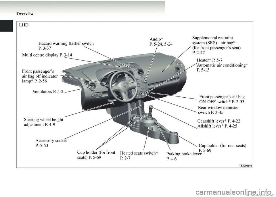
Overview
Supplemental restraint
system (SRS) - air bag*
(for front passenger’s seat)
P. 2 - 4 7
Accessory socket
P. 5-60
Ventilators P. 5-2
Hazard warning flasher switch
P. 3 - 3 7
Cup holder (for rear seats)
P. 5-69
Parking brake lever
P. 4-6 Gearshift lever* P. 4-22
Allshift lever* P. 4-25
Steering wheel height
adjustment P. 4-9
Heated seats switch*
P. 2-7Front passenger’s air bag
ON-OFF switch* P. 2-53
Audio*
P. 5-24, 5-24
Heater* P. 5-7
Automatic air conditioning*
P. 5 - 1 3
Multi centre display P. 3-14
LHD
Rear window demister
switch P. 3-45
Cup holder (for front
seats) P. 5-69
Front passenger’s
air bag off indicator
lamp* P. 2-56
Page 7 of 450
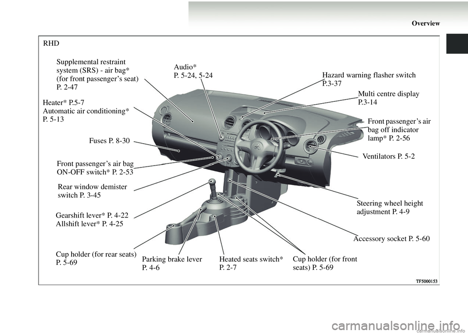
Overview
Fuses P. 8-30
RHD
Supplemental restraint
system (SRS) - air bag*
(for front passenger’s seat)
P. 2-47
Accessory socket P. 5-60Ventilators P. 5-2
Hazard warning flasher switch
P. 3 - 3 7
Cup holder (for rear seats)
P. 5 - 6 9 Parking brake lever
P. 4-6
Gearshift lever* P. 4-22
Allshift lever* P. 4-25
Steering wheel height
adjustment P. 4-9
Heated seats switch*
P. 2-7
Rear window demister
switch P. 3-45 Audio*
P. 5-24, 5-24
Heater* P.5-7
Automatic air conditioning*
P. 5-13 Multi centre display
P. 3 - 1 4
Front passenger’s air bag
ON-OFF switch* P. 2-53 Front passenger’s air
bag off indicator
lamp* P. 2-56
Cup holder (for front
seats) P. 5-69
Page 121 of 450
3
Instruments and controls
Instruments. . . . . . . . . . . . . . . . . . . . . . . . . . . . . . .3- 2
Indicator and warning lamps . . . . . . . . . . . . . . . . .3- 7
Indicator lamps. . . . . . . . . . . . . . . . . . . . . . . . . . . .3- 8
Warning lamps . . . . . . . . . . . . . . . . . . . . . . . . . . . .3- 9
Multi-centre display . . . . . . . . . . . . . . . . . . . . . . . .3- 14
Combination headlamps and dipper switch . . . . . .3- 31
Headlamp levelling switch. . . . . . . . . . . . . . . . . . .3- 34
Turn-signal lever . . . . . . . . . . . . . . . . . . . . . . . . . .3- 36
Hazard warning flasher switch. . . . . . . . . . . . . . . .3- 37
Front fog lamp switch* . . . . . . . . . . . . . . . . . . . . .3- 37
Rear fog lamp switch . . . . . . . . . . . . . . . . . . . . . . .3- 38
Wiper and washer switch . . . . . . . . . . . . . . . . . . . .3- 39
Rear window demister switch . . . . . . . . . . . . . . . .3- 45
Horn switch . . . . . . . . . . . . . . . . . . . . . . . . . . . . . .3- 46
Page 125 of 450
Instruments and controls3-5
3
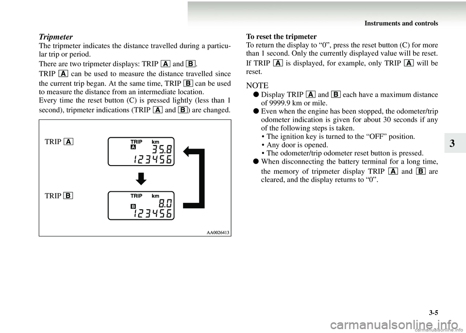
Tripmeter
The tripmeter indicates the dist ance travelled during a particu-
lar trip or period.
There are two tripmeter displays: TRIP and .
TRIP can be used to measur e the distance travelled since
the current trip began. At the same time, TRIP can be used
to measure the distance from an intermediate location.
Every time the reset button (C) is pressed lightly (less than 1
second), tripmeter indications (TRIP and ) are changed. To reset the tripmeter
To return the display to “0”, press the reset button (C) for more
than 1 second. Only the currently displayed value will be reset.
If TRIP is displayed, for example, only TRIP will be
reset.
NOTE
●
Display TRIP and each have a maximum distance
of 9999.9 km or mile.
● Even when the engine has been stopped, the odometer/trip
odometer indication is given for about 30 seconds if any
of the following steps is taken.
• The ignition key is turned to the “OFF” position.
• Any door is opened.
• The odometer/trip odometer reset button is pressed.
● When disconnecting the batter y terminal for a long time,
the memory of tripmeter display TRIP and are
cleared, and the display returns to “0”.
TRIP
TRIP
Page 127 of 450
Instruments and controls3-7
3
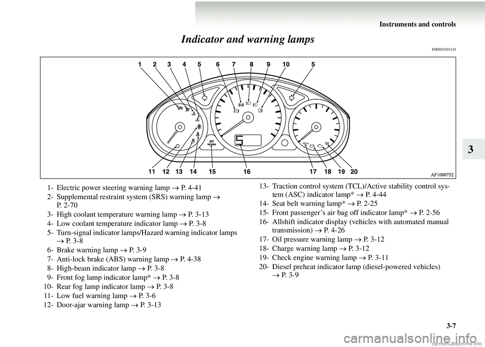
Indicator and warning lamps
E00501501324
1- Electric power steering warning lamp
→ P. 4-41
2- Supplemental restraint system (SRS) warning lamp →
P. 2 - 7 0
3- High coolant temperature warning lamp → P. 3-13
4- Low coolant temperature indicator lamp → P. 3-8
5- Turn-signal indicator lamps/Hazard warning indicator lamps → P. 3-8
6- Brake warning lamp → P. 3-9
7- Anti-lock brake (ABS) warning lamp → P. 4-38
8- High-beam indicator lamp → P. 3-8
9- Front fog lamp indicator lamp* → P. 3-8
10- Rear fog lamp indicator lamp → P. 3-8
11- Low fuel warning lamp → P. 3-6
12- Door-ajar warning lamp → P. 3-13 13- Traction control system (TCL)/Active stability control sys-
tem (ASC) indicator lamp* → P. 4-44
14- Seat belt warning lamp* → P. 2 - 2 5
15- Front passenger’s air bag off indicator lamp* → P. 2-56
16- Allshift indicator display (vehicles with automated manual transmission) → P. 4-26
17- Oil pressure warning lamp → P. 3-12
18- Charge warning lamp → P. 3-12
19- Check engine warning lamp → P. 3 - 1 1
20- Diesel preheat indicator lamp (diesel-powered vehicles) → P. 3-9
Page 134 of 450
3-14 Instruments and controls
3Multi-centre display
E00503600061
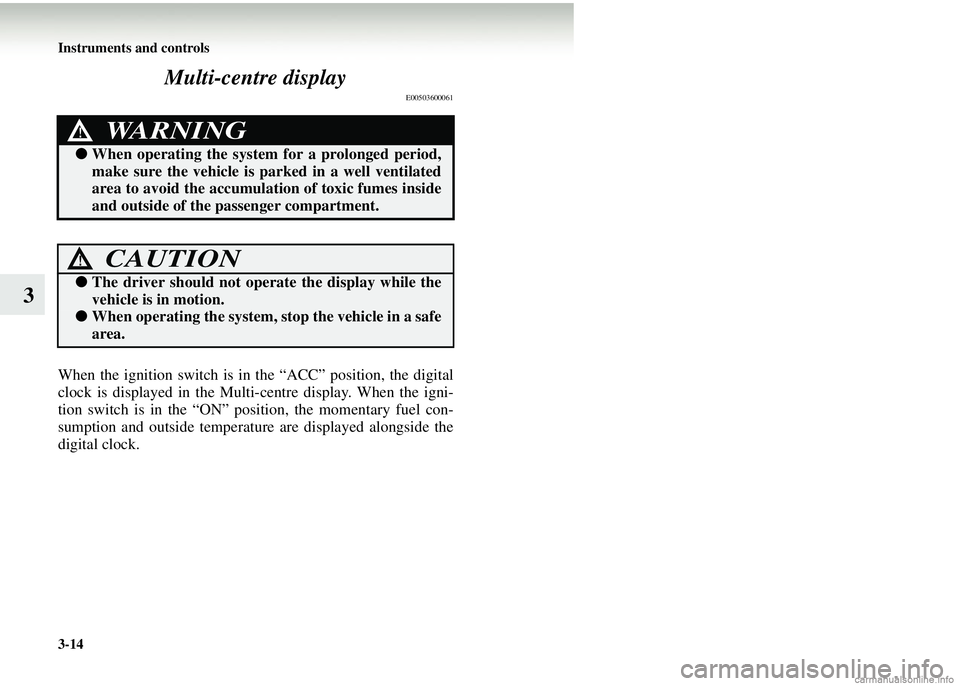
When the ignition switch is in the “ACC” position, the digital
clock is displayed in the Multi-
centre display. When the igni-
tion switch is in the “ON” position, the momentary fuel con-
sumption and outside temperature are displayed alongside the
digital clock.
WARNING!
● When operating th e system for a prolonged period,
make sure the vehicle is parked in a well ventilated
area to avoid the accumulation of toxic fumes inside
and outside of the passenger compartment.
CAUTION!
● The driver should not opera te the display while the
vehicle is in motion.
● When operating the system, stop the vehicle in a safe
area.
Page 135 of 450
Instruments and controls3-15
3
NOTE●The display unit (ex. km or mile) and brightness can be changed as desired. (Refer to “ Display brightness adjustment” on page
3-26 and “Display unit selection” on pa ge 3-28.) When the system cannot provide a definite value for momentary fuel con-
sumption/average fuel consumption/driving rang e/average speed, it is displayed as “---”.
● The figure on the display varies according to the conditions unde r which a vehicle is travelling (road conditions, the manner in
which the vehicle is being driven, etc.).
Observe the display for reference because the figure on the display may differ from the actual figure.
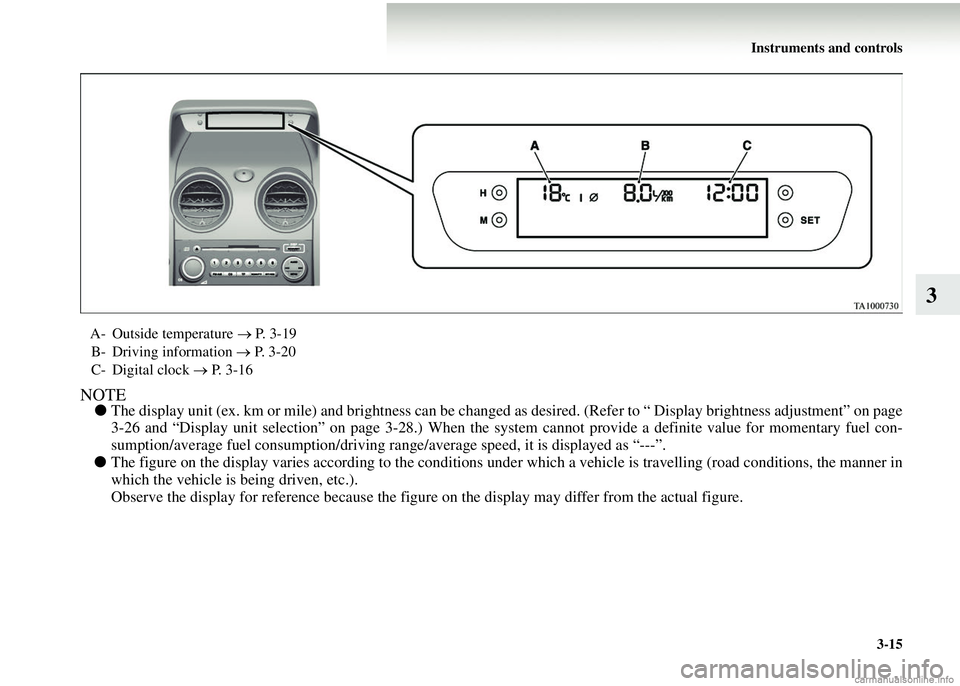
A- Outside temperature → P. 3-19
B- Driving information → P. 3-20
C- Digital clock → P. 3-16
Page 137 of 450
Instruments and controls3-17
3
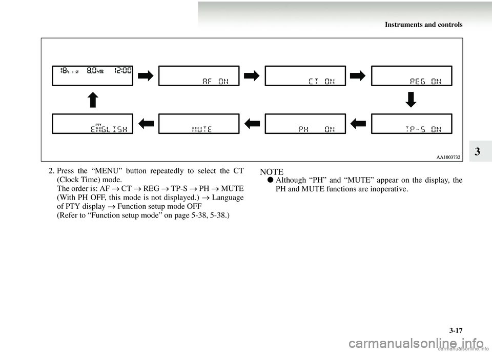
2. Press the “MENU” button repeatedly to select the CT(Clock Time) mode.
The order is: AF → CT → REG → TP-S → PH → MUTE
(With PH OFF, this mode is not displayed.) → Language
of PTY display → Function setup mode OFF
(Refer to “Function setup mode” on page 5-38, 5-38.)NOTE● Although “PH” and “MUTE” appear on the display, the
PH and MUTE functi ons are inoperative.
Page 138 of 450
3-18 Instruments and controls
3
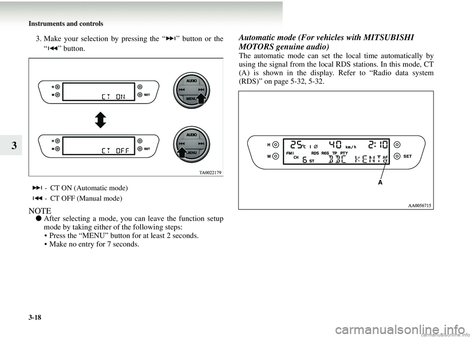
3. Make your selection by pressing the “ ” button or the“ ” button.
NOTE● After selecting a mode, you can leave the function setup
mode by taking either of the following steps: • Press the “MENU” button for at least 2 seconds.
• Make no entry for 7 seconds.
Automatic mode (For ve hicles with MITSUBISHI
MOTORS genuine audio)
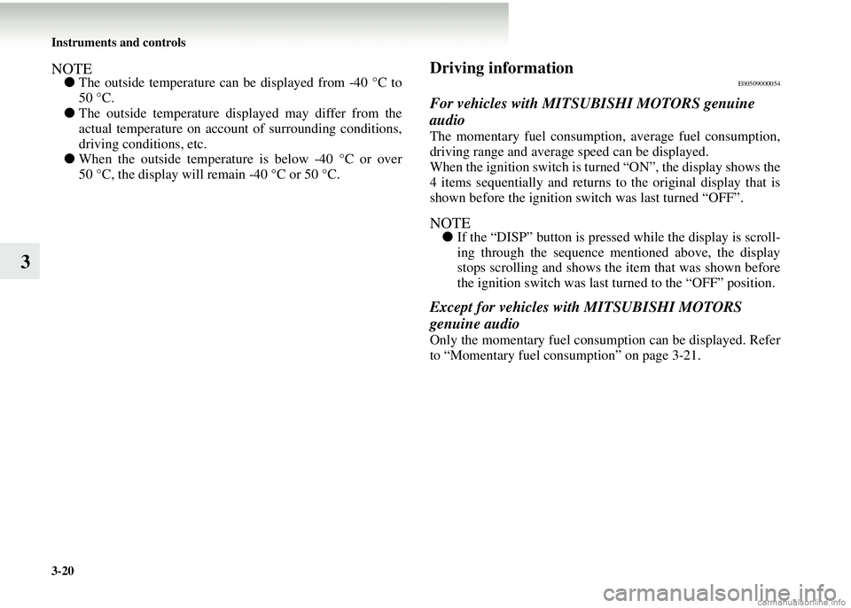
The automatic mode can set the local time automatically by
using the signal from the local RDS stations. In this mode, CT
(A) is shown in the display. Refer to “Radio data system
(RDS)” on page 5-32, 5-32.
- CT ON (Automatic mode)
- CT OFF (Manual mode)
Page 140 of 450
3-20 Instruments and controls
3
NOTE●The outside temperature can be displayed from -40 °C to
50 °C.
● The outside temperature displayed may differ from the
actual temperature on account of surrounding conditions,
driving conditions, etc.
● When the outside temperatur e is below -40 °C or over
50 °C, the display will remain -40 °C or 50 °C.Driving informationE00509000054
For vehicles with MITSUBISHI MOTORS genuine
audio
The momentary fuel consumption, average fuel consumption,
driving range and average speed can be displayed.
When the ignition switch is turn ed “ON”, the display shows the
4 items sequentially and returns to the original display that is
shown before the ignition switch was last turned “OFF”.
NOTE● If the “DISP” button is pressed while the display is scroll-
ing through the sequence mentioned above, the display
stops scrolling and shows the item that was shown before
the ignition switch was last turned to the “OFF” position.
Except for vehicles with MITSUBISHI MOTORS
genuine audio
Only the momentary fuel consumption can be displayed. Refer
to “Momentary fuel consumption” on page 3-21.